
Related Manuals for SCHUNK ECM


Summary of Contents for SCHUNK ECM
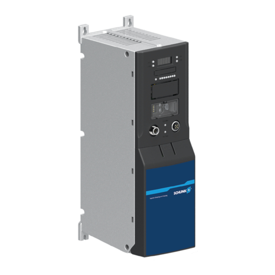
- Page 1 Original Operating Manual Assembly and Operating Manual Controller for SCHUNK gripper Firmware 2.x, 3.x...
- Page 2 Imprint Imprint Copyright: This manual is protected by copyright. The author is SCHUNK GmbH & Co. KG. All rights reserved. Technical changes: We reserve the right to make alterations for the purpose of technical improvement. Document number: 1378373 Version: 02.00 | 13/10/2022 | en...
-
Page 3: Table Of Contents
Digital input and output variants................ 19 Housing dimensions ................... 19 Design and description.................... 20 Design ......................... 20 Description ...................... 23 Interfaces...................... 23 4.3.1 CAN bus and PROFIBUS ................ 23 4.3.2 PROFINET.................... 24 02.00 | ECM | Assembly and Operating Manual | en | 1378373... - Page 4 6.2.2 Regulator operating behaviour with a connected module..... 56 6.2.3 Commissioning with PROFINET interface .......... 56 6.2.4 Projecting of the regulator .............. 57 Troubleshooting ..................... 65 EU-Declaration of Conformity ................. 66 Annex to Declaration of Conformity................ 67 02.00 | ECM | Assembly and Operating Manual | en | 1378373...
-
Page 5: General
The term "product" replaces the product name on the title page in this manual. 1.1.3 Applicable documents • General terms of business * • Catalog data sheet of the purchased product * 02.00 | ECM | Assembly and Operating Manual | en | 1378373... -
Page 6: Variants
• ECM with CAN bus • ECM with PROFIBUS • ECM with PROFINET • ECM with CAN bus or PROFIBUS or PROFINET and digital inputs and outputs 1.2 Warranty If the product is used as intended, the warranty is valid for 24... -
Page 7: Basic Safety Notes
• Make sure that the product is used only in the context of its } 3 [ / defined application parameters, 17]. 02.00 | ECM | Assembly and Operating Manual | en | 1378373... -
Page 8: Electromagnetic Compatibility
Test and measurement procedures - Testing the (2011) interference immunity to electromagnetic high frequency fields EN 61000-4-6 Test and measurement procedures - interference (2014) immunity to conducted interference variables induced by high frequency fields 02.00 | ECM | Assembly and Operating Manual | en | 1378373... - Page 9 1, measured with 10 m distance) has been tested according to the following standards: Standard Title EN 55011 Industrial, scientifical and medical devices - radio (2009) interference - limits and measurement procedures 02.00 | ECM | Assembly and Operating Manual | en | 1378373...
-
Page 10: Personnel Qualification
• Wear protective gloves and safety goggles when handling hazardous substances. • Wear close-fitting protective clothing and also wear long hair in a hairnet when dealing with moving components. 02.00 | ECM | Assembly and Operating Manual | en | 1378373... -
Page 11: Notes On Safe Operation
• Do not recommission the product until the malfunction has been rectified. • Test the product after a malfunction to establish whether it still functions properly and no increased risks have arisen. 02.00 | ECM | Assembly and Operating Manual | en | 1378373... -
Page 12: Disposal
Falling loads may cause serious injuries and even death. • Stand clear of suspended loads and do not step into their swiveling range. • Never move loads without supervision. • Do not leave suspended loads unattended. 02.00 | ECM | Assembly and Operating Manual | en | 1378373... -
Page 13: Protection During Commissioning And Operation
Before starting up the machine or automated system, check that the EMERGENCY STOP system is working. Prevent operation of the machine if this protective equipment does not function correctly. 02.00 | ECM | Assembly and Operating Manual | en | 1378373... -
Page 14: Protection Against Electric Shock
• The effectiveness of the potential equalisation must be verified by executing regular safety measurements. 02.00 | ECM | Assembly and Operating Manual | en | 1378373... -
Page 15: Protection Against Magnetic And Electromagnetic Fields
A special additional EMC test may be necessary if the system has a high risk potential. 02.00 | ECM | Assembly and Operating Manual | en | 1378373... -
Page 16: Notes On Particular Risks
For all work in the vicinity of hot surfaces, wear safety gloves. • Before carrying out any work, make sure that all surfaces have • cooled down to the ambient temperature. 02.00 | ECM | Assembly and Operating Manual | en | 1378373... -
Page 17: Technical Data
Max. power output Block commutation [VA] 324 ± 10 % Sine commutation [VA] 286 ± 10 % Max. output voltage Block commutation [V] 17 ± 10 % Sine commutation [V] 15 ± 10 % Max. output current [A] 02.00 | ECM | Assembly and Operating Manual | en | 1378373... - Page 18 PROFINET. It is not possible to combine the PROFIBUS, CAN bus and PROFINET. The USB interface is always available and additional digital inputs and outputs can be chosen as an option. 02.00 | ECM | Assembly and Operating Manual | en | 1378373...
-
Page 19: Digital Input And Output Variants
17.3 ±0.3 V Turn-off threshold at 20°C [V] 5.6 ±0.3 V Reverse polarity protection Overcurrent protection Surge protection up to max. [V] 3.4 Housing dimensions Housing dimensions (mm) 02.00 | ECM | Assembly and Operating Manual | en | 1378373... -
Page 20: Design And Description
Design and description 4 Design and description 4.1 Design Design with CAN bus or Profibus interface 02.00 | ECM | Assembly and Operating Manual | en | 1378373... - Page 21 Design and description Design with PROFINET interface 02.00 | ECM | Assembly and Operating Manual | en | 1378373...
- Page 22 Supply voltage terminal Logic voltage connection and motor voltage strip Fuse F2 Logic voltage fuse AVT terminal strip Connection for absolute-value transducer ENCODER terminal strip Encoder connection 02.00 | ECM | Assembly and Operating Manual | en | 1378373...
-
Page 23: Description
CAN bus and PROFIBUS interface M12 input connector LED "Bus State" M12 output connector LED "Operation" Color Function Operation Yellow Indicates whether there is communication. Bus State Green Displays the existing connection. 02.00 | ECM | Assembly and Operating Manual | en | 1378373... - Page 24 PROFINET interface RJ45 Ethernet connector "Activity" LED "Network Status" LED "Module Status" LED "Link" LED Color Function Link Green Displays the existing connection. Activity Yellow Displays the data traffic. 02.00 | ECM | Assembly and Operating Manual | en | 1378373...
- Page 25 • Flashes red twice and goes out if the IP address is unknown. • Flashes red three times and goes out if there are configuration errors. 02.00 | ECM | Assembly and Operating Manual | en | 1378373...
- Page 26 • Flashes red if there is a serious fault with the product. • Flashes red if the product is not ready for operation. • Flashes green/red alternately if a firmware update is being carried out. 02.00 | ECM | Assembly and Operating Manual | en | 1378373...
-
Page 27: Digital Inputs And Outputs
Lights up, when the input voltage is detected as On or Off. Switching threshold The following diagram shows the switching threshold in relation to the input voltage of a digital input. 02.00 | ECM | Assembly and Operating Manual | en | 1378373... - Page 28 Design and description Switching threshold diagram Input voltage Status of the input 02.00 | ECM | Assembly and Operating Manual | en | 1378373...
-
Page 29: Led Display
"RDY" is off) Software in Flashing Flashing undefined alternately with alternately with condition LED "ERR" LED "RDY" (on, when LED (on, when LED "ERR" is off) "RDY" is off) 02.00 | ECM | Assembly and Operating Manual | en | 1378373... -
Page 30: Dip Switch
SW2 DIP switch: –HOST enable Only when the logic voltage For SCHUNK is switched on after setting service the switch: personnel –Flash mode ARM For SCHUNK service personnel 02.00 | ECM | Assembly and Operating Manual | en | 1378373... - Page 31 Complete quick test - CMD ACK see "Schunk Motion Tool" software manual Relative travel see "Schunk Motion Tool" software manual CMD REFERENCE see "Schunk Motion Tool" software manual 02.00 | ECM | Assembly and Operating Manual | en | 1378373...
-
Page 32: Assembly And Settings
Sensor cable ✓ Brake cable if necessary ✓ Temperature sensor cable if necessary ✓ } 5.2.2.2 [ / 4. Secure external power cicuit, 34]. 5. Connect plug for fieldbus. 02.00 | ECM | Assembly and Operating Manual | en | 1378373... -
Page 33: Connections
Mount the product horizontally. • Protect the product from foreign objects. • Observe assembly distances. • Keep ventilation slits unobstructed. • Assembly distances in the control cabinet (mm) 02.00 | ECM | Assembly and Operating Manual | en | 1378373... -
Page 34: Electrical Connection
Module Connection diagram 5.2.2.2 External fusing The power circuit of the ECM must be protected by the customer. The trip value is to be determined from the relavent Assembly and Operating Manual of the ECM product connected. 02.00 | ECM | Assembly and Operating Manual | en | 1378373... - Page 35 Supply voltage terminal strip Connection assignment Terminal Function Logic voltage +24V Logic voltage and motor voltage GND Supply voltage +24 V Logic voltage and supply voltage GND Functional ground 02.00 | ECM | Assembly and Operating Manual | en | 1378373...
- Page 36 Functional ground Black Motor phase U Motor phase V White Motor phase W Motor cable shield connection is achieved via the cable clamp below the motor terminal strip. 02.00 | ECM | Assembly and Operating Manual | en | 1378373...
- Page 37 2.0 x 60 mm Stripped length: 8 mm Conductor cross-section: 0.14 to 0.5 mm Connection of the external component is shown in the circuit diagram. ENCODER terminal strip 02.00 | ECM | Assembly and Operating Manual | en | 1378373...
- Page 38 Conductor cross-section: 0.14 to 0.5 mm Connection of the external component is shown in the circuit diagram. HALL terminal strip Connection assignment Function +5 V HALL1 XHALL1 HALL2 XHALL2 HALL3 XHALL3 02.00 | ECM | Assembly and Operating Manual | en | 1378373...
- Page 39 XCLK Data XData +5V Enable (for activating the absolute-value transducer) Enable (bridges between Pin9 and Pin10 activate the absolute-value transducer) +5V (UB) supply voltage for the connected encoder) 02.00 | ECM | Assembly and Operating Manual | en | 1378373...
- Page 40 For functional shielding, connect the shield of the resolver on the cable clamp with shield connection over a large surface. 5.2.2.6 Brake If the module has a brake, it has to be connected to terminal strip 02.00 | ECM | Assembly and Operating Manual | en | 1378373...
- Page 41 0.4 x 2.0 x 60 mm Stripped length: 8 mm Conductor cross-section: 0.14 to 0.5 mm Connection of the external component is shown in the circuit diagram. 02.00 | ECM | Assembly and Operating Manual | en | 1378373...
- Page 42 1. Connect the fieldbus feed lines to fieldbus M12 input plug (1). 2. Fieldbus rerouting or fieldbus termination resistor , connect to fieldbus M12 output connector 02.00 | ECM | Assembly and Operating Manual | en | 1378373...
- Page 43 CAN Low Data line Thread Shield FE connection NOTE A termination resistor must be connected to the last bus device (120 Ω for CAN bus, 150 Ω for Profibus). 02.00 | ECM | Assembly and Operating Manual | en | 1378373...
- Page 44 Receive minus Receive plus Transmit minus Transmit plus 5.2.2.9 Digital input and output variants Digital inputs and outputs Signal Description +24 V Power supply Digital outputs Digital Inputs 02.00 | ECM | Assembly and Operating Manual | en | 1378373...
- Page 45 Assembly and settings 5.2.2.10 Wiring diagram ECM wiring diagram - Overview 02.00 | ECM | Assembly and Operating Manual | en | 1378373...
- Page 46 Assembly and settings ECM wiring diagram - with PROFINET and digital input/outputs 02.00 | ECM | Assembly and Operating Manual | en | 1378373...
- Page 47 Assembly and settings ECM wiring diagram with EGN / EZN 02.00 | ECM | Assembly and Operating Manual | en | 1378373...
- Page 48 Assembly and settings ECM wiring diagram 02.00 | ECM | Assembly and Operating Manual | en | 1378373...
-
Page 49: Setting The Baud Rate
The Baud rate that has been set can be read off on the ✓ seven-segment display. 5.4 Setting the fieldbus address Set the fieldbus address 1. Switch off the logic voltage. 02.00 | ECM | Assembly and Operating Manual | en | 1378373... - Page 50 When the regulator is operating, the fieldbus address that has been set can be read off on the seven-segment display. Fieldbus address range Fieldbus Decimal Hexadecimal address address range range PROFIBUS 0-125 CAN bus 0-255 02.00 | ECM | Assembly and Operating Manual | en | 1378373...
-
Page 51: Updating Firmware
2. When logic voltage supply is provided, turn switch 3 to "ON" on the SW1 DIP switch (HOST enable). The seven-segment display briefly indicates "GET" and then ✓ "HOS". The EEPROM record is automatically saved on the USB stick. 02.00 | ECM | Assembly and Operating Manual | en | 1378373... -
Page 52: Establishing The Factory Settings
2. On the SW1 DIP switch, turn switch 1 to "ON". 3. Switch on the logic voltage. 4. On the SW1 DIP switch, turn switch 1 to "OFF". 02.00 | ECM | Assembly and Operating Manual | en | 1378373... -
Page 53: Resetting The Profinet Interface
2. Remove the connection plug, both ports must be idle. The PROFINET interface is reset. ✓ 3. Insert the connection plug 4. On the SW1 DIP switch, turn switch 1 to "OFF". 02.00 | ECM | Assembly and Operating Manual | en | 1378373... -
Page 54: Start-Up
HEX format on the seven-segment display. An error message is pending and the regulator is not ready for operation. 8. If an error message is pending, eliminate the error } 7 [ / 65]. 02.00 | ECM | Assembly and Operating Manual | en | 1378373... -
Page 55: Profinet
– Smallest supported network cycle time 0.25ms = 250μs – Synchronization of the application not possible The product is incorporated into the PROFINET network as an IO device. 02.00 | ECM | Assembly and Operating Manual | en | 1378373... -
Page 56: Regulator Operating Behaviour With A Connected Module
An error message is pending and the regulator is not ready for operation. } 7 [ / 9. If an error message is pending, eliminate the error: 65]. 02.00 | ECM | Assembly and Operating Manual | en | 1378373... -
Page 57: Projecting Of The Regulator
The project engineering software Siemens TIA-Portal is started. ■ 1. Choose option Extras > Manage device description file (GSD). The Manage device description file window will be ✓ displayed. 02.00 | ECM | Assembly and Operating Manual | en | 1378373... - Page 58 3. Highlight the current GSDML file of the product by checking the box. 4. Start the import of the highlighted GSDML file with Install. The Installation window displays the installation steps. ✓ 02.00 | ECM | Assembly and Operating Manual | en | 1378373...
- Page 59 Start-up 5. Confirm the successful completion of the installation with Close. The product will then be automatically made available in the catalog of available hardware: 02.00 | ECM | Assembly and Operating Manual | en | 1378373...
- Page 60 2. Highlight the product and select the Device View tab. 3. Specify the addresses of the inputs and outputs with the Input/ Output Frame option or the Input/Output Element option. 02.00 | ECM | Assembly and Operating Manual | en | 1378373...
- Page 61 4. If necessary, adjust the product name in the Properties – General tab. 5. If necessary, adjust the IP addresses in the Properties – PROFINET interface [X1] – Ethernet Addresses tab. 02.00 | ECM | Assembly and Operating Manual | en | 1378373...
- Page 62 8. Press the Translate button to check the accuracy of the projecting. If an error or a warning is displayed, remove it and press the Translate button again. The Translate button is displayed. ✓ 02.00 | ECM | Assembly and Operating Manual | en | 1378373...
- Page 63 After a successful check, the Translate window will close ✓ automatically. 9. Highlight the CPU of the higher-level control in the project and press the Load in Device button. The Enhanced Load window is shown. ✓ 02.00 | ECM | Assembly and Operating Manual | en | 1378373...
- Page 64 CPU of the higher-level control is displayed. 12. Select the CPU of the higher-level control and press the Load button. The data will be transferred. ✔ 02.00 | ECM | Assembly and Operating Manual | en | 1378373...
-
Page 65: Troubleshooting
Identified errors are shown as hexadecimal code on the seven- segment display. For information on the error codes, see the Schunk Drive Protocol (SDP) or Schunk Motion Protocol (SMP) software manuals. 02.00 | ECM | Assembly and Operating Manual | en | 1378373... -
Page 66: Eu-Declaration Of Conformity
- Emission standard for industrial environments (IEC 61000-6-4:2006 + A1:2010); Signed for and on behalf of: SCHUNK GmbH & Co. KG Dr.-Ing. Manuel Baumeister, Technology & Innovation Lauffen/Neckar, October 2022 02.00 | ECM | Assembly and Operating Manual | en | 1378373... -
Page 67: Annex To Declaration Of Conformity
0315058 ECM-EZN064-CN-I 1325331 ECM-EZN064-PB-N 0315059 ECM-EZN100-CN-I 1325334 ECM-EZN100-PB-N 0315083 ECM-EGN080-PN-N 1325341 ECM-EGN080-CN-N 0315084 ECM-EGN100-PN-N 1325342 ECM-EGN100-CN-N 0315085 ECM-EGN160-PN-N 1325344 ECM-EGN160-CN-N 0315086 ECM-EZN064-PN-N 1325347 ECM-EZN064-CN-N 0315087 ECM-EZN100-PN-N 1325349 ECM-EZN100-CN-N 02.00 | ECM | Assembly and Operating Manual | en | 1378373... - Page 68 Original Operating Manual SCHUNK GmbH & Co. KG Clamping and gripping technology Bahnhofstr. 106 - 134 D-74348 Lauffen/Neckar Tel. +49-7133-103-0 Fax +49-7133-103-2399 info@de.schunk.com schunk.com Folgen Sie uns I Follow us...
Need help?
Do you have a question about the ECM and is the answer not in the manual?
Questions and answers