
Related Manuals for Regulus VZK S 3 230-2P Series


Summary of Contents for Regulus VZK S 3 230-2P Series
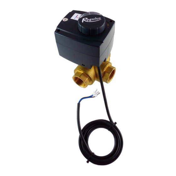
- Page 1 Installation and Operation Manual THREE-WAY ZONE BALL VALVE VZK S 3xx-230-2P VZK S 3xx-230-2P...
-
Page 2: Table Of Contents
3.3. Actuator Placing ....................6 4. L-bore Valves ......................... 7 4.1. Valve Adjustment Options ................7 5. T-bore Valves ......................... 8 5.1. Valve Adjustment Options ................8 6. Permissible and Prohibited Positions ................10 THREE-WAY ZONE BALL VALVE - www.regulus.eu │... -
Page 3: Introduction
3 x G 1" F 14.3 T-bore Valves Marking VZK S 325-230-2P-60 T 3/4F 18674 3 x G 3/4" F 20.0 13.1 VZK S 325-230-2P-60 T 1F 18675 3 x G 1" F 28.3 14.3 THREE-WAY ZONE BALL VALVE - www.regulus.eu │... - Page 4 Protection class Power cable cross section 3 x 0.5 mm Power cable length Materials Valve housing brass CW617N Valve spindle brass CW617N Valve ball chrome-plated brass O-rings EPDM, FPM Seal PTFE Power cable THREE-WAY ZONE BALL VALVE - www.regulus.eu │...
-
Page 5: Actuator
The actuator is equipped with end stops so the controller can be permanently switched through one of the outputs into the actuator. However, the controller must never close both the outputs for valve control simultaneously, otherwise the actuator will get damaged. Wiring diagram THREE-WAY ZONE BALL VALVE - www.regulus.eu │... -
Page 6: Actuator Control
If required, the actuator can be removed and fitted in a different position (in quarter turns) - see the fig. The label shall be then carefully removed and rotated to the correct position according to the ports arrangement. Default position of the valve actuator THREE-WAY ZONE BALL VALVE - www.regulus.eu │... -
Page 7: L-Bore Valves
Default position Default position Label on the actuator Blue indicator Red indicator Warning: Other settings than the default factory adjustment are not possible. THREE-WAY ZONE BALL VALVE - www.regulus.eu │... -
Page 8: T-Bore Valves
A label showing the fluid flow direction in colour corresponding to the colour shown by the knob position is placed on the actuator. Default position Position after turning Label on the actuator Blue indicator Red indicator THREE-WAY ZONE BALL VALVE - www.regulus.eu │... - Page 9 Switch the actuator to automatic mode. Remove the label from the actuator and replace it with the enclosed label showing the corresponding setting. Default position Position after turning Label on the actuator Red indicator Blue indicator THREE-WAY ZONE BALL VALVE - www.regulus.eu │...
-
Page 10: Permissible And Prohibited Positions
6. Permissible and Prohibited Positions WARNING - Important Installation of the valve in a position where the actuator is located below the valve is prohibited. - Page 12 ©2021 We reserve the right to errors, changes and improvements without prior notice. REGULUS spol. s r.o. E-mail: sales@regulus.eu Web: www.regulus.eu...
Need help?
Do you have a question about the VZK S 3 230-2P Series and is the answer not in the manual?
Questions and answers