Advertisement
Quick Links
EN
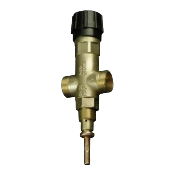
JBV1 - Thermostatic Recooling One-way Valve
Use
This thermostatic recooling one-way valve is designed to protect central-heating heat sources
against overheating. The valve in its brass body is controlled by a thermostatic element. When
the limit temperature of heating water is reached, the valve opens and lets the cold water from
the mains flow in and cool down the heating water in a heat exchanger. Heated cooling water is
discharged into the sewer system. As soon as the water temperature drops below the limit, the
valve closes.
If the pressure in the mains could be above 6 bar, it is necessary to install a pressure reducer at
the inlet of cooling water.
Warning: This valve is NO substitution for a safety valve!
Technical Data
Type:
JBV1
Opening temperature (limit):
97 °C (±2 °C)
Max. temperature:
120 °C
Max. pressure on the boiler side:
4 bar
Max. pressure on the water side:
6 bar
Nominal flow rate at ∆ p 1 bar:
1.8 m
3
/hour at 110 °C water temperature
Valve to heat source coupling:
G ½" outer
Cooling water coupling:
G ¾" outer
Installation
Installation may be done by qualified personnel only.
On order to ensure flawless operation of this thermostatic recooling one-way valve (JBV1), it is
necessary to respect the installation conditions set by the manufacturer of your heating source and
the flow directions marked on its body. JBV1 shall be always mounted to a place where the highest
temperature in case of overheating is reached (usually in the upper part of the heat source or in the
outgoing pipe close to the heat source). When installing JBV1, it is important to check whether the
G ½" sleeve will ensure total immersion of the valve's thermostatic element.
In order to ensure cooling down the boiler when needed, the cold water inlet shall be connected to
pos. „A" (Fig. 1), as shown in Fig. 3. or 4. A strainer shall be mounted into the cold water pipe to
remove mechanical impurities.
If a non-return valve is installed in the inlet piping, the thermostatic valve shall be connected as in
Fig. 4. Min. diameter of the connecting pipes is DN 16.
Always respect instructions from the manufacturer of your heat source, incl. the precise
position of the valve and a max. output and type of your heat source.
JBV1 WORKING POSITIONS
The JBV1 thermostatic recooling one-way valve can be mounted vertically as well as horizontally.
The valve must not be installed with its head down!
Regular maintenance
Once a year: turn the head of the thermostatic recooling one-way valve in order to remove possible
impurities. Clean the strainer at the cold water inlet.
cold
into
water
sewer
BOILER
in
Fig. 3: Piping diagram for JBV1 without a non-return valve used
BOILER
into
sewer
Fig. 4: Piping diagram for JBV1 with a non-return valve used
56
A
B
COOLING
COOLING
WATER
WATER
IN
OUT
G ½"
Fig. 1: Dimensions
Fig. 2: Piping diagram
KEY:
for JBV1
FORBIDDEN POSITION
ball valve
to
pressure reducer
a heating
system
strainer
safety valve
from
pump
a heating
system
KEY:
cold
ball valve
water in
pressure reducer
to
a heating
strainer
system
non-return
valve
safety valve
from
a heating
pump
system
REGULUS - TECHNIK, s.r.o.
Strojnícka 7G/14147
http://www.regulus.sk
080 01 Prešov
E-mail: obchod@regulus.sk
SK
Dochladzovací jednocestný termostatický ventil JBV1
Použitie
Dochladzovací jednocestný termostatický ventil je určený k ochrane tepelného zdroja ústredného
vykurovania proti prehriatiu. Ventil v mosadznom tele je ovládaný termostatickým členom. Pri
dosiahnutí limitnej teploty vykurovacej vody ventil otvára prívod tlakovej vody z vodovodného radu,
ktorá vo výmenníku chladí vykurovaciu vodu. Ohriata chladiaca voda je vypúšťaná do kanalizácie.
Pri poklese teploty vykurovacej vody pod limitnú, sa ventil samočinne uzatvorí.
Ak môže byť tlak vo vodovodnom rade vyšší ako 6 bar, je nutné zaradiť na vstup chladiacej vody
redukčný ventil.
Výstraha: Dochladzovací jednocestný termostatický ventil nenahrádza poistný ventil.
Technická charakteristika
Typ
JBV1
Otváracia teplota (limitná)
97 °C (± 2 °C)
Maximálna teplota
120 °C
Maximálny tlak na strane kotla
4 bar
Maximálny tlak na strane vody
6 bar
Nominálny prietok pri ∆ p 1 bar
1,8 m
3
/hod pri teplote vykurovacej vody 110 °C
Závit pre pripojenie ventilu na tepelný zdroj
G ½" vonkajší
Závit pre pripojenie potrubia chladiacej vody
G ¾" vonkajší
Inštalácia
Inštaláciu smie vykonávať iba odborne spôsobilá osoba.
Pre správnu funkciu dochladzovacieho jednocestného termostatického ventilu (ďalej len JBV1)
je nutné dodržať predpísané podmienky výrobcu tepelného zdroja pre jeho inštaláciu a dodržať
označenie smerov prietoku vyznačených na tele ventilu. JBV1 sa vždy inštaluje do miesta, kde pri
prehriati tepelného zdroja je teplota najvyššia (obvykle priamo v hornej časti zdroja alebo na výstup-
nom potrubí v tesnej blízkosti zdroja). Pri inštalácii ventilu JBV1 je nutné skontrolovať, či použitý
nátrubok G ½" zaistí po inštalácii JBV1 úplné ponorenie termostatického člena ventilu.
V mieste „A" (Obr. 1) sa pripojí podľa Obr. 3 alebo 4 prívod chladiacej vody, ktorá po uvedení ventilu
do prevádzky zaistí ochladenie kotla. Na prívode chladiacej vody musí byť namontovaný filter pre
zachytenie mechanických nečistôt.
Ak je v prívodnom potrubí namontovaná spätná klapka, je nutné pripojiť ventil podľa Obr. 4.
Minimálny priemer prípojného potrubia je DN 16.
Pri inštalácii vždy dodržujte pokyny výrobcu tepelného zdroja, ktorý špecifikuje presné
umiestnenie ventilu, maximálny výkon a typ zdroja.
PRACOVNÉ POLOHY „JBV1"
Dochladzovací jednocestný termostatický ventil JBV1 je možné montovať do zvislej aj do vodorovnej
polohy.
Dochladzovací jednocestný termostatický ventil sa nesmie namontovať hlavou ventila dole!
Pravidelná údržba
Kontrola 1× za 1 rok: Otočiť hlavou dochladzovacieho jednocestného termostatického ventilu, aby
sa odstránili prípadné nečistoty a usadeniny. Vyčistiť filter na vstupe chladiacej vody.
VSTUP
STUDENEJ
VODY
KOTOL
Obr. 3: Schéma inštalácie ventila JBV1 do vykurovacieho systému bez použitia spätnej klapky
KOTOL
Obr. 4: Schéma inštalácie ventila JBV1 do vykurovacieho systému s použitím spätnej klapky
56
A
B
VSTUP
VÝSTUP
CHLAD.
CHLAD.
VODY
VODY
G 1/2"
Obr. 1: Rozmerová schéma
Obr. 2: Pracovné polohy
dochladzovacieho ventilu
NEPRÍPUSTNÉ
armatúra uzatváracia
redukčný ventil
DO
VYKUR.
SYSTÉMU
filter
poistný ventil
Z VYKUR.
SYSTÉMU
VSTUP
armatúra uzatváracia
STUDENEJ
VODY
redukčný ventil
DO VYKUR.
filter
SYSTÉMU
spätná klapka
poistný ventil
Z VYKUR.
SYSTÉMU
REGULUS - TECHNIK, s.r.o.
Strojnícka 7G/14147
http://www.regulus.sk
080 01 Prešov
E-mail: obchod@regulus.sk
03/2013
Advertisement

Related Manuals for Regulus JBV1


Summary of Contents for Regulus JBV1
- Page 1 JBV1 sa vždy inštaluje do miesta, kde pri the flow directions marked on its body. JBV1 shall be always mounted to a place where the highest prehriati tepelného zdroja je teplota najvyššia (obvykle priamo v hornej časti zdroja alebo na výstup- Obr.
- Page 2 La valvola JBV 1 viene installata sempre nel punto, dove viene rilevata la w górnej części źródła lub na rurach wylotowych w pobliżu źródła). Podczas instalacji zaworu JBV1 massima temperatura - nel caso di surriscaldamento (di solito direttamente nella parte superiore della należy sprawdzić, czy króciec G ½”...
Need help?
Do you have a question about the JBV1 and is the answer not in the manual?
Questions and answers