Table of Contents
Advertisement
Quick Links
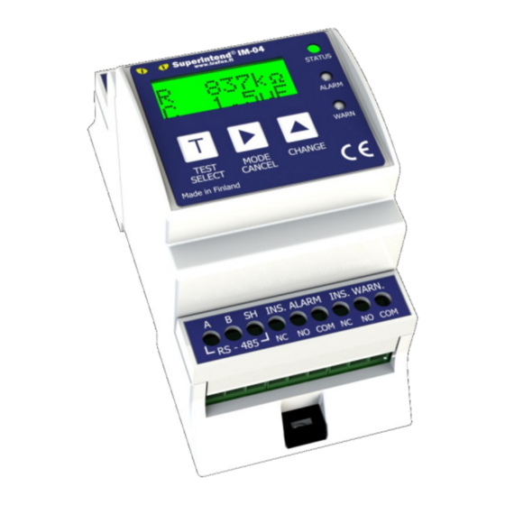
SUPERINTEND IM-04DCCT
IMD Insulation Monitoring device for non-grounded (IT) electrical
networks for DC charging station applications
Instructions for installation and use v10.60
AC/DC
Superintend IM-04DCCT Manual v10.60 English
Rights to modify the content reserved
© Copyright Muuntosähkö Oy - Trafox 3.2.2022
Advertisement
Table of Contents

Summary of Contents for Trafox SUPERINTEND IM-04DCCT
- Page 1 SUPERINTEND IM-04DCCT IMD Insulation Monitoring device for non-grounded (IT) electrical networks for DC charging station applications Instructions for installation and use v10.60 AC/DC Superintend IM-04DCCT Manual v10.60 English Rights to modify the content reserved © Copyright Muuntosähkö Oy - Trafox 3.2.2022...
-
Page 2: Table Of Contents
ALARM MENU ....................12 SETUP MENU ....................14 ERRORS ...................... 16 MODBUS RTU REMOTE CONTROL ..............16 TECHNICAL SPECIFICATIONS ................19 IM-04DCCT UNIT ..................... 19 HVC-10 UNIT....................19 MECHANICAL DIMENSIONS ................20 © Copyright Muuntosähkö Oy – Trafox Superintend IMD http://www.trafox.fi... -
Page 3: Instructions
Such sections are marked with the symbol shown below. A symbol indicating possible danger. A description of the symbol may be placed on the device or provided in the instructions for use. Superintend IMD © Copyright Muuntosähkö Oy - Trafox http://www.trafox.fi... -
Page 4: System Description
The IM-04DCCT unit comes with the connections shown in the following table. The shaded parts are optional and are installed as needed, while installing the other parts is mandatory. © Copyright Muuntosähkö Oy – Trafox Superintend IMD http://www.trafox.fi... - Page 5 Connector Description Connection 1 to IM-04DCCT Connection 2 to IM-04DCCT Connection 1 of the network to be monitored; Max 690VAC/1000VDC Connection 2 of the network to be monitored; Max 690VAC/1000VDC Superintend IMD © Copyright Muuntosähkö Oy - Trafox http://www.trafox.fi...
- Page 6 Figure 1. System connection. © Copyright Muuntosähkö Oy – Trafox Superintend IMD http://www.trafox.fi...
-
Page 7: Rs-485 Network Connection
When needed, set the Modbus address (SETUP→MB Addr). • If needed, enable the automatic alarm acknowledgement (SETUP→AutoRst). A more detailed description of the configuration is provided in the Manual section “SETUP menu”. Superintend IMD © Copyright Muuntosähkö Oy - Trafox http://www.trafox.fi... -
Page 8: Use
PE conductor. These generate a low current that travels through the insulation resistance and capacitance to be measured. The insulation resistance and capacitance are calculated by FFT analysing the current and then measuring the amplitude and phase. © Copyright Muuntosähkö Oy – Trafox Superintend IMD http://www.trafox.fi... -
Page 9: Menu Structure
• The Monitor menu mainly has one level. All information to be displayed can be viewed by browsing the menu with the button. Superintend IMD © Copyright Muuntosähkö Oy - Trafox http://www.trafox.fi... - Page 10 On the edit level, approves the changes made. Pressing the button in the first three items of the Monitor menu and approving the start of the test begins the system test. © Copyright Muuntosähkö Oy – Trafox Superintend IMD http://www.trafox.fi...
-
Page 11: Monitor Menu
Test OK; otherwise the text shown in Test FAILED, and an insulation fault alarm is given to indicate that the insulation resistance can no longer be measured. The Monitor menu functions as follows: Superintend IMD © Copyright Muuntosähkö Oy - Trafox http://www.trafox.fi... -
Page 12: Alarm Menu
All fixed faults can also be acknowledged on one go by means of the Alarm reset function in the Monitor menu. If the automatic alarm acknowledgement has been enabled (SETUP→AutoRst), the faults are acknowledged automatically as soon as they are fixed. © Copyright Muuntosähkö Oy – Trafox Superintend IMD http://www.trafox.fi... - Page 13 / fault limit of the fault first, followed by the fault start time. The insulation fault alarm is active. The smallest insulation resistance measured during the fault is 850 kΩ and the alarm limit is 900 kΩ. Superintend IMD © Copyright Muuntosähkö Oy - Trafox http://www.trafox.fi...
-
Page 14: Setup Menu
The password is “123”. All information on the settings of the device alarm limits and the system are saved in the internal EEPROM memory of the IM-04DCCT unit. © Copyright Muuntosähkö Oy – Trafox Superintend IMD http://www.trafox.fi... - Page 15 AUTOMATIC ALARM ACKNOWLEDGEMENT: This setting determines whether all the alarms shall be acknowledged automatically as soon as they are deactivated. • Filter: Not in use. • TIME: The time and date of the real time clock. Superintend IMD © Copyright Muuntosähkö Oy - Trafox http://www.trafox.fi...
-
Page 16: Errors
RS-485 bus. The unit's Modbus RTU slave functionality is now ready for use. The unit’s Modbus RTU register map is provided below. The Modbus functions to be used are Read Holding Registers (0x03) and Write Multiple Registers (0x10). © Copyright Muuntosähkö Oy – Trafox Superintend IMD http://www.trafox.fi... - Page 17 The resolution (jog) of the limit uint16 kOhm 50 if insulation resistance alarm limit 100 kOhm or parameter of the insulation above resistance pre-alarm 10 if insulation resistance alarm limit below 100 kOhm Superintend IMD © Copyright Muuntosähkö Oy - Trafox http://www.trafox.fi...
- Page 18 0x0010 = fault in the TG or MG wire deactivated the statuses will activate when the corresponding active alarm has been deactivated and remain active until the cause has been acknowledged © Copyright Muuntosähkö Oy – Trafox Superintend IMD http://www.trafox.fi...
-
Page 19: Technical Specifications
Other standards: IEC61557-8, IEC61010-1:2010-3, IEC 61851-23 HVC-10 UNIT Voltage ranges • Maximum voltage at the measurement connectors L1 and L2 [U ]: 1000VDC or 690VAC • Maximum leakage capacitance: 5 uF Superintend IMD © Copyright Muuntosähkö Oy - Trafox http://www.trafox.fi... -
Page 20: Mechanical Dimensions
IP class (front panel): IP40 • IP class (other casing): IP20 • Connector tightening torque: 0.5…0.6 Nm • Weight: 94 g MECHANICAL DIMENSIONS 62 mm 53,5 mm 110 mm 18 mm 62 mm 90,3 mm © Copyright Muuntosähkö Oy – Trafox Superintend IMD http://www.trafox.fi...


Need help?
Do you have a question about the SUPERINTEND IM-04DCCT and is the answer not in the manual?
Questions and answers