Linear AM-SEK User Manual
Serial-ethernet server
Hide thumbs
Also See for AM-SEK:
- Quick start manual (2 pages) ,
- Quick start manual (2 pages) ,
- Quick start manual (2 pages)
Table of Contents
Advertisement
Quick Links
Advertisement
Table of Contents

Related Manuals for Linear AM-SEK


Summary of Contents for Linear AM-SEK
- Page 1 AM-SEK Serial-Ethernet Server User Manual...
- Page 2 Published by Nortek Security & Control LLC. Toll-Free: (800) 421-1587. Website: www.nortekcontrol.com Copyright © 2021 Nortek Security & Control LLC. Linear and GTO are trademarks of Nortek Security & Control LLC. All rights reserved. All other product names referenced herein are registered trademarks of their respective companies.
-
Page 3: Table Of Contents
3.3.4 Configure AM-SEK as TCP Server........ - Page 4 4.2.1 Enable Virtual COM on AM-SEK ........
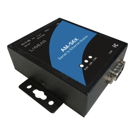
- Page 5 Figure 2.1 AM-SEK interfaces ........
-
Page 6: Introduction
TCP Server Mode The AM-SEK can be configured as a TCP server on TCP/IP Networks to wait for other applications (clients) in the host computer to establish a connection with the serial device. After the connection is established between serial device and... -
Page 7: Tcp Client Mode
UDP Mode UDP is a faster, but it’s a non-guaranteed datagram delivery protocol. AM-SEK can be configured in UDP mode on a TCP/IP Network to establish a connection using unicast or multicast data from the serial device to one or multiple host computers. -
Page 8: Tunneling Mode
Tunneling Mode The serial connection can be established with two or more AM-SEK devices to send data over TCP/IP Network. This helps nullify the 15-meter distance limitation normally imposed on an RS-232 interface. -
Page 9: Hardware Setup
2. Hardware Setup NOTE: 1. Panel layout available in Appendix A.3.1 2. Press the reset button of AM-SEK to reset the settings to the default values (see Figure 2.1 below). DC Jack 5VDC Reset Button DC 9~30V RJ45 10/100 Mpbs... -
Page 10: Installation Procedures
It can also be connected to the PC‘s Ethernet port via a cross- over Ethernet cable for easy set up. However in this case, it’s necessary to make sure the PC is in the same network sub-net as the AM-SEK. -
Page 11: Auto Ip (Dynamic Ip)
A DHCP server can automatically assign the IP address and network settings. AM-SEK supports the DHCP function. By default, the DHCP function on AM-SEK is disabled, so the Monitor.exe software can be used to search network information automatically using the following steps: 1. -
Page 12: Configuration By Telnet Utility
2. Telnet to AM-SEK using command Telnet IP address. (For example: Input Telnet 10.0.50.100 in Ms-DOS command prompt window). Once connected to the AM-SEK, the system prompts for a password. The default password is the word default (see Figure 3.4 below). -
Page 13: Networking
This page allows a change of the network settings of the device including IP address, Subnet Mask, Gateway IP Address and SNMP Information of the AM-SEK. Please notice that any setting change made on this page won’t take effect until one restart the device. -
Page 14: Change The Password
3.2.3 Change the Password 1. Select 3 from Input choice and enter (0~4). The following screen appears: Figure 3.8 Change the password To change the password, please type the old password in the Please input old password field. Type the new password in the Please input new password and the Please verify new password fields. -
Page 15: Figure 3.10 Link Mode-Tcp Server Setup
• IP filtering function is disabled if FILTER_IP is set to “0.0.0.0”. • By default, IP filter is disabled. • If IP filter is enabled, only the source IP assigned can connect to AM-SEK. Figure 3.10 Link Mode-TCP server setup... -
Page 16: Configure Am-Sek As Tcp Client
3.2.5 Configure AM-SEK as TCP Client 1. Type 2 in the Input choice (1~5) and enter (see Figure 3.11 below). 2. Input the destination IP in the Please input Destination IP option. 3. Input the destination port in the Please input Destination port option. -
Page 17: Configure Am-Sek As Udp Client
3.2.6 Configure AM-SEK as UDP Client For example, the local port is 4660, the destination IP is 10.0.29.254 and the destination port is 1234). Figure 3.12 Link Mode-UDP client setup 3.2.7 COM Port Setting Enter 2 for Input choice and enter (1~4) for COM1. The following screen appears. The COM port alias name can be given, the baud rate and parity can be set, the number of data bit and stop bit can be determined, the use of flow control and the type of flow control to be used can be decided. -
Page 18: Enabling Serial Data Buffer
Type 3 from Input choice and enter (1~4) for COM1. By default, COM port serial data buffer is enabled. This means that when TCP/IP Ethernet connection is broken, serial data collected from serial device will be empty in AM-SEK once TCP/ IP connection is resumed. -
Page 19: Accept Control Command From Com Port
1. Confirm that the PC is located on the same network sub-net as AM-SEK 2. Open a web browser, then type in the IP address of AM-SEK to be configured. Default user name is admin and default password is default (password is blank for firmware versions 3.605 or earlier). -
Page 20: Change The Password
3. The following overview page is displayed. Figure 3.18 Overview 3.3.2 Change the password 1. Click the Security link, and the following screen is displayed. Figure 3.19 Change the password • Input the current password in the Old Password field, input the new password in the New Password and Verified Password fields, and then click Save Configuration to update the password. -
Page 21: Network Setup
3. Enable SNMP by checking Enable. Fill in network identification information under the SNMP field. 4. Click the Save Configuration button to save the changes. Note that the setting will not become effective until the AM-SEK is restarted. Figure 3.20 Network setup... -
Page 22: Configure Am-Sek As Tcp Server
Note: • Default port number of AM-SEK is 4660 and it is associated with serial port COM1 respectively. After the application program connects to the TCP port 4660 of AM-SEK, data being sent to this TCP connection from the application program are transparent to the COM1 of AM-SEK. -
Page 23: Configure Am-Sek As Tcp Client
3.3.5 Configure AM-SEK as TCP Client Configure AM-SEK as TCP client. For example, the destination IP is 10.0.29.11, and the destination port is 4660. 1. Input destination IP 10.0.29.11. 2. Input destination port in the 4660. 3. Input an idle time in the Idle time to send TCP alive packet option. (If the input is 4, the sending TCP keep alive packet period will be change to 4*10 sec) •... -
Page 24: Assign A New Ip Address By Arp Command
3.4 Assign a New IP Address by ARP Command Use ARP command to assign a static IP address of the AM-SEK using its hardware MAC address. The MAC address is printed on the rear side of device in this format: "0060E9-xxxxxx". The following example displays how to set this up using MS-DOS command prompt window. -
Page 25: Using Virtual Com
4. Using Virtual COM Virtual COM driver mode for windows converts COM data to LAN data to control the RS-232 port on a AM-SEK via the LAN. By creating virtual COM ports on the PC, the Virtual COM driver redirects the communications from the virtual COM ports to an IP address and port number on a AM-SEK that connects the serial line device to the network. -
Page 26: Setup Of A Virtual Com Driver
4.2.1 Enable Virtual COM on AM-SEK From the web browser, access the AM-SEK (by typing its IP address) then click COM1 link to access COM1 page. On the top half of the page, click TCP Server and selct the Enable button to enable Virtual COM. Next, type in the local port number in the Local Port field (see below): Figure 4.2 Enable Virtual Com... -
Page 27: Run Serial/Ip On Monitoring Pc
Virtual COM can also be enabled through telnet configuration by setting COM1 as a TCP server. Type in the local port number for COM1, then enable virtual COM as shown in the figure below. Figure 4.3 Enable Virtual Com via telnet 4.2.2 Run Serial/IP on Monitoring PC In the Window Start Menu, select Programs, select Serial/IP then select Control Panel. -
Page 28: Configuring Virtual Com Ports
4.3 Configuring Virtual COM Ports Please configure each Serial/IP COM port as follows: 1. Select a COM port on the list. 2. For IP Address of Server, enter a numeric IP address for the serial server. 3. For Port Number, enter the TCP port number that the serial server uses to provide its serial ports to the network. 4. -
Page 29: Snmp Setup
IP address, DNS name, system descriptions and NIC information, etc. 6. Start Writing One’s Own Applications Before writing one’s host applications or programs to interact with the AM-SEK, please make sure to have done the following: 6.1 Preparing the System... -
Page 30: Tcptest2 In Visual C
Always use '=' then Enter key to exit the program. 7. Diagnostics There are several ways to can check on the status and availability of the AM-SEK. 7.1 Use Standard TCP/IP Utility Ping Command From Windows Start menu, select Run and type in ping <TCP Server IP address>... -
Page 31: Use Monitor.exe Configuration Utility Program
7.2 Use Monitor.exe Configuration Utility Program Use the monitor.exe configuration (available at www.linear-solutions.com) to check on the status of AM-SEK. The status can be read from AP version column of the tool. Status Descriptions The system is configured as a TCP Server and Listing. -
Page 32: Appendix A: Specifications
Appendix A: Specifications A.1 Hardware Specifications Item Specifications • 16-bit Embedded CPU • 100MHz Flash Memory 512K Bytes SDRAM 512K Bytes EEPROM 512K Bytes • IEEE802.3 base band Host Communication • TCP/IP, UDP, SNMP, HTTP, Telnet, ARP, BOOTP, DHCP, ICMP\ Rest Built-in default key to restore factory default settings •... -
Page 33: Panel Layout And Connector Pin Assignments
A.3 Panel Layout and Connector Pin Assignments A.3.1 Panel Layout - DB9 for AM-SEK Rear Panel View RJ45 10/100Mbps Ethernet Port Reset Button 3 Pin Male Terminal Block For Power Input DC Jack Power Input DIN-Rail Screw Hole Top Panel View... -
Page 34: Db9 Pin Assignments
A.3.2 DB9 Pin Assignments The pin assignments of DB9 connector on AM-SEK is shown in the following table: RS-232 Full Duplex RS-485 2-wire Half Duplex RS-422/RS-485 4-wire Full Duplex Pin# for AM-SEK Model for AM-SEK Model for AM-SEK Model TXD+... -
Page 35: Power Terminal Block Connector
A.3.4 Power Terminal Block Connector F.G. VIN- VIN+ Note: It could be reversed for the pin of VIN- and VIN+. A.4 Buzzer/LED Message A.4.1 Buzzer “ ^ “ : Beep twice “ = “ : Beep off Message Description ^===^===^===^===^===^===^... (1 Sec) Watchdog problem, return service is required ^^^^^^^^^^^^^^^^^^^^^^^... -
Page 36: Appendix B: Upgrade System Firmware
Remote_IP ..... 10.0.50.100 Load ....... U5001ap.hex The first line identifies the IP address of AM-SEK, the second line identifies the firmware (.Hex file) name to be downloaded. 4. Execute the utility program download.bat. It can be found online at www.linear-solutions.com. -
Page 37: Critical Issues Of Upgrading
1. The upgrading process can always abort by pressing the <Esc> key from host PC during the upgrading process. AM-SEK will restart automatically and the system remains intact. 2. If AM-SEK does not receive any upgrading data within 30 seconds, the AM-SEK will restart automatically and the system remains intact. -
Page 38: Appendix D: Using Monitor.exe Utility
The configuration utility monitor.exe is available online at www.linear-solutions.com is the main utility program to demonstrate and configure the AM-SEK’s settings. D.1 Run the utility Start the program under Windows 95/98/NT/2000 environment and the following window appears: Figure D1. Main window of monitor.exe utility program D.2 Detect Operational Devices... - Page 39 The following table lists the functional descriptions for all the fields. Field Name Field Descriptions Except for the default IP 255.255.255.255, other items (IPs) are read from the file “seg.cfg”. Broadcast IP This field specifies a detecting IP range. It may be a designated IP or a broadcast IP. Specifies minimum number of the devices desired to get replies from after sending an Invite Wishes request.
- Page 40 Sales & Customer Service: (800) 543-4283, M – F 8am – 7pm EST • Website: www.linear-solutions.com 5919 Sea Otter Place, Suite 100, Carlsbad, CA 92010 USA ©2021 Nortek Security & Control LLC. Linear and GTO are trademarks of Nortek Security & Control LLC. All rights reserved. 10032846 Rev-A...
Need help?
Do you have a question about the AM-SEK and is the answer not in the manual?
Questions and answers