Advertisement
Quick Links
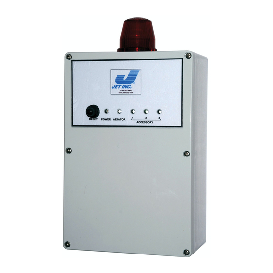
Jet Inc. Model 197 Control Panel
Installation and Users Manual
The Jet Incorporated Aerator control panel monitors and controls the operation of
Jet system aerators and additional components. The panel can be configured to
control single or dual aeration systems. A single aerator system controls the
operation of one aerator. A dual aerator system can control two aerators, or one
aerator and one re-aeration compressor.
In addition to the aerator control circuits, the control panel also contains the
following circuits or features:
• Two aerator/compressor control circuits
• Three auxiliary output circuits
• Three auxiliary input circuits with normally open or normally closed
selection
• One power indicator LED, and four additional error indicator LED's
• An alarm buzzer with circuit board provision for an alternate or externally
mounted buzzer
• A 9-position DIP switch for selection of configuration options
• User accessible reset switch and circuit board master reset switch
• Alarm mode Auto-Dialer power and control interface
• RS232 interface circuit
• Circuit board mounted power switch and fuse
Control Panel Features
A. Master Reset Button
B. Internal Horn
C. On/Off Switch
D. External Reset Button
E. Pump Power Supply Contacts
F. Alarm and Aerator Power Supply Contacts
G. Ground Buss
H. Central Alarm Beacon
I. DIP Switch Array
J. Auxiliary Alarm Settings (NC/NO)
K. Indicator Light Array
L. Auxiliary Alarm Contacts
M. Auxiliary Alarm Contacts
Jet Inc. 750 Alpha Drive Cleveland, OH 44143 www.jetincorp.com 800.321.6960
- - 1 - -
QA-SAL-132
REV 7/31/2013
Advertisement

Summary of Contents for Jet 197
- Page 1 Jet Inc. Model 197 Control Panel Installation and Users Manual The Jet Incorporated Aerator control panel monitors and controls the operation of Jet system aerators and additional components. The panel can be configured to control single or dual aeration systems. A single aerator system controls the operation of one aerator.
-
Page 2: Safety Instructions
Electrical supply must match nameplate specifications inside of the control panel. Incorrect voltage can cause fire, damage control panel and void the warranty. All single phase pump motors and aerators attached to model 197 Control Panels must be equipped with an automatic thermal protector, which opens the motor’s electrical circuit when an overload condition exists. - Page 3 5. Jet recommends burying cable and conduit at least two feet deep to prevent accidental damage to the external wiring 6. Proper procedures and solvents must be used to protect the integrity of the external wiring.
- Page 4 Make sure to check local codes and regulations regarding power requirements. 3. The Jet model 197 control panel is not equipped with knockouts for electrical conduit connections. Pilot holes must be drilled in the enclosure to allow conduit access into the panel.
- Page 5 13. If an integrated pump control is desired the model 197 control panel is equipped with an internal pump control relay. The pump should always be operated on an independent circuit.
- Page 6 5. Use a wrench, and tighten compression nut one (1) full turn past hand-tight. Do not over tighten fitting. *To prevent damage to conductors, conduit and fittings, do not twist Carflex during installation. Jet Inc. 750 Alpha Drive Cleveland, OH 44143 www.jetincorp.com 800.321.6960 QA-SAL-132 REV 7/31/2013...
- Page 7 Switch Nine On/Off Toggle Test Mode DIP switches one, two, and three will be fused in the ON position for 197 controls used with NSF Listed J-1500 series treatment systems which must have continuous aeration Jet Inc. 750 Alpha Drive Cleveland, OH 44143 www.jetincorp.com 800.321.6960...
- Page 8 If Auxiliary outputs 2 & 3 are enabled, the outputs are on during normal operation and off in an alarm condition. Jet Inc. 750 Alpha Drive Cleveland, OH 44143 www.jetincorp.com 800.321.6960 QA-SAL-132 REV 7/31/2013...
- Page 9 The circuit board mounted master reset switch causes a microcontroller reset. Jet Inc. 750 Alpha Drive Cleveland, OH 44143 www.jetincorp.com 800.321.6960 QA-SAL-132 REV 7/31/2013...
- Page 10 The power to the on-board circuitry and to the auxiliary outputs is fused and there is an on-board power switch for use by service or maintenance personnel. Jet Inc. 750 Alpha Drive Cleveland, OH 44143 www.jetincorp.com 800.321.6960 QA-SAL-132 REV 7/31/2013...
- Page 11 - - 11 - - Start Up Check List These procedures should be preformed by the Jet installer after all of the system components and aerators have been connected to the system. This test should only be conducted after the electrician has completed the panel installation and before occupation of the dwelling.
-
Page 12: Troubleshooting Guide
DIP not set to Check DIP setting Compressor compressor function • • Alarms not Functioning Automated reset Toggle test mode program active “ON” if instant (Normal Function) alarms desired Jet Inc. 750 Alpha Drive Cleveland, OH 44143 www.jetincorp.com 800.321.6960 QA-SAL-132 REV 7/31/2013... - Page 13 Electrical Wiring Diagram Refer to the wiring diagram below when connecting aerators, compressors, pumps, and auxiliary equipment to the Jet model 197 control panels. (Note: The location of the terminal blocks has been re-formatted for this manual and does not exactly correspond to the location of the terminal blocks on the circuit board) Jet Inc.
-
Page 14: Year Limited Warranty
All components must be returned by an authorized Jet distributor who is in good standing with Jet Inc. Jet Inc. may, at its option, elect to repair or replace the defective components, or refund the purchase price of the defective component(s).
Need help?
Do you have a question about the 197 and is the answer not in the manual?
Questions and answers
Alarm # 3 is going off was wondering what it was would be nice to mark them on the panel so I know in the future
Alarm #3 on the Jet 197 indicates an input error condition on one of the auxiliary inputs.
This answer is automatically generated