
Related Manuals for Tundra CM Series


Summary of Contents for Tundra CM Series
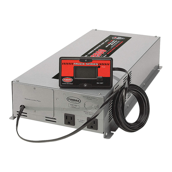
- Page 1 Owner’s guide: E-1000 / E-1500 / E-2000 HD-1200 / HD-1800 / HD-2500 HDI-1800 / HDI-3000 Install using Tundra CM Series installation kit Ask your retailer ! (See page 4 for details) www.tundrainternational.com...
-
Page 2: Table Of Contents
Table of contents INTRODUCTION ............................. 3 Disclaimer ................................3 Output waveform ..............................3 FRONT , REAR PANEL & REMOTE CONTROL ................3 PERMANENT INSTALLATION ......................4 Recommended material ............................. 4 Recommended tools ............................5 Where to install ..............................5 Mounting the inverter ............................5 Ground ................................ -
Page 3: Introduction
1 Introduction Congratulations! You have purchased one of the most sophisticated and reliable power inverters on the market today. Incorporating some of the latest technological developments, it will give years of trouble free operation for your truck, boat, R.V. or other. In order to get the most out of your inverter, the installation procedure must be followed carefully and it must also be properly used. -
Page 4: Permanent Installation
3 Permanent Installation The use of the Tundra International installation kits is strongly recommended. These complete installation kits are custom designed to maximize performance. It has been developed to promote safe installation and to help eliminate the difficult task of sourcing the requisite and right material. -
Page 5: Recommended Tools
Recommended tools Hand held crimping tool for terminal lugs * Mandatory Hollow punch or hole saw for metal Drill bit set for metal Screw driver set Open end wrench set Side cutters Power drill CAUTION! Before installation, make sure that the inverter is turned “OFF.” Where to install Your inverter should be installed in a location that meets the following requirements: - Dry:... -
Page 6: Ground
Use only covered, flexible, copper wires capable of withstanding temperatures in excess of 215° Fahrenheit. As included in our CM series kits, we recommend welding cables as the best size & type for connection between the batteries and your inverter. Keep the cable length as short as possible, no longer than 12 feet. -
Page 7: Preparation Of The Cable Connected To The Negative Side
Figure 5 : Fuse schema We recommend a “CNL” type fuse, mounted on a “CNL” fuse holder like to ones included in our CM series kits. Plug one terminal of the small and the long cable’s sections on the fuse holder, as illustrated in figure 5, and install the fuse. Without tightening them too much, the terminals must be solidly fixed onto the fuse holder, and must not be able to move around. -
Page 8: Connection Of The Batteries
Tighten the PVC strain relief nut on the cables until the rubber seal is properly compressed and the cables cannot move. Run the cables under your cab and cover them with plastic loom (included in our CM series kits) to prevent damage from road debris. -
Page 9: Microwave
Microwave The power rating used with microwave ovens is the cooking power which refers to the power being delivered to the food being cooked. The actual operating power requirement rating is 40% to 100% higher than the advertised cooking power. The actual power consumption is usually stated on the back of the microwave. -
Page 10: Troubleshooting Guide
Troubleshooting guide Problem Possible cause Solution Low output voltage (96 to 105 volts) Using a voltmeter which cannot Use a TRUE RMS reading voltmeter properly read the RMS voltage of a modified sine wave Fault indicator ON Low input voltage Not enough battery capacity Recharge batteries Improper installation. -
Page 11: Specifications
8 Limited one-year warranty Tundra International Inc. warrants its power inverters against defects in workmanship and materials for a period of one (1) year from the date of first consumer purchase. This warranty is given only to the first end-use purchaser of the product. - Page 12 The above information, along with the proof of the consumer’s purchase date, such as the duplicate of the receipt, must be included with the defective unit. TUNDRA INTERNATIONAL INC. 2041-A, Leonard-de Vinci, Sainte-Julie (Quebec) Canada J3E 1Z2 Tel : 450.649.2470 / 1.877.964.2582 Fax : 1.888.855.9834...
Need help?
Do you have a question about the CM Series and is the answer not in the manual?
Questions and answers