Tundra M1500 Installation Workbook
Power inverter system / sleeper trucks
Hide thumbs
Also See for M1500:
- Quick troubleshooting manual (21 pages) ,
- Installation manual (29 pages)
Table of Contents
Advertisement
Quick Links
Quick troubleshooting Guide
TUN-QTSG-0519-EN_A3
For power inverter models M1500 – M2000 – M2500 – M3000
ANNEX 3
INSTALLATION WORKBOOK
INSTALLATION WORKBOOK
POWER INVERTER SYSTEM / SLEEPER TRUCKS
MODELS: M1500 – M2000 – M2500 – M3000
TUNDRA INTERNATIONAL
ALL RIGHTS RESERVED
All rights reserved. No part of this publication may be reproduced or used without the prior written
permission of Tundra International. No liability can be accepted for any inaccuracies or omissions in
this publication, although every possible care has been taken to make it as complete and accurate as
possible. The right is reserved to make changes at any time without prior notice, and without incurring
an obligation to make such changes applicable to previously manufactured products. All information
contained in this publication is based on the latest product information available at the time of
publication. Illustrations and photographs in this publication are intended for reference use only.
© ALL RIGHTS RESERVED
APRIL 2017
Part No. TDIW-0417-EN
First Edition
PRINTED IN CANADA
Tel.: 450.649.2470 / 1.877.964.2582 Fax.: 1.888.855.9834
1
TUNDRAINVERTERS.COM
Advertisement
Table of Contents

Related Manuals for Tundra M1500


Summary of Contents for Tundra M1500
- Page 1 All rights reserved. No part of this publication may be reproduced or used without the prior written permission of Tundra International. No liability can be accepted for any inaccuracies or omissions in this publication, although every possible care has been taken to make it as complete and accurate as possible.
-
Page 2: Table Of Contents
Quick troubleshooting Guide TUN-QTSG-0519-EN_A3 For power inverter models M1500 – M2000 – M2500 – M3000 ANNEX 3 TABLE OF CONTENTS GENERAL INFORMATION FOREWORD SAFETY FIRST LIMITATIONS PRESENTATION PARTS LISTING INSTALLATION – INSIDE THE CAB DANGER – HIGH VOLTAGE THINK QUALITY... -
Page 3: General Information
Quick troubleshooting Guide TUN-QTSG-0519-EN_A3 For power inverter models M1500 – M2000 – M2500 – M3000 ANNEX 3 GENERAL INFORMATION 1-1 FOREWORD This manual is designed to be used primarily by trained mechanics in a properly equipped shop. However, it contains enough information to allow the owner to perform their own basic installation. A basic knowledge of mechanics and electricity, and the proper use of tools and workshop procedures is required in order to adequately and safely perform all tasks. -
Page 4: Limitations
Quick troubleshooting Guide TUN-QTSG-0519-EN_A3 For power inverter models M1500 – M2000 – M2500 – M3000 ANNEX 3 GENERAL INFORMATION 1-2 LIMITATIONS Electrical codes may vary depending on the region and type of installation. The electrical installation must comply with local and national standards, and must be carried out by a qualified professional. -
Page 5: Parts Listing
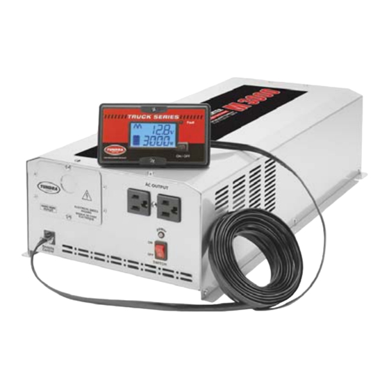
Quick troubleshooting Guide TUN-QTSG-0519-EN_A3 For power inverter models M1500 – M2000 – M2500 – M3000 ANNEX 3 GENERAL INFORMATION 1-3 PARTS LISTING Power Inverter 1. Power inverter 2. Multidata LCD monitor 3. Multidata LCD monitor cable 4. Monitor surface mount kit 5. -
Page 6: Installation - Inside The Cab
Quick troubleshooting Guide TUN-QTSG-0519-EN_A3 For power inverter models M1500 – M2000 – M2500 – M3000 ANNEX 3 INSTALLATION – INSIDE THE CAB 2-1 DANGER – HIGH VOLTAGE A power inverter produces an electrical current similar to that produced by conventional power grids. -
Page 7: Think Quality
Quick troubleshooting Guide TUN-QTSG-0519-EN_A3 For power inverter models M1500 – M2000 – M2500 – M3000 ANNEX 3 INSTALLATION – INSIDE THE CAB 2-2 THINK QUALITY QUALITY WORK RESULTS Tel.: 450.649.2470 / 1.877.964.2582 Fax.: 1.888.855.9834 TUNDRAINVERTERS.COM... -
Page 8: Where To Install The Inverter
Quick troubleshooting Guide TUN-QTSG-0519-EN_A3 For power inverter models M1500 – M2000 – M2500 – M3000 ANNEX 3 INSTALLATION – INSIDE THE CAB 2-3 WHERE TO INSTALL THE INVERTER The power inverter MUST be installed inside the cab, in the luggage compartment under the bed. -
Page 9: Ventilation
Quick troubleshooting Guide TUN-QTSG-0519-EN_A3 For power inverter models M1500 – M2000 – M2500 – M3000 ANNEX 3 INSTALLATION – INSIDE THE CAB 2-4 VENTILATION 1. Compared to other brands, Tundra International power inverters produce very little heat. A minimum clearance of 7 cm (2) at the ends is sufficient. -
Page 10: Determining The Best Location
Quick troubleshooting Guide TUN-QTSG-0519-EN_A3 For power inverter models M1500 – M2000 – M2500 – M3000 ANNEX 3 INSTALLATION – INSIDE THE CAB 2-5 DETERMINING THE BEST LOCATION 1. Using the power inverter and the template included in the CM installation kit, determine the best location to install the power inverter. -
Page 11: Floor Adapters - Pilot Holes
Quick troubleshooting Guide TUN-QTSG-0519-EN_A3 For power inverter models M1500 – M2000 – M2500 – M3000 ANNEX 3 INSTALLATION – INSIDE THE CAB 2-6 FLOOR ADAPTERS – PILOT HOLES 1. Using the template included in the CM installation kit, drill two 1/8″ pilot holes to validate your choice of location. -
Page 12: Floor Adapters - Hole Saw Drilling
Quick troubleshooting Guide TUN-QTSG-0519-EN_A3 For power inverter models M1500 – M2000 – M2500 – M3000 ANNEX 3 INSTALLATION – INSIDE THE CAB 2-7 FLOOR ADAPTERS – HOLE SAW DRILLING 1. Once the location is confirmed, drill the holes for the floor adapters based on the chart below. -
Page 13: Floor Adapters - Installation
Quick troubleshooting Guide TUN-QTSG-0519-EN_A3 For power inverter models M1500 – M2000 – M2500 – M3000 ANNEX 3 INSTALLATION – INSIDE THE CAB 2-8 FLOOR ADAPTERS – INSTALLATION 1. Remove the preinstalled nuts. 2. Insert one of the cables through the floor. -
Page 14: Power Inverter - Installation 2-9
Quick troubleshooting Guide TUN-QTSG-0519-EN_A3 For power inverter models M1500 – M2000 – M2500 – M3000 ANNEX 3 INSTALLATION – INSIDE THE CAB 2-9 POWER INVERTER – INSTALLATION 1. Place the power inverter in the designated location. 2. Using the included bolts, temporarily install the cables to the DC inputs of the power inverter to validate its position. -
Page 15: Connecting The 12 V Cables To The Power Inverter 2-10
Quick troubleshooting Guide TUN-QTSG-0519-EN_A3 For power inverter models M1500 – M2000 – M2500 – M3000 ANNEX 3 INSTALLATION – INSIDE THE CAB 2-10 POWER INVERTER – INSTALLATION (cont’d) Never use self-drilling screws to secure the power inverter to the truck. The thickness of the floor/walls does not provide the required resistance to vibration and to the weight of the power inverter. - Page 16 Quick troubleshooting Guide TUN-QTSG-0519-EN_A3 For power inverter models M1500 – M2000 – M2500 – M3000 ANNEX 3 INSTALLATION – INSIDE THE CAB 2-11 CONNECTING THE 12 V CABLES TO THE POWER INVERTER (cont’d) 3. Slide the rubber insulators on each of the cables to protect the inverter’s DC inputs.
-
Page 17: Grounding Verification
Quick troubleshooting Guide TUN-QTSG-0519-EN_A3 For power inverter models M1500 – M2000 – M2500 – M3000 ANNEX 3 INSTALLATION – INSIDE THE CAB 2-12 GROUNDING VERIFICATION Grounding a mobile power inverter is purely theoretical and has nothing to do with conventional grounding. Grounding a mobile... -
Page 18: Grounding Procedure (If Required)
Quick troubleshooting Guide TUN-QTSG-0519-EN_A3 For power inverter models M1500 – M2000 – M2500 – M3000 ANNEX 3 INSTALLATION – INSIDE THE CAB 2-13 GROUNDING PROCEDURE (if required) 1. Using a 12 V test lamp, find the “grounding” point closest to the power inverter. A metallic part connected to the vehicle chassis is ideal. -
Page 19: Multidata Lcd Monitor - Recessed Installation 2-14
Quick troubleshooting Guide TUN-QTSG-0519-EN_A3 For power inverter models M1500 – M2000 – M2500 – M3000 ANNEX 3 INSTALLATION – INSIDE THE CAB 2-14 MULTIDATA LCD MONITOR RECESSED INSTALLATION p. 2-14 SURFACE INSTALLATION p. 2-15 MULTIDATA LCD MONITOR – RECESSED INSTALLATION 1. - Page 20 Quick troubleshooting Guide TUN-QTSG-0519-EN_A3 For power inverter models M1500 – M2000 – M2500 – M3000 ANNEX 3 INSTALLATION – INSIDE THE CAB 2-15 MULTIDATA LCD MONITOR – RECESSED INSTALLATION (cont’d) We suggest validating your cutting measurements more than once so as to minimize the chances of damaging the panel.
- Page 21 Quick troubleshooting Guide TUN-QTSG-0519-EN_A3 For power inverter models M1500 – M2000 – M2500 – M3000 ANNEX 3 INSTALLATION – INSIDE THE CAB 2-16 MULTIDATA LCD MONITOR – SURFACE INSTALLATION (con’d) 3. Release the two parts of the monitor surface mount kit (included).
-
Page 22: Installation - Under The Cab
Quick troubleshooting Guide TUN-QTSG-0519-EN_A3 For power inverter models M1500 – M2000 – M2500 – M3000 ANNEX 3 INSTALLATION – UNDER THE CAB 3-1 CABLE PROTECTION 1. Before attaching the cables under the cab, cover them with the plastic loom included in the CM installation kit (from one end to the other). -
Page 23: Cable Routing 3-2
Quick troubleshooting Guide TUN-QTSG-0519-EN_A3 For power inverter models M1500 – M2000 – M2500 – M3000 ANNEX 3 INSTALLATION – UNDER THE CAB 3-2 CABLE ROUTING Routing the cables to the battery box is an important step. 1. Never suspend the power inverter cables to the truck’s cables or hoses. - Page 24 Quick troubleshooting Guide TUN-QTSG-0519-EN_A3 For power inverter models M1500 – M2000 – M2500 – M3000 ANNEX 3 INSTALLATION – UNDER THE CAB 3-3 CABLE ROUTING (cont’d) 2. You must make a “loop” to compensate for suspension movement in the cab. This loop must be located near the battery box.
-
Page 25: Batteries - Fuse Holder Installation
Quick troubleshooting Guide TUN-QTSG-0519-EN_A3 For power inverter models M1500 – M2000 – M2500 – M3000 ANNEX 3 INSTALLATION – UNDER THE CAB 3-4 BATTERIES – FUSE HOLDER INSTALLATION 1. Detach the cover from the base of the fuse holder by pressing firmly on both sides simultaneously, while lifting the cover to separate the two parts. -
Page 26: Batteries - Connecting Cables
Quick troubleshooting Guide TUN-QTSG-0519-EN_A3 For power inverter models M1500 – M2000 – M2500 – M3000 ANNEX 3 INSTALLATION – UNDER THE CAB 3-5 BATTERIES – CONNECTING CABLES Before connecting the cables to the batteries, make sure that the switch on the front panel of the power inverter is OFF. -
Page 27: Batteries - Securing Cables
Quick troubleshooting Guide TUN-QTSG-0519-EN_A3 For power inverter models M1500 – M2000 – M2500 – M3000 ANNEX 3 INSTALLATION – UNDER THE CAB 3-6 BATTERIES – SECURING CABLES To insure your safety: 1. The power inverter cables must be attached with plastic ties to the other cables on the top of the batteries.
Need help?
Do you have a question about the M1500 and is the answer not in the manual?
Questions and answers