Table of Contents
Advertisement
Quick Links
Advertisement
Table of Contents

Subscribe to Our Youtube Channel
Related Manuals for Riken Keiki GD-K88Di


Summary of Contents for Riken Keiki GD-K88Di
- Page 1 PT2E-1975 2-Wire Gas Detector Head GD-K88Di Operating Manual (PT2-197)
-
Page 2: Table Of Contents
Contents 1 Outline of the Product ............................3 1-1. Preface ..............................3 1-2. Purpose of use ............................3 1-3. Definition of DANGER, WARNING, CAUTION and NOTE ..............3 2 Important Notices on Safety ..........................4 2-1. Danger cases............................4 2-2. Warning cases ............................5 2-3. -
Page 3: Outline Of The Product
1-1. Preface Outline of the Product 1-1. Preface Thank you for choosing our 2-wire gas detector head GD-K88Di. Please check that the model number of the product you purchased is included in the specifications on this manual. This manual explains how to use the detector and its specifications. It contains information required for using the detector properly. -
Page 4: Important Notices On Safety
2 Important Notices on Safety 2-1. Danger cases Important Notices on Safety 2-1. Danger cases DANGER This detector is the intrinsically safe explosion-proof product with Zener Barrier. However, never attempt to detect a gas over the lower explosive limit. - 4 -... -
Page 5: Warning Cases
It can be used in a location where a combustible gas, or steam is present; however, it should be done carefully. Consult RIKEN KEIKI before operating the detector in such a location. External connection Before connecting the detector to the external control circuit, securely connect it to a protective grounding circuit. -
Page 6: Precautions
2 Important Notices on Safety 2-3. Precautions 2-3. Precautions CAUTION Do not use a transceiver near the detector. Radio wave from a transceiver or other radio wave transmitting device near the detector or its cables may disturb readings. If a transceiver or other radio wave transmitting device is used, it must be used in a place where it disturbs nothing. -
Page 7: Important Information About Explosion-Proof
2 Important Notices on Safety 2-5. Important information about explosion-proof 2-5. Important information about explosion-proof The detector is an explosion-proof product. The following provides information about the explosion-proof structure. Understand the information in this section thoroughly before using the detector. ... - Page 8 Others Confirm that no combustible gas is present around before opening the door of the unit. Never disassemble or modify the unit. Manufacturer: RIKEN KEIKI Co., Ltd. 2-7-6 Azusawa, Itabashi-ku, Tokyo, 174-8744 Japan www.rikenkeiki.co.jp The temperature range to maintain explosion-proof performance The temperature range to maintain gas detection performance is 0 to +40°C.
-
Page 9: Product Components
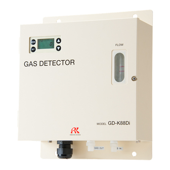
3 Product Components 3-1. Main unit and standard accessories Product Components 3-1. Main unit and standard accessories <Main Unit> (4) (5) (1) LCD display Displays the gas concentration. (Used at maintenance) (2) MODE switch Switches the mode from the detection mode to maintenance mode. Or exits the maintenance mode. - Page 10 3 Product Components 3-1. Main unit and standard accessories <Standard Accessories> Filter : Dust filter CF-8350 : Attached when the gas to be detected is CO (carbon monoxide). CF-8364 - 10 -...
-
Page 11: Names And Functions For Each Part
3 Product Components 3-2. Names and functions for each part 3-2. Names and functions for each part <Front View of Detector Unit> (10) (11) (12) (13) (14) (15) (8) Battery box Houses the battery for sensor backup. (9) Power switch Turns on/off the power of the unit. -
Page 12: How To Use
4 How to Use 4-1. Before using the detector How to Use 4-1. Before using the detector Not only the first-time users but also the users who have already used the alarm system must follow the operating precautions. Ignoring the precautions may damage the alarm system, resulting in inaccurate gas detection. 4-2. -
Page 13: Precautions For System Designing
4 How to Use 4-3. Precautions for system designing Do not install the detector in machinery which is not properly grounded. Before installing the detector in machinery, the machinery must be grounded properly. Do not install the detector in a place where interference gases exist around it. The detector must not be installed in a place where interference gases exist around it. -
Page 14: How To Install
4 How to Use 4-4. How to install 4-4. How to install A certain maintenance space needs to be secured in advance to allow the maintenance personnel to safely and properly perform maintenance of the gas detector function and performance. Be sure to secure this space during construction planning or installation. -
Page 15: Grounding
4 How to Use 4-5. Grounding 4-5. Grounding Connect the detector to your grounding terminal with the internal or external terminal. WARNING Before turning on the detector, never fail to connect it to a grounding terminal. Internal grounding terminal (M4) External grounding terminal (M4) For stable operation of the detector and safety, it must be connected to a grounding terminal. -
Page 16: How To Wire
4 How to Use 4-6. How to wire 4-6. How to wire CAUTION Be careful not to damage the internal electronic circuit when wiring. The connected cables must not be installed together with the motor power cables, etc. ... -
Page 17: System Connection Example
4-8. System connection example 4-8. System connection example 4-8-1. Example of connecting to indicator, DCS, PLC, etc. (non-explosion-proof system) Host system (DCS, PLC) Non-hazardous location GD-K88Di detector 4-8-2. Example of connecting to Zener Barrier, indicator, DCS, PLC, etc. Hazardous location Non-hazardous location... - Page 18 4-8-3. Example of connecting to Zener Barrier and indicator Non-hazardous location Hazardous location EC-5002/EC-592 Short circuit between (3) and (4). Zener Barrier A type grounding GD-K88Di detector 4-8-4. Example of connecting to insulating barrier, indicator, DCS, PLC, etc. Non-hazardous location Hazardous location Upper unit (DCS, PLC)
-
Page 19: How To Tube
The flow rate required for the detector is 500 cc/min or more. Consult RIKEN KEIKI for pumps, aspirators, etc. that draw gases externally. (3) Tube material Some gases to be detected have highly adsorptive or corrosive property. The tube material needs to be determined taking that point into consideration. - Page 20 4 How to Use 4-9. How to Tube 4-9-2. How to adjust sampling flow rate (1) Check required flow rate Turn the needle gradually to the left. Check that the FLOW is over the upper line. If not, adjust an external pump, etc. (2) Adjust flow rate ...
-
Page 21: How To Operate
5 How to Operate 5-1. Preparation for start-up How to Operate 5-1. Preparation for start-up Before connecting a power supply, read and understand the following precautions. Ignoring these precautions may cause an electric shock or damage the detector. Check that the detector is installed properly. ... -
Page 22: How To Start The Detector (Power-On)
5 How to Operate 5-3. How to start the detector (power-on) 5-3. How to start the detector (power-on) Before supplying power to the detector, check that the preparation for start-up is completed. Turn on the power switch located on the left side of the power terminal plate. <Initial Clear (approx. -
Page 23: Modes
5 How to Operate 5-4. Modes 5-4. Modes Details on each mode are provided as follows. CAUTION Do not change the settings if not necessary. Changing the settings without understanding the specifications may cause malfunctions. Mode Item LED display Details Detection mode Normal state... -
Page 24: Description Of Operation (Detection Mode)
5 How to Operate 5-5. Description of operation (detection mode) 5-5. Description of operation (detection mode) 5-5-1. Display operation The operation status of the detector is displayed on the LCD. Preparation Power-on LCD display (Example: Gas to be detected: CO) Initial clear (approx. - Page 25 5 How to Operate 5-5. Description of operation (detection mode) Negative value display The "-0" display is shown when the zero level drops to the negative (-) side by 10% or more of the full scale. WARNING Accurate gas detection cannot be performed with the negative value display. In this case, perform zero adjustment.
- Page 26 5 How to Operate 5-5. Description of operation (detection mode) 5-5-2. External output operation 4 – 20 mA transmission (1) Signal transmission method : Electric current transmission (non-isolated) (2) Transmission path : CVVS 2c 1.25 sq (3) Transmission distance : 500 m or less : 300 Ω...
-
Page 27: Description Of Operation (Maintenance)
5 How to Operate 5-6. Description of operation (maintenance) 5-6. Description of operation (maintenance) 5-6-1. Maintenance mode Enter the maintenance mode to perform each adjustment. Holding down the MODE switch for three seconds in the detection mode enters the maintenance mode. Holding down the MODE switch for three seconds in the maintenance mode returns to the detection mode. - Page 28 5 How to Operate 5-6. Description of operation (maintenance) 5-6-2. Zero adjustment This is used to perform the zero adjustment. NOTE If the zero calibration failed since the zero point was significantly fluctuated from zero, or by other reasons, it returns to 1-1 after FAIL is displayed. In this case, the zero adjustment has not been completed.
- Page 29 5 How to Operate 5-6. Description of operation (maintenance) 5-6-3. External output test This is used to check the transmission status by outputting a signal equivalent to gas concentration to the external device. WARNING Before starting the external output test (transmission test), provide a notification to the related sections so that they can prepare for false alarm.
-
Page 30: How To Exit
5 How to Operate 5-7. How to exit 5-7. How to exit To turn off the detector, turn off the power switch located on the left side of the power terminal plate. Then, turn off the power supply (24 VDC) to the detector. WARNING Before turning off the detector, decide whether the power can be turned off by checking the operation of the devices connected to the external output of the detector. -
Page 31: Maintenance
6 Maintenance 6-1. Maintenance intervals and items Maintenance The detector is an important instrument for safety. To maintain the performance and reliability of the detector, perform a regular maintenance. Continuing to use the detector without performing maintenance might cause the sensitivity degradation, thus resulting in inaccurate detection. - Page 32 Our qualified service engineers have expertise and knowledge on the dedicated tools used for services, along with other products. To maintain the safety operation of the unit, please use our maintenance service. Typical maintenance services are listed as follows. Please contact RIKEN KEIKI for more information. Main services Power supply : Check the power supply voltage.
-
Page 33: Gas Calibration Method
6 Maintenance 6-2. Gas calibration method 6-2. Gas calibration method Perform a calibration in each mode (zeroadjustment mode and span adjustment mode) using the calibration gas. <Zero Adjustment "2-1"> This is used to perform the zero adjustment. WARNING When the zero adjustment is performed in the atmosphere, check the atmosphere for freshness before beginning the adjustment. - Page 34 If there are mistakes, perform the span adjustment again. If the span adjustment cannot be performed even when there is no mistake or after recalibration, the gas sensor life might have expired. After turning off the power supply, please contact RIKEN KEIKI. - 34 -...
-
Page 35: Replacement Parts
NOTE The gas calibration using the standard gas is required after the sensor is replaced. Please make a request to RIKEN KEIKI. If adjustment to the standard gas concentration value fails even with the maximum sensitivity, it indicates that the gas sensor has come to the end of its life. The gas sensor needs to be replaced. - Page 36 For the stable operation of the detector and safety, ask a qualified service engineer to take care of replacement of the parts. Request the operation check from RIKEN KEIKI. NOTE In the case where the wireless energization time of the device is a total of more than half a year, the battery replacement for the sensor may be empty.
-
Page 37: Storage, Relocation And Disposal
CAUTION When using detector again after relocation or long-term storage, never fail to perform a calibration. For information on readjustment including a calibration, please contact RIKEN KEIKI. 7-3. Disposal of products When the detector is disposed of, it must be treated properly as an industrial waste in accordance with the local regulations. -
Page 38: Troubleshooting
If the detector shows a symptom which is not explained in this manual, or still has malfunctions even though remedial actions are taken, please contact RIKEN KEIKI. <Abnormalities on Unit>... - Page 39 Drifting of sensor Perform zero adjustment. output It is difficult to eliminate interference gases, such as Presence of solvents completely. Please contact RIKEN KEIKI to interference gas arrange removal filters. The reading rises (drops) and does not go A very small amount of the gas to be detected may back.
-
Page 40: Product Specifications
9 Product Specifications Product Specifications 9-1. List of specifications Model GD-K88Di Detection principle Electrochemical type Gas to be detected Toxic gases Concentration display 7-segment LCD (4 digits) Detection range Depends on the gas to be detected Detection method Suction method (suction unit is required separately) Suction flow 0.5L/min±10%... -
Page 41: Detection Principle
10 Definition of Terms Material SECC or SS304 Paint Bake-coated with melamine Outer color Munsell 2.5Y9/2 9-2. Detection principle An electrochemical type sensor electrolyzes a gas directly while maintaining the interface between electrode and electrolyte at a constant potential (bias voltage). A gas is electrolyzed by an electrolysis cell to which a certain potential (bias voltage) is applied, and the gas is detected from the electrolytic current generated at that time.
Need help?
Do you have a question about the GD-K88Di and is the answer not in the manual?
Questions and answers