Table of Contents
Advertisement
Quick Links
Advertisement
Table of Contents

Subscribe to Our Youtube Channel
Related Manuals for Riken Keiki GD-1DOX-AS


Summary of Contents for Riken Keiki GD-1DOX-AS
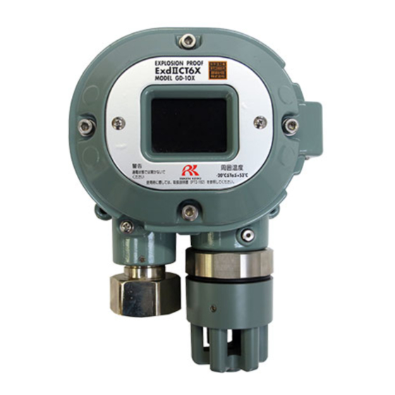
- Page 1 PT2E-2880 Fixed type Oxygen Detector Head GD-1DOX-AS Operating Manual (PT2-183)
- Page 2 Operating Precautions The detector detects oxygen in the atmosphere and prevents acid-deficient accidents due to acid-deficient air release or accidents due to excessive oxygen. Please fully understand the following points before using it, so that it can be used properly. 1.
-
Page 3: Table Of Contents
<Contents> 1 Outline of the Product ......................2 1-1. Preface ..........................2 1-2. Purpose of use ........................2 1-3. Definition of DANGER, WARNING, CAUTION and NOTE ..........2 2 Important Notices on Safety ....................3 2-1. Danger cases ........................3 2-2. -
Page 4: Outline Of The Product
Outline of the Product 1-1. Preface Thank you for choosing our fixed type oxygen detector head GD-1DOX-AS. Please check that the model number of the product you purchased is included in the specifications on this manual. This manual explains how to use the detector and its specifications. It contains information required for using the gas detector properly. -
Page 5: Important Notices On Safety
“9-1. List of specifications” for details.) Do not replace parts at your sole discretion but contact RIKEN KEIKI if the transparent window • has a crack or the explosion-proof joint surface is abnormal, or the clamping screw or bolt is changed, lost etc. -
Page 6: Warning Cases
2 Important Notices on Safety 2-2. Warning cases 2-2. Warning cases WARNING Need of grounding circuit Do not cut the grounding circuit or disconnect the wire from the grounding terminal. Defects in protective functions Before starting the detector, check the protective functions for defects. When seeming defects are found in the protective functions, such as protective grounding, do not start the detector. -
Page 7: Precautions
A dust filter to be used varies depending on the gas to be detected. For more information on dust filters, please contact RIKEN KEIKI. Observe the operating restrictions to prevent condensation inside the tube. Condensation formed inside the tube causes clogging or gas adsorption, which may disturb accurate gas detection. -
Page 8: Safety Information
2 Important Notices on Safety 2-4. Safety Information 2-4. Safety Information Necessary information for explosion proof construction of Model GD-1DOX. When oxygen is detected, the unit outputs a voltage corresponding to the oxygen concentration, and the indicator/alarm unit instructs the concentration, and when the concentration becomes equal to or lower than a preset concentration level (or higher), the alarm is activated by the indicator/alarm unit. -
Page 11: Product Components
3 Product Components 3-2. Names and functions for each part <Tubing Diagram> MC filter with flow monitor Needle valve Measuring Gas inlet Aspirator Compressed Gas/air outlet air inlet Tubing specification * The customer is required to provide the followings. (Alternate long and two short dashed line) Polyurethane tube (ø6 - ø8): X Polyurethane tube (ø4 - ø6): Y * Internal tubing has been arranged already. -
Page 12: How To Use
4 How to Use 4-1. Before using the gas detector How to Use 4-1. Before using the gas detector Not only the first-time users but also the users who have already used the detector must follow the operating precautions. Ignoring the precautions may damage the gas detector, resulting in inaccurate gas detection. 4-2. -
Page 13: Precautions For System Designing
4 How to Use 4-3. Precautions for system designing Do not install the detector in a place where maintenance of the detector cannot be performed or where handling the detector involves dangers. Regular maintenance of the detector must be performed. Do not install the detector in a place where the machinery must be stopped when maintenance is performed in its inside, where parts of the machinery must be removed to perform maintenance, or where the detector cannot be removed because tubes or racks prevent access to it. -
Page 14: How To Install
・Hexagon socket head cap bolt with strength class "A2-70" are used. When you lost or replace it, we recommend that you ask our local sales office nearest you. ・Grease specified by RIKEN KEIKI : BARRIERTA JFE 552 (manufactured by NOK KLUBER) If you can not prepare the specified grease, use one that meets the following requirements. -
Page 17: How To Wire
4 How to Use 4-6. How to wire NOTE • The following table shows an example of overall outer diameters of cables. Use them for reference. The overall outer diameters must be checked because they somewhat vary between manufacturers. Number of core CVV 1.25 mm CVV 2 mm CVVS 1.25 mm... -
Page 19: How To Tube
• To remove dust, do not forget to attach a dust filter in the middle of the tube. • You need to decide the length and material of the tube. Please contact RIKEN KEIKI for more information. -
Page 20: How To Operate
5 How to Operate 5-1. Preparation for start-up How to Operate 5-1. Preparation for start-up Before connecting a power supply, read and understand the following precautions. Ignoring these precautions may cause an electric shock or damage the detector. • Check that the detector is installed properly. •... -
Page 21: How To Start The Gas Detector
5 How to Operate 5-3. How to start the gas detector 5-3. How to start the gas detector Turn on the power switch of the indicator/alarm unit. Gas detection starts after the initial clear. The following decrease may occur during the measurement of the oxygen concentration, but it is not a failure. -
Page 23: Maintenance
6 Maintenance 6-1. Maintenance intervals and items Maintenance The detector is an important instrument for the purpose of safety. To maintain the performance of the detector and improve the reliability of safety, perform a regular maintenance. Continuing to use the detector without performing maintenance will compromise the sensitivity of the gas sensor, thus resulting in inaccurate detection. - Page 24 6 Maintenance 6-1. Maintenance intervals and items <About Maintenance Services> • We provide services on regular maintenance including span adjustment, other adjustments and maintenance. To make the calibration gas, dedicated tools, such as a gas cylinder of the specified concentration and gas sampling bag must be used.
- Page 26 6 Maintenance 6-2. Calibration method <Span Adjustment (AIR adjustment)> Adjust the reading to “20.9” at the indicator/alarm unit side under the condition that no gas is present around the detection point. If a gas is present around the detection point, collect fresh air in a gas sampling bag or the like and release it at the detection point for a certain time or so before starting the AIR adjustment.
-
Page 27: Calibration Method
(more than N2 99.9vol%) gas and wait until the indicator is stabilized. NOTE The span adjustment requires dedicated tools. We recommend the adjustment be performed by RIKEN KEIKI. Criteria Alarm delay time (time to alarm at 18% alarm point) ・・・・・・・・ within 5min Indicate accuracy ・・・・・・・・・・・・・・・・・・・・・・・・・・・・・・・・・・・・・・... -
Page 28: Replacement Parts
The operation must be checked after replacement by a qualified service engineer. For the stable operation of the unit and safety, ask a qualified service engineer to take care of replacement of the parts that operation must be checked. Request RIKEN KEIKI for operation check. NOTE •... -
Page 29: Storage, Relocation And Disposal
When using a relocated or stopped/stored detector again, never fail to perform a calibration. • For information on readjustment including a calibration, please contact RIKEN KEIKI. 7-3. Disposal of products When the detector is disposed of, it must be treated properly as an industrial waste in accordance with the local regulations. -
Page 30: Troubleshooting
8 Troubleshooting Troubleshooting The Troubleshooting does not explain the causes of all the malfunctions which occur on the detector. This simply helps to find the causes of malfunctions which frequently occur. If the detector shows a symptom which is not explained in this manual, or still has malfunctions even though remedial actions are taken, please contact our overseas sales department or local representatives. -
Page 31: Product Specifications
9 Product Specifications 9-1. List of specifications Product Specifications 9-1. List of specifications Model GD-1DOX-AS Detection principle Galvanic cell method Detection gas Applicable gas detector head GD-1DOX Detection method Aspirator suction type Sampling condition Equivalent to atmospheric pressure (compressed air: 0.1 - 0.7 MPa, maximum use amount: 3 L/min <converted into atmospheric pressure>) -
Page 33: Definition Of Terms
10 Definition of Terms Definition of Terms This is a principle of the sensor installed in the detector head. Galvanic cell type See "9-2. Detection principle" for details. A unit used to express the percentage of a specific substance (or gas) in a volume of vol% solution. - Page 34 Manual Log Rev. Amendment Issue data First issue (PT2-2880) 1/31/2022...
Need help?
Do you have a question about the GD-1DOX-AS and is the answer not in the manual?
Questions and answers