Table of Contents
Advertisement
Quick Links
Advertisement
Table of Contents

Related Manuals for KAYO MOTOR TT 125


Summary of Contents for KAYO MOTOR TT 125
- Page 1 KAYO MOTO TT 125 SERVICE MANUAL www.kayomoto.com...
- Page 2 This service manual is edited by KAYO. Please do not modify the content without authorization. Manufacturer has the right to improve and update the model’s structure and spare parts without notice. The model in the image may be different from the real model. PREFACE Thank you for choosing the 21 TD125 of KAYO MOTO as your choice for off-road recreation.
- Page 3 We must accept with humility. The contents of this manual are subject to change without prior notice due to vehicle improvement. The actual state of the vehicle shall prevail during maintenance. ZHEJIANG KAYO MOTOR CO., LTD. ENGINEERING OFFICE AUGUST. 2021...
-
Page 4: Table Of Contents
Content Meaning of Symbols and Technical Terms Suggestions for Daily Use Parts and Position 21 TT 125 Parts and Position Steel chassis VIN and Engine Number VIN Number Engine Number Specification Manipulation Front disc brake Throttle Ignition Stall Fuel tank switch... - Page 5 Disassembly and assembly of the chain Check and adjust the chain tension Inspect rear sprocket, engine sprocket and chain guide structure Inspection of the frame Inspection of the swing arm Inspection of the throttle cable Inspection of the handle bar Check and maintain the brake system Check the free stroke of the front brake handle Inspection of the disc brake...
- Page 6 Cylinder block and piston Main parameters and maintenance standards of cylinder block and piston Fault symptom and cause analysis Inspection of cylinder block Removal of piston and piston ring Inspection of piston and piston ring Installation of piston ring Installation of piston Installation of cylinder block Clutch, driving gear, driven gear, oil pump, shifting mechanism Main parameters and maintenance standards...
-
Page 7: Meaning Of Symbols And Technical Terms
Check the combination of main and auxiliary shafts Inspection of starting shaft Assembly of variable speed drum Installation of variable speed drum, main and auxiliary shaft, crankshaft and starting shaft Installation of crankcase Engine troubleshooting Motorcycle cleaning Storage of motorcycles The preparation of the motorcycle before long unused The main points of maintenance Vehicle tightening torque meter... -
Page 8: Suggestions For Daily Use
Therefore, in addition to the related matters that "DANGER", "WARNING" and "CAUTION" indicate, users must also have a basic knowledge of mechanical safety. If you are not sure to complete the entire maintenance and repair operation, please consult a more experienced senior technician before operation. Suggestions for Daily Use The vast majority of off-road motorcycle fatalities are caused by head injuries. -
Page 9: Parts And Position
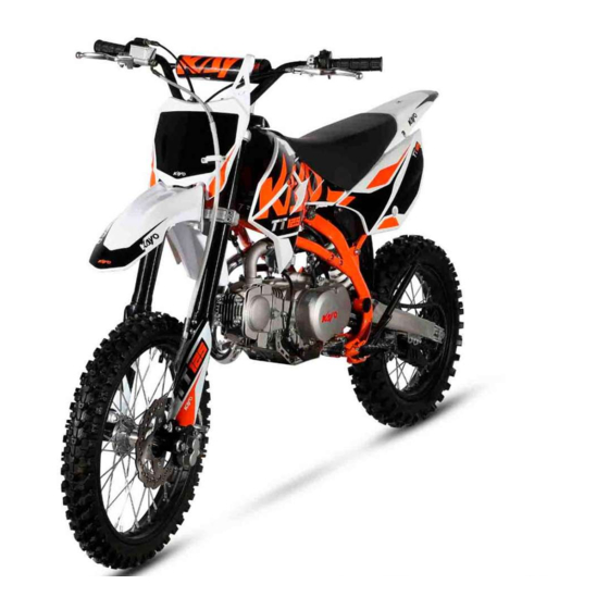
Parts and Position 21 TT 125 Parts and Position 10 11 12 13 15 16 Name Name Front fender Front fork Headlight Fuel tank Handlebar Carburetor Vent pipe Gear shift lever Fuel tank cap Pedal Fuel tank petcock Side stand... -
Page 10: Steel Chassis
26 27 28 29 Name Name Rear fender Rear brake caliper Muffler Swing arm Seat Rear brake oil cup Rear shock Brake pedal Steel chassis Upper clamp Lower clamp Muffler pipe Rear brake disc VIN and Engine Number VIN Number... -
Page 11: Engine Number
VIN Number of 21 TT 125 is carved on the frame of head pipe. Engine Number Engine Number of 21 TT125 is carved on the engine crankcase body behind gear lever. Specification TT125 size and quality parameters Length*Width*Height 1780×750×1120 (mm) -
Page 12: Manipulation
Engine parameter Engine type Single cylinder, four stroke, air - cooled, manual clutch Displacement 119.6cc Max power (kw/r/min) 5.6/8000 Max torque (N•m/r/min) 8.5/5000 Compression ratio 9.3:1 Gear shift type Constant mesh 4 speed gears Start method Kick Ignition system Chain #428;15T/41T Frame/shock/Braking/Wheel parameters Frame type... -
Page 13: Throttle
Front brake caliper Throttle The throttle is located on the right side of the handlebar and is controlled by right hand rotation. Turn the throttle up when turning the handle counterclockwise, then turn the handle back to the position after releasing the handle. Throttle Ignition The vehicle starting lever is located on the right side of the... -
Page 14: Gear Shifting
into the carburetor, so as to achieve control effect. Fuel tank switch Gear Shifting The shift lever is located on the left side of the engine, which is operated by stepping on and lifting the shift lever. The 21 TT125 engines are in four-gear gear with constant meshing. Gearshift lever Rear disc brake The foot brake pedal is located on the right side of the engine... -
Page 15: Notes Before Use
The 21 TT125 uses a single stand for parking. The single stand is on the left side of the motorcycle. When in use, straighten the motorcycle, kick the single stand to expand it, and tilt the motorcycle to the left so that the single stand touches the ground and supports the motorcycle. -
Page 16: Riding Guide
avoid the motorcycle running at the same throttle for a long time; after each hour of work, let the engine cool for 5 ~ 10 minutes; Avoid rapid acceleration, and the throttle cannot be either too large nor too small. 2. -
Page 17: Notes When Ignition
Notes when ignition Kick starting steps are as follows: 1.Turn the oil tank switch to the "ON" position; 2.Pinch the brake handle with the right hand; 3.Step the right foot on the starting lever vigorously; 4.The engine starts and process ends. Notes when starting 1.Before starting, inspection should be carried out first, including the state of the vehicle and the driver's clothing. - Page 18 Check and charge the battery ● ● ● Check the front disc brake pads ● ● ● Check the rear disc brake pads ● ● ● Check the front and rear disc brakes ● ● ● Check the brake hose for damage or leaks ●...
-
Page 19: Suspension System Setup
Final inspection: check if the vehicle is running safely and test run ○ ● ● ● ○ One time interval ● Periodic interval Note: This table is for reference only. Please adjust the specific cycle according to the use of the motorcycle. Warning: For inspection, adjustment and replacement of engine parts, please consult Kayo Suspension system setup Check the compression and rebound of the motorcycle when riding... -
Page 20: Measure Distance From Center Of Rear Wheel To Rear Fender In Riding Condition
The D1 value of 21 TT125 is shown as follows, TT125 10~40mm Measure distance from center of rear wheel to rear fender in riding condition The measurement procedure is as follows: 1.The rider rides the motorcycle (engine does not start) 2.Righten the motorcycle so that the center of the tire is perpendicular to the ground. -
Page 21: Check The Setup Of The Front Shock
Adjust the lock plate The spring preload of the rear shock can be controlled by adjusting the lock plate. Adjust the lock plate downward, the spring preload increases; Adjust the lock plate upward, the spring preload is reduced. Check the setup of the front shock The measurement procedure is as follows: 1.Place the whole motorcycle on the ground. -
Page 22: Disassembly And Assembly Of Front Shock Protector
When carrying out the related maintenance of the motorcycle, it is necessary to suspend the motorcycle to facilitate the disassembly and assembly of the parts. Disassembly and assembly of front shock protector Steps of disassembly and assembly of front shock protector are as follows: 1.Disassemble the fixing screws of front shock protector. -
Page 23: Disassembly And Assembly Of Clamp
Steps of disassembly and assembly of front shock are as follows: 1.Disassemble the front disc brake. 2.Disassemble the front wheel. 3.Loosen the fixing bolt on the clamp. 4.Remove the front shock. 5.Assembly shall be carried out in the reverse order of disassembly. -
Page 24: Disassembly And Assembly Of Front Fender
Disassembly and assembly of front fender Steps of disassembly and assembly of front fender are as follows: 1.Remove the bolts. 2.Remove the front fender 3.Assembly shall be carried out in the reverse order of disassembly. Disassembly and assembly of rear shock Check the rear shock and observe whether the spring has cracks. -
Page 25: Disassembly And Assembly Of Air Filter
Steps of disassembly and assembly of seat are as follows: 1.Remove the bolts in the back of the seat; 2.Remove screws fixing the seat and the oil tank; 3.Pull out the seat backward and upward. 4.Remove screws fixing the seat and the plastic parts. 5.Assembly shall be carried out in the reverse order of disassembly. -
Page 26: Disassembly And Assembly Of Fuel Tank
rust or impact, please replace the new one immediately. If the noise is too high or the engine performance degrades, replace the muffler. For the cleaning of the exhaust system, please consult with KAYO dealer. If you need to replace the muffler, please follow the following steps: 1.Unscrew the fixing nut of muffler. -
Page 27: Inspect Rear Sprocket, Engine Sprocket And Chain Guide Structure
its normal use. The chain tension can be adjusted according to requirements, as shown below: 1.The motorcycle is fixed so that the rear wheel is completely suspended; 2.Measure the distance between the back of the swing arm and the chain, the normal distance should be 30 ~ 40mm, about the width of two fingers. -
Page 28: Inspection Of The Throttle Cable
The swing arm inspection is carried out from the following aspects: 1.Check whether there are cracks on the surface of the swing arm; 2.Check whether there is deformation at the rear shock installation point on the swing arm; 3.Check whether the paint layer on the swing arm surface is damaged. -
Page 29: Check The Fluid Level Of Front Brake Disc
The disc brake inspection is carried out from the following aspects: 1.Check whether there are cracks, dents and other damage on the surface of the disc brake. 2.Measure the thickness of the disc and compare it with the limit thickness. If it is less than or equal to the limit thickness of the disc, the disc must be replaced immediately. -
Page 30: Check The Free Movement Of The Foot Brake
Check the caliper brake sheet thickness, if the thickness of the brake sheet is less than the minimum thickness, the brake sheet must be replaced. The minimum thickness of a brake sheet is1mm。 Note: the brake sheets should be replaced as a whole. If you are not sure to complete the replacement work, please go to the KAYO dealer,let the professional personnel to complete the replacement. -
Page 31: Tire Inspection And Maintenance
The steps to refill brake fluid are as follows: 1.Remove lid screw. 2.Remove the lid 3.Add brake fluid to appropriate position 4.Install back the lid DOT4 brake fluid is recommended. Check the rear brake friction plate Friction plate Check the thickness of the rear brake caliper brake disc, which should not be less than 1 mm. -
Page 32: Removal And Installation Of Rear Wheel
The front wheel is removed in the following order: Put the whole motorcycle on the stool and let it suspended Remove the front disc brake cover (skip this step if there is no cover) Loosen the front axle lock Hold the front wheel in place with one hand and slowly pull out the front axle with the other Remove the front wheel and place it in place Assembly shall be carried out in the reverse order of... -
Page 33: Engine Installation
Pull the adjacent spokes with your fingers to check whether the spokes lack tension. If any spokes are loose and weak, you must check all spokes of both wheels. If there are any problems, please contact the KAYO dealer. spokes Engine installation The steps of engine installation are as follows: ⑴... -
Page 34: Check Valve Clearance
Check valve clearance Check at initial 1000km and every 5000km. Excessive valve clearance will lead to valve noise, while too small valve clearance will cause engine power reduction and valve damage. Valve clearance should be checked according to the above specified mileage and adjusted according to the following steps: Remove the valve cover Unscrew the magneto plug and timing plug on the left front cover and turn the magneto rotor with a 14mm socket wrench until the piston reaches the top dead center of compression stroke (turn the magneto rotor until... -
Page 35: Adjustment Around The Engine
Adjustment around the engine Idle speed adjustment of carburetor Throttle screw The throttle screw and air screw are used to adjust the idle speed of the carburetor. The steps are as follows: 1.Turn the air screw clockwise until it reaches the top of its stroke and reverse one and a quarter turns;... -
Page 36: Check And Replace Spark Plug
Adjust the shift lever in the following order: 1.Loosen the fixing bolt of the shift lever 2.Remove the shift lever 3.Turn the shift lever to the appropriate position and load the spline 4.Tighten the shift lever fixing bolt Shift lever fixing bolt Check and replace spark plug Engine spark plug torque is 25 ~ 30N•m. -
Page 37: Lubricating Oil Inspection
Lubricating oil is an important factor affecting engine performance and life. It must be selected according to the regulations. It is forbidden to replace with ordinary engine oil, gear oil and vegetable oil. When the car leaves the factory, the transmission box is filled with 15W/40-SF grade oil. -
Page 38: Fault Symptom And Cause Analysis
value Free length of valve spring In32.75 Out35.55 In32.03 Out34.8 Intake valve 0.01~0.03 <0.01 or>0.03 Valve clearance Exhaust valve 0.01~0.03 <0.01 or>0.03 Camshaft base circle runout 0.02 0.04 Valve guide aperture φ5~φ5.012 φ5.035 Intake valve Φ4.97~φ4.985 Φ4.96 Valve stem diameter Exhaust valve Φ4.955~φ4.97 Φ4.94... -
Page 39: Timing Check
Left cover of cylinder Big inspect hole Timing check Timing mark of driven sprocket 1.Use special tools to rotate C100 six level magneto locking nut, at the same time through the small inspect hole on the left front cover to observe the magneto rotor on the timing scale line and the left front cover on the timing mark is correct;... -
Page 40: Check Valve Clearance
Valve cover 1.Remove the valve cover on both sides of the intake and exhaust of the cylinder head; 2.After removing the valve cover, check whether the thread is damaged and the sealing ring is damaged. If there is damage, use new parts when reassembling. Check valve clearance 1.Check that the magneto rotor timing mark is aligned with the timing mark on the left front cover and that the... -
Page 41: Inspection Of Valves And Valve Springs
The disassembling steps of cylinder head are as follows: 1.Remove valve cover. 2.Remove 2 bolts GB/T 5787/ M6x20 fastening the right cover of cylinder head; 3.Remove the right cylinder head cover and the right cylinder head cover gasket; 4.Take out the intake and exhaust rocker arm shaft, intake and exhaust rocker arm, limit plate and camshaft assembly;... -
Page 42: Inspection Of Camshaft Components
The inspection steps of rocker arm and rocker arm shaft are as follows: 1.Check whether the rocker arm arc surface is damaged, whether the valve adjustment screw and nut rotate flexibly, if wear and damage are serious, it is necessary to replace the rocker arm;... -
Page 43: Replacement Of Valve Guide
Measure the inner diameter of each valve guide with a dial indicator and record it. Maintenance limit value:φ5.035 mm Note: Before measuring the id of the valve guide, the carbon deposit in the valve guide should be completely removed. If the valve guide needs to be replaced, the valve seat should be re-ground surface treatment, and the valve inserted into the guide, observe its movement, and finally calculate the clearance between the valve rod and... -
Page 44: Installation Of Cylinder Head
through the threaded end of cylinder head rocker shaft hole smooth load limit in the plate and the rocker shaft hole, check rocker arm shaft load in place, can't interfere with AB bolt holes, Align the right cover of the sealing gasket and cylinder head with the mounting screw holes and mount them in place, and then tighten the bolts;... -
Page 45: Cylinder Block And Piston
the left front cover; (2) rotate the rotor of the magneto so that the rotor timing scale line "----" is aligned with the timing mark on the left front cover; (3) After the timing mark is corrected, observe the O engraving of the timing driven sprocket and the timing mark on the cylinder head is corrected;... -
Page 46: Fault Symptom And Cause Analysis
Second 0.1~0.25 ring Oil ring 0.2~0.8 First 0.03~0.06 0.08 ring side clearance Second 0.02~0.06 0.08 rinf Clearance between cylinder and 0.025~0.035 0.07 piston Outside diameter of piston pin φ12.994~φ13 φ12.985 Inner diameter of tip of connecting φ13.016~φ13.027 Φ13.035 Clearance between connecting rod 0.016~0.033 0.05 tip and piston pin... -
Page 47: Removal Of Piston And Piston Ring
Inspection steps of cylinder block are as follows, 1. Check whether the cylinder block is worn or damaged; 2. Measure the inner diameter of the cylinder block, take three positions, namely the top, middle and bottom of the piston stroke, and measure the two directions which are at right angles to each other. -
Page 48: Installation Of Piston Ring
Installation of piston ring Piston ring installation steps are as follows: 1. Clean the piston ring groove; 2. Install the piston ring; Note: (1) During installation, the piston and piston ring should be prevented from being damaged; (2) when installing the piston ring, one ring and two rings are literally facing the top of the piston, and the opening is staggered 180°, and the opening direction is toward the piston skirt direction;... -
Page 49: Clutch, Driving Gear, Driven Gear, Oil Pump, Shifting Mechanism
The installation steps of cylinder body are as follows: 1. Install cylinder block positioning pin, rectangular ring, new cylinder block gasket; 2. In the cylinder body, piston and piston ring surface evenly coated with a layer of oil; 3. The opening between the piston rings is staggered 120°... -
Page 50: Removal Of Right Trim Cover
handle The clutch CAM disengaging mechanism is damaged Oil pump failure Too low pressure in oil pressure The driving gear of oil pump is broken There are burrs in the chute of the clutch Difficult clutch operation cover Gear shifting arm bending The position of clutch cable is not adjusted Shift difficult correctly... -
Page 51: Disassembly Of Driving And Driven Gears
The disassembly steps of the clutch are as follows: 1. Remove the through-tubing and the through-tubing spring; 2. Remove four M5x10 cross countersunk screws that secure the clutch end cover; 3. Remove the clutch end cover and gasket; 4. Pry open the locked clutch stop washer, remove the large round nut fastening the clutch, take off the butterfly washer, clutch stop washer;... -
Page 52: Inspection Of Right Crankcase Cover
The disassembly steps of the shift mechanism are as follows: 1. Remove the shift arm parts; 2. Remove the fastening screw GB/ T70.1Mx35 of the five-star plate and remove the five-star plate; 3. Remove the positioning plate assembly fastening screws, and remove the positioning plate spring and the positioning plate assembly. -
Page 53: Check The Oil Pump
Check the oil pump Check the oil pump as follows: 1. Check whether the internal and external rotors of the oil pump are worn and damaged. If the wear and damage are serious, it is necessary to replace the new oil pump rotor assembly; 2. -
Page 54: Assembly Of Driving And Driven Teeth
finally load on the oil pump cover, install 2 M5x12 bolts, tighten. The washer of the oil pump is loaded on the shaft of the oil pump, and the spring washer of the oil pump is stuck on the pump. 3. -
Page 55: Assembly Of Right Crankcase Cover
Assembly of right crankcase cover The assembly of the right crankcase cover is as follows: 1. Assemble the clutch push rod smoothly into the corresponding hole on the right box cover; 2. Screw the clutch adjusting nut into the adjusting bolt after more than 3 teeth, and put the adjusting bolt into the CAM plate to the threaded hole and tighten it;... -
Page 56: Magneto, Timing Chain
Magneto, timing chain Matters needing attention ◆The removal and installation of the magneto, left cover and double teeth introduced in this section, as long as the left crankcase cover is removed, without removing the engine can be completed; ◆ For the inspection of magneto, refer to the methods in the section of battery charging system. Removal of left rear cover The steps for removing the left rear cover are as follows: 1. -
Page 57: Removal Of Starting Motor And Starting Sprocket
The removal steps of the magneto rotor are as follows: 1. Remove the locking nut of the magneto rotor; 2. Remove the rotor of the magneto with a special tool. Note: 1. When the rotor of the magneto is removed, it can only be removed with special tools, and it is not allowed to knock the rotor of the magneto;... -
Page 58: Removal Of Tensioning Arm, Tensioning Rod And Tensioning Roller
2. Remove the timing chain. Removal of tensioning arm, tensioning rod and tensioning roller The removal steps of the tensioning arm, tensioning rod and tensioning roller are as follows: 1. Remove the chain tensioning arm mandrel; Take out the tensioning arm; 2. -
Page 59: Installation Of Tensioning Arm, Tensioning Rod And Tensioning Roller
The inspection steps of magneto stator and rotor are as follows: 1. Check whether the magnetic tile of the magneto motor rotor is cracked or damaged, if so, it is necessary to replace the new magneto motor rotor; 2. Check to confirm that there is no foreign matter in the inner wall of the rotor, whether the roller of the rotor unidirectional roller falls off or is seriously worn, if there is, it is necessary to replace the new roller of the unidirectional roller;... -
Page 60: Transition Plate Installation
Transition plate installation Transition plate installation steps are as follows; 1. Mount two sealing rings 6.8×1.9 on the left crankshaft box; 2. Put the O-ring into the positioning pin, and then into the left body; 3. Install the transition plate on the left container and tighten the bolts. Installation of starting motor and starting sprocket The installation steps of starting motor and starting... -
Page 61: Installation Of Magneto Rotor
and tighten it. Note: The trigger locator plate should not press the wire harness. Installation of magneto rotor The installation steps of the magneto rotor are as follows: 1. Install the rotor of the magneto on the left crank; 2. Install GB/T6177 M10x1.25 nut on the left crank and tighten it. -
Page 62: Decomposition Of Crankcase
Fault symptom Cause analysis Remark The shift fork is bent and deformed Shift difficulty Gaskets and bolts of speed drum loose and loose The pawl of the shift gear is worn Groove-skipping The shift fork is bent or worn The needle roller bearing at the big end of the connecting rod is worn Crankshaft noise Connecting rod bending... -
Page 63: Left And Right Crankshaft Box Bearing Inspection
Check the crankshaft as follows: 1. Put the crankshaft on the V-shaped iron, and measure the large side clearance of the connecting rod with the thickness gauge. The limit value of maintenance: 0.4mm; 2. Use dial indicator to measure the runout of crankshaft diameter. -
Page 64: Inspection Of Starting Shaft
Check the main and auxiliary shaft combination as follows: 1. Check whether the gears of main and countershaft assembly have excessive or abnormal wear; 2. Check whether the retainers between gears are deformed or falling off. Inspection of starting shaft Check the starting shaft as follows: 1. - Page 65 The installation steps of crankcase are as follows: 1. Install the positioning pin into the corresponding hole in the left box, and then install the crankcase gasket on the left crankshaft box, close the right box on the left box, turn the box, the bolt GB5783 M6x16 and gasket 6×17×2 combination and then load into the variable speed drum threaded hole, then fasten the bolt with the T-shaped sleeve, and turn the secondary shaft when...
-
Page 66: Engine Troubleshooting
Engine troubleshooting For the engine to operate normally, the following four conditions must be met: 1. Good fuel: there is a certain ratio of combustible mixture in the cylinder. 2. Good spark: The spark plug gives off a strong spark at the right time. 3. - Page 67 adjusted Air intake pipe leaks Engine failure Incorrect ignition timing Carburetor oil level is too high The spark plug is damp Remove the spark plug carburetor choke closes too tightly The spark plug is dry The throttle is too high Improper adjustment of valve clearance or poor incorrect...
-
Page 68: Motorcycle Cleaning
Valve clearance is too Check whether the valve The valve is making an large has abnormal sound abnormal noise Valve worn Piston and cylinder worn Wear on small end holes Check whether abnormal There is an abnormal piston pins sound occurs sound in the cylinder connecting rods... -
Page 69: Storage Of Motorcycles
Storage of motorcycles The preparation of the motorcycle before long unused When you plan to store your vehicle and not use it for a long time, follow these steps: 1. Plug the exhaust port of the muffler cylinder; 2. Take out the battery. 3. -
Page 70: The Main Points Of Maintenance
After storing the motorcycle for a long time, please follow the following steps when putting it into use: 1. Take out the plug at the exhaust vent of the muffler cylinder. 2. Tighten the spark plug. 3. Fill the tank with fuel; 4. - Page 71 from the exhaust pipe, and then use the fan to blow on the mouth of the oil ruler for a few minutes. Warning: For safety, wrap the spark plug in a dry cloth to avoid jumping sparks. Clean tank snorkel and adjust air filter Incorrect mix of air and fuel duct exhaust open...
- Page 72 Gear groove worn Check gear and replace if necessary Gear damaged Replace the gear The displacement drum groove is Replace the shift drum damaged Check fork shaft and replace if Fork shaft worn necessary The position spring of speed selector is Replace the speed selector position damaged spring...
- Page 73 Rim bias Contact KAYO Service Center Whether the front wheel bearing is Check the bearing and replace it if worn necessary Check the spokes and adjust the tension Misalignment of motorcycle if necessary Check clearance of pressure bearing of Excessive tolerance of steering shaft steering shaft Steering shaft nut loose, handlebars Check and retighten...
-
Page 74: Vehicle Tightening Torque Meter
Vehicle tightening torque meter Note: Before installing the thread, apply anti-rust grease on the thread and bonding surface. Item Fastener specification Torque(N•m) Front brake caliper bolts M8×40 full thread 20~32 Directional column cover silver chrome finish Upper pressure block screw M8×25 20~32 Front disc brake disc bolts...
Need help?
Do you have a question about the TT 125 and is the answer not in the manual?
Questions and answers
Здравствуйте, какой смазкой лучше смазывать цепь ?
The best lubricant for the chain of the KAYO MOTOR TT 125 should be chosen according to the correct lubrication method and appropriate for the working conditions. Regular lubrication is required, and alternately wet and dry conditions shorten the chain's service life, so a suitable lubricant for those conditions should be used.
This answer is automatically generated
Здравствуйте, какое изначальное положение винта качества смеси у kayo tt 125 2024 года?