Table of Contents
Advertisement
Advertisement
Table of Contents

Related Manuals for KAYO MOTOR K6-R


Summary of Contents for KAYO MOTOR K6-R
- Page 1 KAYO MOTO K6-R Service Manual W W W . K A Y OMOTO.US - 1 - www.kayomoto.us...
-
Page 2: Table Of Contents
This service manual is edited by KAYO Please do not modify the content without authorization。 Manufacturer has the right to improve and update the model’s structure and spare parts without notice. The model in the image may differ slightly from production models. Preface This service manual is edited by KAYO Please do not modify the content without authorization。... - Page 3 Fasteners torque table……………………………………………………………………………………………….11 Operating instruction……………………………………………………….12 Check before use……………………………………………………………………………………………....13 starting steps………………………………………………………………………………………….......16 …………………………………………………………………………………………………..17 run-in period cleaning……………………………………………………………………………………………………....17 …………………………………………………………………………………………....18 Storage and usage maintenance…………………………………………………………18 Routine Periodic maintenance table………………………………………………………………………………………..19 Specific maintenance content……………………………………………………………………………………..20 Vehicle settings……………………………………………………………….29 Specific settings and methods………………………………………………………………………………....29 Vehicle troubleshooting……………………………………………………...31 Possible faults and troubleshooting methods……………………………………………………………………..31 Engine maintenance manual………………………………………………..36 Cylinder head and valve…………………………………………………………………………………………..42 Cylinder and piston………………………………………………………………………………………………..46 Clutch, drive tooth, overrunning clutch, oil pump,and shift mechanism..............51...
-
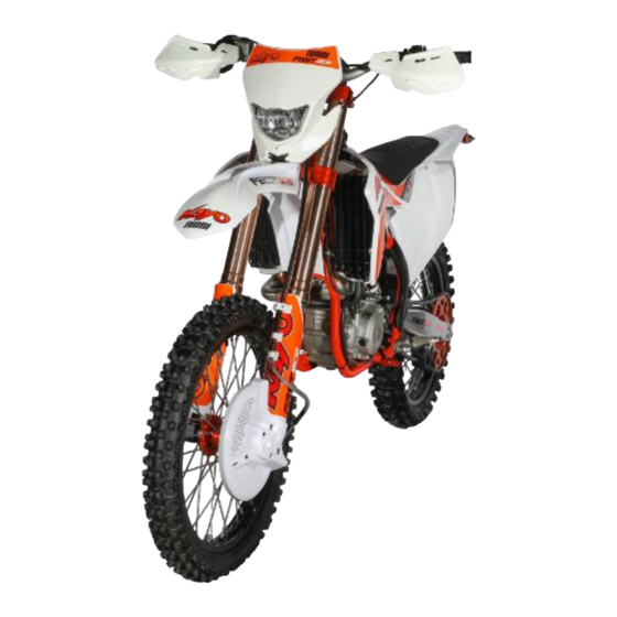
Page 4: Vehicle Profile
Vehicle profile Vehicle component and location ○ ○ ○ ○ ○ ○ ○ ○ ○ ○ ○ ○ ○ ○ ○ ○ ○ Name Name Front fender Front brake caliper Headlight Front fork Handlebar Fuel tank Vent pipe Carburetor Fuel tank cap Gear shift lever Fuel tank petcock Pedal... - Page 5 ○ ○ ○ ○ ○ ○ ○ ○ ○ ○ ○ ○ ○ Name Name Taillight Rear brake caliper Muffler U-shape rocker arm Seat Triangle rocker arm Rear shock Rear brake oil cup Start lever Brake pedal Radiator Muffler pipe Rear brake disc - 5 - www.kayomoto.us...
-
Page 6: Vin Number
VIN number ○ ○ ○ ① VIN number ② Frame plate ③ Engine number - 6 - www.kayomoto.us... -
Page 7: Specifications
Specifications Vehicle dimension and mass parameter Length×Width×Height 2180×820×1254 (mm) Wheelbase(mm) 1488 Curb weight(kg) Tire type Front 80/100-21;Rear 100/90-19 Seat height(mm) Ground clearance(mm) Fuel capacity(L) Engine Engine type Single cylinder, 4-stroke, water cooling, 4 valves, SOHC, w/ balance shaft Clutch type Wet multiple disc Bore×Stroke 77×53.6mm... - Page 8 Front 1.60×21,rear 2.15×19;7050 alloy,forging CNC hub Double piston pump hydraulic brake system,disc Φ240mm,CNC lever Front brake Single piston pump hydraulic brake system, disc Φ240mm,forging brake pedal Rear brake Others Air filter type Sponge filter type Person capacity 1 person(driver) - 8 - www.kayomoto.us...
-
Page 9: Circuit Diagram
Circuit diagram Fasteners torque table Caution: please apply anti-rust grease on the thread and joint surface before installing the thread. Item Fasteners specification Torque(N•m) Front brake caliper screw M8×40 full thread 20~32 Front brake guard screw M6×16 7~11 Steering stem screw Aluminum, silvery Upper raisers assembly screw M8×30... - Page 10 Rear disc bolt M6×16 7~11 Rear sprocket screw M8×31 10.9 level 27~35 Rear wheel axle nut M22×1.5 452~550 Rear brake disc guard bolt M6×12 7~11 Brake pedal head screw M5×10 full thread 4~7 Brake limit bolt M8×20 full thread 20~32 Rear brake pump bolt M6×16 full thread 7~11...
-
Page 11: Operating Instruction
Operating instruction Check before use Please check the following items each time. ○ 1.Fuel level Open the tank cap and shake the handlebars, and observe the fuel the level of the tank. If fuel is low, please add fuel. 2. Fuel tank switch There are three positions of the fuel tank switch in this motorcycle, from top to bottom: RES (the auxiliary fuel tank is open), OFF (the fuel tank switch is closed), ON (the fuel tank switch is open).If the fuel tank... - Page 12 Brake fluid level. Through the brake fluid sight glass (①and②), checking the brake fluid in the brake master cylinder. If brake fluid level is lower than half of the observation hole, or "LOWER" position, then add brake fluid. ○ ○ Note: brake fluid should be replaced annually even if the motorcycle has not been used for a long time.
- Page 13 8、check tire pressure Use the pressure gauge to check whether the tire pressure level is in line with the standard of this motorcycle, if there is often a small pressure problem, check the tire flats and any punctures . recommended pressure Front :1 bar(15PSI)...
-
Page 14: Starting Steps
. Check the battery charge. Note: when the vehicle starts, check the lights. the brake should be applied to Note: these pre ride checks won't take much time, but it can help you prevent the vehicle from starting in develop good riding habits and make your daily riding easier and safer. gear. -
Page 15: Cleaning
Engine break-in period Motorcycle engines have many parts that make relative movements, such as pistons, piston rings, cylinder blocks, and meshing transmission gears. Therefore, in the initial stage of use, the engine must be regularly run-in. The running-in can adapt the moving parts to each other, correct the working gap, and form a good smooth friction surface that can withstand large loads. - Page 16 Warning: Never use high pressure water to clean the vehicle. Avoid direct contact of water flow with coils, pipe plugs, carburetor or any electrical components. Warning: do not use high pressure water to clean it. Avoid making the water directly touch with coils, pipe plugs, carburetors or any electrical components.
-
Page 17: Routine Maintenance
Routine Maintenance Every 30 hours operating Every 20 hours operating Every 10 hours operating/after every race Once after 1 operating ● ● ● Check and charge the battery ● ● ● Check the front brake linings ● ● ● Check the rear brake linings ●... -
Page 18: Specific Maintenance Content
○ ● ● ● Check the screws and nuts for tightness ○ ● ● ● Change the fuel screen ○ ● ● ● Check idle ○ ● ● ● Final check: Check the vehicle for safe operation and take a test ride ○... - Page 19 5.Air filter The air filter should be checked on time, as follows: Remove the seat cushion; Remove the air filter cover; Check the air filter. 6.Carburetor Installation is performed in the reverse order of removal. Throttle screws and air screws allow idle sp carburetor.
- Page 20 undoubtedly a very dangerous behavior.Normal throttle cable should have at least 10mm free travel.Start the engine and turn the handlebars, if the engine stops or accelerates due to handlebar’s movement, then the throttle cable is not properly adjusted or damaged.Make sure the throttle cable is OK before driving the motorcycle.
- Page 21 follows: Start the engine and let it run for 5 minutes to mix any sediment with the oil; Stop the engine and place the container under the engine; Unscrew the oil drain bolt and place the motorcycle above the container, so that all the oil can be smoothly discharged;...
- Page 22 cause the boots to slip on the pedal, affect riding. ○ 13、Coolant liquid The coolant absorbs excess heat from the engine and transfer to the air through the radiator. If there is not enough liquid in the coolant tank to cool the engine, the engine will be damaged due to overheating.Therefore, before each use, must check the level of the coolant to ensure the normal cooling.
- Page 23 the liquid is brown, the steel or iron part of the cooling system is corroded.Beyond these, the cooling system is normal. Warning: check the sealing ring in the cooling system. If it is damaged, it should be replaced. 14、Tank tube and fin strip Check whether the coolant water tank pipe①...
- Page 24 accidents. The replacement should be carried out after consulting the dealer of KAYO. 17、brake fluid The brake fluid must be checked and replaced periodically. If the brake fluid is mixed with water, soil or other particles, the brake fluid should also be replaced.
- Page 25 Check the front shock absorber, if necessary, you can vent the front shock absorber through the exhaust screw① . Note: when venting, pls place the motorcycle on a fixed bracket so that the front wheels can be completely suspended. After putting the motorcycle on the ground, press the handlebar to test whether it is sensitive to rebound after pressing down.
- Page 26 26、Conventional lubrication Every part of the vehicle needs to be lubricated regularly. After cleaning the vehicle with pressure water, the motorcycle also needs to be lubricated. Before lubricating the components, the rusty components need to be cleaned with antioxidants and remove any remaining oil, grease and dirt. Generally, the components that need to be lubricated are: ○...
- Page 27 28、Chain inspection The chain transmits the power output from the engine to the wheels, so that the motorcycle can move normally, which is an important part of the motorcycle. Therefore, the chain needs to be checked and maintained frequently to ensure its normal use. The chain tension can be adjusted according to requirements, and the steps are as follows: Fix the motorcycle so that the rear wheels are completely suspended;...
- Page 28 The minimum height of the pattern is 3 mm. Checking the tire pressure: Use a barometer to check the pressure inside the tire. Our recommended tire pressure is: front 1.0bar; rear1.0 bar. 30、Battery check Remove the motorcycle seat cushion and use a multimeter to check the voltage and output current of the positive and negative terminals of the battery.
-
Page 29: Vehicle Settings
Vehicle settings Specific settings and methods Carburetor settings The carburetor is an important factor that affects the performance of motorcycles. Our company chose the NIBBI racing version PWK carburetor. By changing the opening of the carburetor valve, the composition of the mixture can be adjusted, thereby affecting the performance of the engine. - Page 30 Front shock absorber settings Frame, engine and shock absorber are three important factors that affect motorcycle performance. The frame and engine cannot be adjusted directly, but the shock absorber can be set according to the user's usage. Our company chooses FASTACE inverted double adjustable front shock absorber, whose damping hardness can be adjusted.
-
Page 31: Vehicle Troubleshooting
Vehicle troubleshooting Possible faults and troubleshooting methods In the following, we will list the problems that occur during your use, find out their possible causes, and give general solutions. Problems Reasons Solution Engine crank does not turn Crank stuck Contact dealer Cylinder, piston, connecting rod Contact dealer... - Page 32 still has water, you can drain the oil in the crankcase and observe its color. If it is white, it means there is still water. If the cylinder enters water, step on the starter lever a few times with the flame off.
- Page 33 Damaged worn crankshaft Contact KAYO dealer bearings Engine sound abnormal Ignition problem Contact KAYO dealer See”engine over heating”part overheat Tempering of the exhaust pipe Carbon deposits in the combustion Contact KAYO dealer chamber Gasoline not good quality Change fuel The spark plug is in poor condition Replace with new correct spark plug or has incorrect specifications Exhaust system gasket...
- Page 34 position Fork oil viscosity is too high Change the viscosity of the fork oil Fork bend Contact KAYO dealer Excessive tire pressure Check tire pressure and adjust to proper air pressure adjustment error Readjust shock absorption Damping too soft Fork oil level is insufficient Add the right amount of fork oil Note: add the same oil Fork oil viscosity is too low...
- Page 35 Problems with the fork Contact KAYO dealer Vehicle misaligned Readjust the spoke tension and contact KAYO dealer if necessary Brake failure brake discs wearing Replace the brake disc Insufficient brake fluid Replenishing brake fluid Brake fluid deterioration Change the brake fluid Damaged piston Contact KAYO dealer Wear of brake pads...
-
Page 36: Engine Maintenance Manual
Engine maintenance manual Cylinder head and valve Maintenance instructions Inspection of the cylinder head Troubleshooting Inspection and grinding of valve seat Cylinder head cover disassemble Examination of valve guide cylinder head disassemble Valve guide replacement Disintegrate cylinder head cover Measure the width of the valve seat contact Disintegrate the cylinder head surface Inspection of valves and valve springs... - Page 37 Troubleshooting Low air pressure in the cylinder: Exhaust smoke: 1.Valve 1. Worn valve guides ---------- Incorrect valve clearance adjustment 2. Oil hood leaks or is damaged ---------- the valve is not tight 3. Cylinder head pad leakage ---------- Incorrect timing of gas distribution 4, the piston ring gap is too large ---------- Broken valve spring 2.Cylinder head...
- Page 38 cylinder head disassemble 1Remove NC250 cylinder head sealing rubber sleeve, NC250 camshaft baffle plate; 2. Remove GB / T16674 small plate bolt M6 × 16 and ZS50 fixed Bit plate washer 6.5 × 1.5 × 18; 3. Remove 2 GB / T16674 small disk bolts for tightening the tensioner M6 ×...
- Page 39 Disintegrate cylinder head cover 1. Remove the two NC250 rocker shaft positioning plate bolts M14 × 1 from the cylinder head cover. 2. Remove the inlet and exhaust rocker arm shafts and the inlet and exhaust rocker arms. Disintegrate cylinder head Use the valve remover to press down the valve spring and remove the valve lock clip;...
- Page 40 Check the valve for bending, burns, or abnormal wear on the valve stem, and measure the valve stem outer diameter. Maintenance limit value: Intake: φ4.96mm Exhaust: φ4.94mm Contact surface width maintenance limit value: 1.5mm Note: If the valve contact surface is rough, the abrasion is uneven, or the valve seat is not in proper contact, the sealing performance cannot be guaranteed, and the valve should be replaced.
- Page 41 1. Check whether the cylinder head is well sealed. If poorly sealed, replace a new cylinder head or valve. 2. Check if spark plug hole and valve seat has cracks Check the cylinder head for deformation. Measure the flatness with a knife edge ruler and a plug ruler. Inspection and grinding of valve seat Clean the carbon deposits in the combustion chamber completely, then smear a thin layer of red printing oil evenly on the valve seat.
- Page 42 Inspection of valve pipe Measure the inner diameter of each valve pipe with a dial indicator and record them. Maintenance limits: Air intake:φ5.035 mm Exhaust:φ5.035 mm Note: Clean up carbon deposit before measuring pipe inner diameter. If replace the valve pipe, the valve seat shall be re-ground and each valve shall be inserted into the pipe to observe its movement.
- Page 43 3.Then press down the valve spring with the valve discharger, and then put the air lock clamp into the valve spring seat. note: In order to prevent the valve spring from permanent deformation, the spring cannot be compressed excessively. 4.Check whether the air lock clamp assembly is in right place 5.Check the air tightness of the assembled cylinder head.
- Page 44 1. Replace new cylinder head seal, then install locating pin. 2.Install the cylinder head on bolts A and B, then place the nut washers of ZS500A and B bolts on bolts A and B, and then install the nuts of ZS500A and B bolts on bolts A and B and tighten them.
- Page 45 tensioner spring, seal and bolts in place. 6.Put the ZS500 positioning plate washer on the GB/T16674 bolt M6×16, tighten the bolt to the camshaft, install the NC250 camshaft baffle into the baffle groove of the cylinder head, and finally put the NC250 cylinder head sealant set into the sealant groove of cylinder head..
-
Page 46: Cylinder And Piston
Cylinder and piston Maintenance instructions piston removal Trouble shooting piston and piston ring inspection Cylinder disassembly piston ring mounting Cylinder body inspection piston mounting Cylinder body mounting Maintenance instructions General Note: ● Make sure the oil hole near left body AB bolt is working well before installing cylinder. ●... - Page 47 Trouble shooting Low or unstable compression force: Overheat: 1.Cylinder or piston ring is worn 1.too much carbon deposits in piston Remove excess black smoke: Knock or abnormal noise: 1.Cylinder, piston or piston ring worn 1.piston or cylinder is worn 2.Incorrect piston ring mounting 2.too much carbon deposits 3.The piston or cylinder walls are scratched or scratched...
- Page 48 Disassembly of piston Remove piston pin washer with needle-nose pliers and remove piston pin and piston. note: Do not drop the piston pin washer into the crankcase while removing it. Inspection of piston and piston pin Remove piston ring; note:do not damage piston ring Measure the clearance between piston ring and piston ring groove Maintenance limit:first ring:...
- Page 49 Measure inner diameter of piston pin hole Maintenance limit:φ16.015 mm Measure the outer diameter at a height of 7 mm from the piston skirt Maintenance limit:φ76.94 mm Calculate the clearance between cylinder and piston. Maintenance limit:0.1mm Measure outer diameter of piston pin Maintenance limit:15.99 mm Calculate the clearance between piston pin and piston.
- Page 50 3.The gap between the rings in the oil ring shall be matched with the gap between the rings. When installing the oil ring, install the baffle ring first and then install the side guide. Piston assembly Install piston, piston pin and new piston pin ring.
-
Page 51: Clutch, Drive Tooth, Overrunning Clutch, Oil Pump,And Shift Mechanism
Clutch, drive tooth, overrunning clutch, oil pump and shift mechanism Maintenance instructions Inspection of drive gear troubleshooting Inspection of overrun clutch Disassembly of water pump impelle Inspection of big start gear Disassembly of right crankcase cover Inspection of right body oil pump Disassembly of water pump shaft, Inspection of starter motor and water seal components and oil seal... - Page 52 End clearance between rotor assembly ---- 0.04~0.1 and cover plate Troubleshooting The bike will move slowly when the clutch clutch slips when accelerating: 1.Insufficient free travel is released: 2.Disc worn 1. Large free travel. 3.Clutch plate bending 2.bent clutch plate Handle bar with too much pressure:...
- Page 53 1. First drain the oil (remove the oil filter cover on left and right sides, take out the combination of oil filter in the box, and wait for the oil in the box to run out); 2. Remove the right cover connection screw and remove the right crankcase cover.
- Page 54 1. Remove carrier gear and gear combination washers from oil pump. 2. Remove carrier gear washer, carrier gear and gear combination from oil pump. Remove three GB/T16674 bolt M5*18 from oil pump plate, then remove plate combination and rotors combination. note:...
- Page 55 1. remove bolts GB/T70.1 M6×35 and five-star plate. 2. Remove the gear shifting arm components. 3.Remove the fixed plate combination screw, fixed plate washer and fixed plate combination.. Inspection of right crankcase 1. If the crankshaft oil seal of right crankcase worn, replace it. note:...
- Page 56 Inspection of clutch friction disc If the clutch friction disc appears scratch or fade marks, it should be replaced. Measure the thickness of each clutch friction disc. Maintenance limit: 2.85mm Check if there is any distortion on the surface of the clutch follower, check...
- Page 57 Inspection of active teeth Check if the active teeth was damaged, if the wear and damage is serious, need to replace the new active teeth. Inspection of free wheel device Remove the wedge at the end of the free wheel device and check for wear and damage condition of the wedge.
- Page 58 Inspection of starting motor and double gear Check whether the gear slot of the starting motor and the double gear are damaged Inspection of change gear device Check whethe the positioning plate roller is worn and if the roller rotation is inflexible. Assembly of the starting shaft Install the starting shaft into the corresponding starting shaft hole of the right body.If only electric start without this step.
- Page 59 Assembly of free-wheeling clutch Install the wedge on the outer cover of the free-wheeling clutch. When assembling, please note not to reverse the wedge. Installation of starting gear and overrunning clutch 1. Install the big gear washer to the right crank. 2.
-
Page 60: Magnetos And Balancing Main And Driven Gear
Assemble the starting motor in place after evenly applying oil to the slot end of the starting motorand fasten with 2pcs of GB/T16674 small plate boltsM6×25.Fastening torque 11~13N·m Installation of right crankcase cover 1. Remove the old right crankcase gasket, install the new gasket, mount the right crankcase cover in place and fasten with 10pcs of GB/T16674 small disc bolts M6×30.Fastening torque:11~13N·m 2. - Page 61 Removal of the left crankcase cover Remove the left front cover fastening bolt and remove the left crankcase cover. Removal of the stator of the magneto 1. Remove 2pcs of GB/T818 sensing screws M5×10(color zinc) ML35-HIPERfastening screws ; 2, Remove the 2pcs of GB/T70.1 screws of the stator coil M5×30 fastening screws, then remove the magneto stator combination from the left crankcase cover.
- Page 62 1. Remove the timing chain and the chain tensioning plate, and then remove the balancing active tooth locking nut and active tooth locking nut washer respectively; 2. Remove crank shaft timing active sprocket and balance active gear; 3. remove the balance driven tooth lock nut and CB125 clutch disc washer ;...
- Page 63 Inspection of the left body oil pump 1. Check if the left body oil pump rotor assembly is worn or damaged ; 2. Check if the left body oil pump cover plate is worn or damaged. Left oil pump cover Left Engine oil pump rotor combination Installation of the left body oil pump...
- Page 64 Installation of the magneto rotor Mount the magneto rotor to the left crank, then daub 3~4 thread fastening glue to the IB175-FC magneto nut and finally mount it into the left crank and fasten it. Note: Fastening torque of locking nut for magnetic motor rotor:85~90N·m. Installation of the magneto stator Tighten the magneto stator assembly to the left crankcase cover with 2 GB/T818M5×10 and 2 GB/T70.1 screws M5GB/T818M5×30, tightening torque:7~9N·m.
-
Page 65: Crankcase, Crankshaft, Variable Speed Drive, Balance Shaft
crankcase, crankshaft, variable speed drive, balance shaft Maintenance instructions Inspection of shift fork, shift fork shaft, transmission hub Trouble shooting Inspection the assembly of main and counter shaft crankcase decomposition Inspection of oil filter parts, oil filter crankshaft, balance shaft, main and Assembly of transmission, crankshaft and balance shaft secondary shaft disassembly Assembly of box and oil Filter... - Page 66 Trouble shooting Shift difficulties Crankshaft noise 1. shift fork bending 1. connecting rod large end bearing worn 2. shift fork shaft bending 2. connecting rod bent Transmission jumper 3. crankshaft bearing worn 1. gear forepaw worn Noise from gear shift 2.
- Page 67 Measure the large head clearance of connecting rod with thick gauge. Maintenance threshold:0.7 mm Inspection of left and right box bearing 1. Check that all bearings of left and right box are flexible in rotation; if the rotation is not flexible or there is a-issuing phenomenon, the same type of bearing should be replaced ;...
- Page 68 Check the main and counter shaft fork for wear, damage or bending, measure the outer diameter. Maintenance thresholds for main shaft fork:φ11.95 Maintenance thresholds for counter shaft fork: φ13.95 Measure the thickness of the fork claw. Maintenance thresholds:4.7 mm Check for wear or damage to the surface and groove of the transmission hub.
- Page 69 Inspection of oil filter parts, oil filter 1. Check the cleanliness of oil filter parts, oil filter screen; for poor cleanliness of oil filter parts, oil filter screen should be washed with clean gasoline ; 2. Check the oil filter parts, oil filter screen there is damage phenomenon; if there is damage phenomenon need to replace the new oil filter parts, oil filter screen.
- Page 70 Note: When install the oil filter, the opening end should face to the left box. Then mount the oil filter cover on the double-headed bolt and then fastened M5 with 2pcs of GB/T6177.1 nuts. Fastening torque:7~9 N·m. Combine the oil filter into the corresponding holes in the left and right boxes, then fasten it with the oil filter cover.
Need help?
Do you have a question about the K6-R and is the answer not in the manual?
Questions and answers