
Related Manuals for GATmatic TWC902


Summary of Contents for GATmatic TWC902
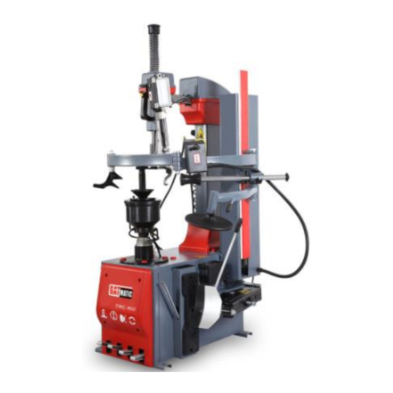
- Page 1 INSTALLATION, OPEATION, MAINTENANCE MANUAL KEEP THE MANUAL NEAR THE MACHINE ALL TIME AND MAKE SURE ALL USERS HAVE READ THIS TIRE CHANGER ITEM NO:TWC902...
-
Page 2: Table Of Contents
FOLLOW THE INSTRUCTIONS CAREFULLY TO GRANT THE MACHINE A CORRECT FUNCTION AND LONG SERVICE LIFE. TABLE OF CONTENT INTRODUCTION --------------------------------------------------------------------------- --- 3 Intended use-- ------------------------------------------------------------------------------------ 3 Technical data--------------------------------------------------------------------------------------- -4. TRANSPORTATION---------------------------------------------------------------------------------4 UNPACKING ------------------------------------------------------------------------------------------5 INSTALLATION ------------------------------------------------------------------------------ - 5 TRIAL OPERATION---------------------------------------------------------------------------------6 OPERATION --------------------------------------------------------------------------------------- 7 Breaking the bead ------------------------------------------------------------------------------- 7 Tire Demounting -------- ----------------------------------------------------------------------- 8... -
Page 3: Intended Use
Thank you for your purchase of this automatic tire changer. This guide has been made in order to supply the owner as well the user with the basic instructions for a correct use of the machine Read this guide carefully before using the machine and follow the instructions given by this guide carefully to grant the machine a correct function, efficiency and a long service life. -
Page 4: Transportation
External locking rim dimensions 10-20’’ Internal locking rim dimensions: 12- 24″ Max. tire diameter: 39’’(1000mm) Max. tire width 410mm/16’’ Table top rotation speed 7/Min Bead breaker Force (10bar) 2500kg/5500LBS Working pressure 8-10 bar Inflating pressure limiting device max. 3.5bar Relief valve on inflating device 4 bar Power supply voltage: 400v / 3phase... -
Page 5: Trial Operation
•The tire changer must be connected to the mains electric power supply and the compressed air system. It is therefore advisable to install the machine near these power sources. •The place of installation must also provide at least the space shown in pictures 4 to ensure all parts of the machine to operate correctly and without any restriction. - Page 6 Note: If the turntable turns in the opposite direction to that shown, reverse two of the wires in the three-phase plug. Make sure that you have known clearly the functions of every foot pedals and other important parts: Pressing the pedal (4) to tilt the arm; when the pedal is pressed again it returns to its normal position.
- Page 7 Attention:1. The minimum space between the machine and the wall is 0.5 meter. 2. Always keep the machine indoor and dry place. 2.1. Position the machine over a solid concrete pedestal, and fix it with anchor bolt. 2.2 Connect compressed air with 8mm air hose to the Air Filter inlet, keep it tight and adjust the air pressure to 0.6-1.0Mpa(6-10kg/cm), as shown in Fig.
-
Page 8: Operation
3.1 Mounting/demounting head and Assist Arm control system 3.1.1. Connect compressed air with 8mm air hose to the Air Filter inlet, keep it tight and adjust the air pressure to 0.6-1.0Mpa(6-10kg/cm). 3.1.2. Push the head lock button (12) to unlock the both vertical and horizontal bars for the mount head, and check the movements on both axis, get ready for operation. - Page 9 4.1 Before demounting a tire ● Deflate the tire ● Undo the valve spindle ● Remove all balance weights applied on the rim, if any. ● Open the bead breaker shovel and position the tire into the space between the shovel and the press pad, push the pedal 2 to break the bead, and repeat this step for other positions of the bead, as shown in the Fig.
- Page 10 Fig. 6 Fig.7 4.3.3 Push the pedal 1 to rotate the tire by 1 to 2 circles until the upper bead separate from the rim, lift up the assist arm control valve (17) to depress the press roller and release the locking nod and move the bar to the home position 4.4 Demount a tire 4.4.1 Push the pedal 4 to reset the mounting tool in the position.
- Page 11 4.4.7 Demounting lower bead. Move the tire holder 18 under the lower side of the tire, rotate the wheel and lift up the holder at the same time. Stop rotation as soon as the lower bead lifted up to upper edge of the rim, control the hook to lift the lower bead over the upper rim edge, rotate again the wheel until the complete tire is out of the rim(Fig.
-
Page 12: Inflating
INFLATING Pay utmost attention when inflating the tires. Keep strictly to the following instructions. A burst tire can cause serious injury or even death of the operator. • Check carefully that the wheel rim and the tire are of the same size. •... -
Page 13: Maintenance
MAINTENANCE GENERAL WARNINGS: Unauthorized personnel may not carry out maintenance work. •Regular maintenance as described in the instructions is essential for correct operation and long lifetime of the tire changer. •If maintenance is not carried out regularly, the operation and reliability of the machine may be compromised, thus placing the operator and anyone else in the vicinity at risk. -
Page 14: Trouble Shooting
TROUBLE SHOOTING Turntable rotates only in one direction Reverse broken Replace reverse Turntable does not rotate Belt broken Replace belt Reverse broken Replace reverse Check for loose wires in motor plug or the socket replace motor Turntable locks while removing /mounting tires Belt loose Adjust belt tension Clamps slow to open/close... - Page 15 ELECTRICAL & PNEUM. DIAGRAMS 115/230V-1PH 230V/400V-3PH...