Table of Contents
Advertisement
Quick Links
Advertisement
Table of Contents

Related Manuals for GATmatic GA-600S


Summary of Contents for GATmatic GA-600S
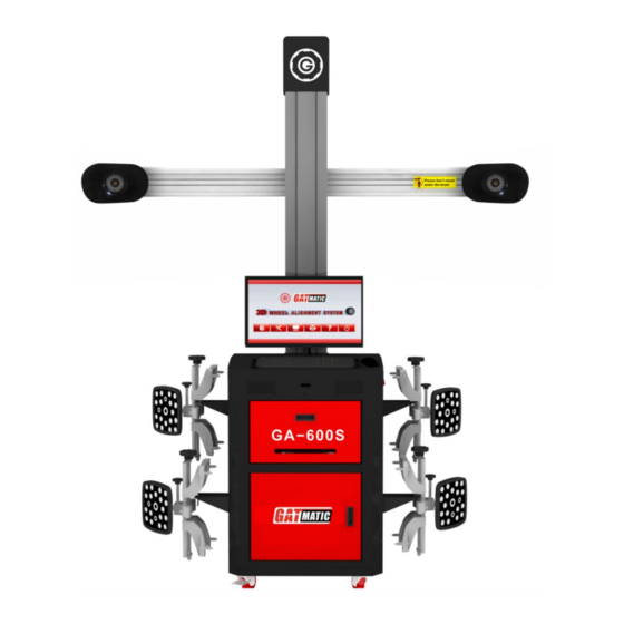
- Page 1 GA-600S 3D Wheel Aligner User Manual GA-600S 3D Wheel Aligner User Manual...
-
Page 2: Copyright Information
GA-600S 3D Wheel Aligner User Manual Copyright Information Copyright ©2009~2013. All rights reserved. No part of this publication may be reproduced, stored in a retrieval system, or transmitted in any form or by any means, electronic, mechanical, photocopying, recording or otherwise, without the prior written permission of our company. -
Page 3: General Safety Instructions
GA-600S 3D Wheel Aligner User Manual The targets are major components for wheel alignment, be careful in storage or operation. Clean the dirt with neutral detergent or ethanol. Accurate calibration is made during manufacturing, and the design doesn't require calibration work for a few years, install 3D series wheel aligner according to the user/installation manual. -
Page 4: Concrete Safety Instructions And Applied Symbols
GA-600S 3D Wheel Aligner User Manual Obligation by the operator to be considerate and avoid negligent acts: The equipment was designed and constructed with consideration to required harmonized standards, as well as additional technical specifications. It therefore corresponds with the current state of technology and provides the maximum standard in safety during the operation. - Page 5 GA-600S 3D Wheel Aligner User Manual Basic safety measures during normal operations: The machine may only be operated by trained and authorized personnel who know the operating instructions and capable of working with the equipment! Prior to switching the machine on, check and verify that: Only authorized personnel are located within the working range of the machine.
- Page 6 GA-600S 3D Wheel Aligner User Manual Observe environmental regulations: The legal regulations for waste prevention and proper recycling/disposal must be adhered to for all operations on and with the machine. Especially during installation, repair and maintenance operations, water-polluting materials, such as: Lubricants and oils - hydraulic oils - coolants.
-
Page 7: Table Of Contents
GA-600S 3D Wheel Aligner User Manual Table of Content Trademark Information ........................i Copyright Information ........................ii Precautions ............................ii General Safety Instructions ......................iii Concrete safety instructions and applied symbols .............. iv Chapter 1 Introduction ..........................1 1. 1 Definition ............................1 1. - Page 8 GA-600S 3D Wheel Aligner User Manual Chapter 4 Operation Instruction ......................1 4. 1 Preparation before test ......................1 4. 2 Software Operation ........................1 4. 2. 1 Alignment Measurement ...................2 4. 2. 2 System Management ....................8 4. 2. 3 General Setting ......................14 4.
-
Page 9: Chapter 1 Introduction
GA-600S 3D Wheel Aligner User Manual Chapter 1 Introduction 1.1 Definition 3D series wheel alignment system is to test wheel parameters and provide reference of manufacturer specs, by compare the two set of parameters, operator can adjust the vehicle wheel parameters to reasonable range, make the vehicle wheels in good condition and avoid unreasonable tire worn. -
Page 10: Camber
GA-600S 3D Wheel Aligner User Manual 1. 3. 1 Camber Camber is the leaning of the wheel inwards or outwards from the vertical. If the road wheel leans outwards from the vertical, it has positive camber and when leaning inwards from the vertical - negative camber, looking from the front or rear of the vehicle. -
Page 11: Steering Axle Inclination
GA-600S 3D Wheel Aligner User Manual 1. 3. 3 Steering Axle Inclination Steering Axle Inclination (SAI) is the angle of steering axis and vertical line (vehicle front view). As show in Figure 1.3. Correct Kingpin Inclination can equalize the loads applied on bearings so that the life of bearings can be prolonged and the controllability of steering is improved. -
Page 12: Toe-Out On Turn
GA-600S 3D Wheel Aligner User Manual 1. 3. 5 Toe-out on turn Toe-out on turns is defined as the difference of the steering angle between the two front wheels when turning left or right by 20°. see Figure 1.5.When the vehicle turns,... -
Page 13: Wheelbase Diff
GA-600S 3D Wheel Aligner User Manual 1. 3. 7 Wheelbase diff. Wheelbase difference is defined as the angle between the joint line of the centre of two rear wheels and that of the front wheels. It is positive when distance between the centre of the right wheels is large than that of left wheels;... -
Page 14: Delay (Angle)
GA-600S 3D Wheel Aligner User Manual 1. 3. 11 delay (angle) The same axle’s relative offset in longitudinal direction of the vehicle is called the delay. When the right wheel is behind of the left wheel on the same axle, the delay is positive, otherwise, it’s negative. -
Page 15: Tech Specs
GA-600S 3D Wheel Aligner User Manual 1.5 Tech Specs Power Supply: AC 110/220V 50/60 Hz Computer Host: Lenovo/Dell (or all in one computer) Monitor: 18. 5 inch color monitor (all in one computer comes with 23 inch monitor) Toe-in 0~+_20 degree. -
Page 16: Working Principle
GA-600S 3D Wheel Aligner User Manual 1. 7 Working Principle 3D series wheel aligner working principle is as show in figure 1. 9. The entire system can be divided into two categories: data acquisition and data processing. Figure 1. 9... -
Page 17: Chapter 2 Hardware Structure
GA-600S 3D Wheel Aligner User Manual Chapter 2 Hardware Structure 2. 1 Overall Structure 3D series wheel aligner mainly consist of column assembly, lateral beam assembly(include 2 sets of camera assembly), cabinet, computer host, monitor, printer, targets, clamps, communication cables, turntables, steering wheel holder, brake pedal... -
Page 18: Target And Clamps
GA-600S 3D Wheel Aligner User Manual 3D Series Wheel Aligner 2. 2 Target and Clamps 3D series wheel aligner has 4 targets (come together with 4 clamps), is a key component for acquire raw data of wheel alignment (Figure 2. 2), Cameras will capture target image for data processing. -
Page 19: Steering Wheel Holder
GA-600S 3D Wheel Aligner User Manual Figure 2. 3 2. 5 Steering wheel holder 3D series wheel aligner equipped with a steering wheel holder, as show in figure 2. 4. The steering wheel holder is mainly used when do rolling compensation. -
Page 20: Chapter 3 Basic Operation Procedure
GA-600S 3D Wheel Aligner User Manual Chapter 3 Basic Operation Procedure 3. 1 Precheck Ask the owner for vehicle drivability problems, symptoms, and wheel alignment history, and find out vehicle information such as make, model and year, etc. Check each chassis part carefully, include dust cover, bearing, rock arm, tripod-ball, shock absorber, tie rod ball and steering mechanism, for any loose or wear. -
Page 21: Chapter 4 Operation Instruction
GA-600S 3D Wheel Aligner User Manual Chapter 4 Operation Instruction 4. 1 Preparation before test 1) Ask the owner for vehicle drivability problems, symptoms, and wheel alignment history, and find out vehicle information such as make, model and year, etc. - Page 22 GA-600S 3D Wheel Aligner User Manual 4.2.1 Alignment Check Click [Alignment check] at main interface to start alignment procedure. 4.2.1.1 Select Vehicle Before alignment measurement, reference vehicle data shall be selected, as show below: Figure 4. 2 [Navigation Bar] Can access to independent measurement steps instead of follow the default sequence.
- Page 23 GA-600S 3D Wheel Aligner User Manual [Help Information] Help system and tips for the current page. [Target Monitor] Can find out the reason in target monitor screen when system prompt target blocked. Also can adjust the lateral beam height manually in this screen.
- Page 24 GA-600S 3D Wheel Aligner User Manual 4. Push the vehicle back and forward as instructed by the screen. Caution 1. Before push compensation, the steering wheel shall be well locked, otherwise, the wheel will not be stable when do push compensation, and this will cause inaccurate result of push compensation.
- Page 25 GA-600S 3D Wheel Aligner User Manual Can adjust the vehicle at this page, if caster swing is not considered important. when do adjustment, there might be requirement of lifting the vehicle up or lower the vehicle down, can operate the lift and the lateral beam will follow the lift movement to raise up or lower down.(this feature only applicable on auto focus model)
- Page 26 GA-600S 3D Wheel Aligner User Manual Figure 4. 6 Can adjust the vehicle at this page. when do adjustment, there might be requirement of lifting the vehicle up or lower the vehicle down, can operate the lift and the lateral beam will follow the lift movement to raise up or lower down.(this feature only...
-
Page 27: Print Report
GA-600S 3D Wheel Aligner User Manual Caution: 1. Before Caster Swing, be sure to mount the brake pedal depressor and remove the steering wheel holder. 2. At each measurement result page, the measurement result is displayed with different color. 1) Green: Value within standard range (OEM specs Min. ~Max. Range) 2) Bright orange: Value exceeded standard range (OEM specs Min. - Page 28 GA-600S 3D Wheel Aligner User Manual Figure 4. 8 [License No.]: License No. of the tested vehicle. [Client Name]: The related information of the vehicle owner. Client Information could be inputted directly with keyboard at this page. [Vehicle info.]: The related information of the current vehicle, including mileage, manufacturer, model, start year, end year.
- Page 29 GA-600S 3D Wheel Aligner User Manual 4. 2. 2. 1 Workshop information Workshop information mainly used to set workshop contact information and operator information. These information will be imported to the report for print out. For data management and track service record.
- Page 30 GA-600S 3D Wheel Aligner User Manual Figure 4. 11 [Quick index] At the bottom of the screen, quick index is provided. [Add Client]: Click [Add Client], and add client information by fill the form. Figure 4. 12 [Edit]: to modify/edit client information.
- Page 31 GA-600S 3D Wheel Aligner User Manual 4. 2. 2. 3 Language selection 3D series wheel aligner provide various language selections, the screen layout is as follows: Figure 4. 13 Operation instruction: Choose wanted language, and then click [OK]. The alignment system will restart with the selected language.
- Page 32 GA-600S 3D Wheel Aligner User Manual Figure 4. 14 [Quick index]: At the bottom of the screen, quick index is provided. [Add New]: To add vehicle data which not listed in the standard database, click this button, and add detailed specs on the prompted window. Inputted data will be stored in standard database after confirmation.
- Page 33 GA-600S 3D Wheel Aligner User Manual [Edit]: The edit/modify function only applicable for user defined data, while the OEM specs are fixed, can not be modified or delete. [Delete]: The edit/modify function only applicable for user defined data, while the OEM specs are fixed, can not be modified or delete.
- Page 34 GA-600S 3D Wheel Aligner User Manual [Exit]: Return to main interface. 4. 2. 3 General Settings At main interface to enter [General settings] page. In this page, some change could be made onto the software to suit operator’s need. Figure 4. 17 [Client List]: ALL client lists that did alignment measurement.
- Page 35 GA-600S 3D Wheel Aligner User Manual 4. 2. 4 Print Report At main interface, click [Report Print] to enter report page. In this page, operator could navigate or print clients’ service record. Figure 4. 18 [Client List]: ALL client lists that did alignment measurement.
-
Page 36: Help Information
GA-600S 3D Wheel Aligner User Manual 4. 2. 5 Help Information Help system could provide detailed operation instruction: Figure 4. 19 4. 2. 6. Exit Click to exit alignment software. 4-16... -
Page 37: Chapter 5 Frequent Asked Question
GA-600S 3D Wheel Aligner User Manual Chapter 5 Frequent asked question 5. 1 Computer Operation 5. 1. 1 Computer can not boot Check the power supply of computer. Check if the power button is clicked on both the computer host and monitor, ...