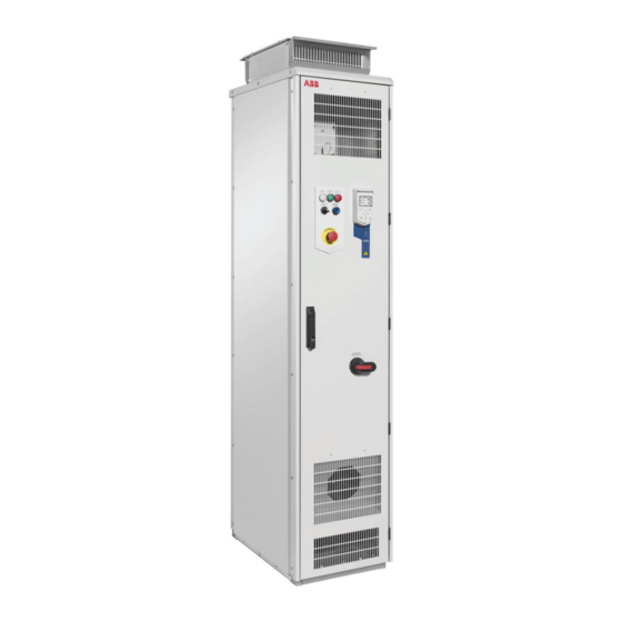
ABB ACQ580-07 Hardware Manual
Drives for water
Hide thumbs
Also See for ACQ580-07:
- User manual (36 pages) ,
- Electrical planning instructions (36 pages) ,
- User manual (40 pages)
Table of Contents
Advertisement
Quick Links
Advertisement
Table of Contents

Related Manuals for ABB ACQ580-07


Summary of Contents for ABB ACQ580-07
- Page 1 — ABB DRIVES FOR WATER ACQ580-07 Hardware manual...
- Page 3 ACQ580-07 Hardware manual Table of contents 1. Safety instructions 4. Mechanical installation 5. Guidelines for planning the electrical installation 6. Electrical installation 9. Start-up 3AXD50000045817 Rev E EFFECTIVE: 2020-09-22...
- Page 5 English ADDED: Connectivity for wired remote monitoring (option +K496) This option provides a gateway to connect the drive to ABB Ability™ via a local Ethernet network. Includes NETA-21 remote monitoring tool and FMBT-21 Modbus/TCP adapter module. The NETA and FMBT-21 are installed at the factory and wired internally. An Ethernet cable for customer connection is routed from the NETA to the external control connections mounting plate (number 6 in the layout drawing for frames R6...R9, number 12 for frames...
- Page 6 2 Update notice The NETA and FMBT-21 are installed at the factory and wired internally. An Ethernet cable for customer connection is routed from the NETA to the external control connections mounting plate (number 6 in the layout drawing for frames R6...R9, number 12 for frames R10 and R11).
- Page 7 Update notice 3 ■ Wiring of Pt100 relays External wiring of sensor modules is shown below. Contact load capacity 250 V AC 10 A. For the actual wiring, see the circuit diagram delivered with the drive. X506 1xPt100 Sensor 1 Internal wiring for overheat indication Sensor 1...3 overtemperature = contact open Sensor 2...
- Page 8 4 Update notice...
- Page 9 Table of contents 5 Table of contents 1 Safety instructions Contents of this chapter ..................Use of warnings and notes ................. General safety in installation, start-up and maintenance ........Electrical safety in installation, start-up and maintenance ........Electrical safety precautions ................ Additional instructions and notes ..............
-
Page 10: Table Of Contents
6 Table of contents Cabinet layout – R10 and R11 (top entry and exit of cables, options +H351 and +H353) ....................Mounting plate – R10 and R11 ..............Cooling air flow ..................... Door switches and lights ................Main switch-disconnector Q1 ............Control panel .................... - Page 11 Availability of du/dt filter and common mode filter by drive type ..Additional requirements for explosion-safe (EX) motors ....Additional requirements for ABB motors of types other than M2_, M3_, M4_, HX_ and AM_ ..............Additional requirements for ABB high-output and IP23 motors ..
- Page 12 8 Table of contents Signals that can be run in the same cable ........... Relay cable ....................Control panel to drive cable ................. PC tool cable ....................Routing the cables ....................General guidelines – IEC ................General guidelines – North America ............Continuous motor cable shield/conduit or enclosure for equipment on the motor cable ....................
-
Page 13: Table Of Contents
Table of contents 9 Connection diagram ..................Connection procedure (frames R6…R9) ............. Connection procedure (frames R6 and R7 with options +H351 and +H353) ......................Connection procedure (frames R8 and R9 with options +H351 and +H353) ......................Connection procedure (frames R10 and R11) ..........Connection procedure (frames R10 and R11 with options +H351 and +H353) ...................... - Page 14 10 Table of contents AI1 and AI2 as Pt100, Pt1000, Ni1000, KTY83 and KTY84 sensor inputs (X1) ......................Safe torque off (X4) ..................Technical data ..................... 8 Installation checklist Contents of this chapter ..................Checklist ......................9 Start-up Contents of this chapter ..................Start-up procedure ....................
- Page 15 Table of contents 11 Capacitors ......................Reforming the capacitors ................Fuses ........................Replacing AC fuses (frames R6 and R7) ............. Replacing AC fuses ..................Control panel ....................... Cleaning the control panel ................Replacing the battery ................... 12 Technical data Contents of this chapter ..................Ratings ........................
- Page 16 12 Table of contents Finish ......................Package ....................... Vertical package ................Horizontal package ................Package dimensions and weights for drives without empty cubicles (without options +C196 … +C201) ................... Package weights ..................Applicable standards ................... Markings ......................CE marking ......................Compliance with the European Low Voltage Directive ........
- Page 17 Description ......................Compliance with the European Machinery Directive ........Wiring ........................Connection principle ..................Single ACQ580-07 drive, internal power supply ....... Single ACQ580-07 drive, external power supply ......Wiring examples ................... Single ACQ580-07 drive, internal power supply ....... Single ACQ580-07 drive, external power supply ......
- Page 18 14 Table of contents Fault and warning messages ................Technical data ..................... Dimension drawing ..................... 16 CMOD-01 multifunction extension module (external 24 V AC/DC and digital I/O) Contents of this chapter ..................Product overview ....................Layout and example connections ............... Mechanical installation ..................
- Page 19 Table of contents 15 18 Disconnecting EMC filter and ground-to-phase varistor When to disconnect the ground-to-phase varistor: TN-S, IT, corner-grounded delta and midpoint-grounded delta systems ............Guidelines for installing the drive to a TT system ..........Identifying the grounding system of the electrical power network ...... Disconnecting the EMC filter and ground-to-phase varistor (frames R6…R9) ..
- Page 21 Safety instructions 17 Safety instructions Contents of this chapter This chapter contains the safety instructions which you must obey when you install, start up, operate and do maintenance work on the drive. If you ignore the safety instructions, injury, death or damage can occur. Use of warnings and notes Warnings tell you about conditions which can cause injury or death, or damage to the equipment.
- Page 22 18 Safety instructions General safety in installation, start-up and maintenance These instructions are for all personnel who do work on the drive. WARNING! Obey these instructions. If you ignore them, injury or death, or damage to the equipment can occur. •...
- Page 23 Safety instructions 19 It is heavy and its center of gravity is high. The module overturns from a sideways tilt of 5 degrees. Do not leave the module unattended on a sloping floor. • To prevent the drive module from falling, attach its top lifting lugs with chains to the cabinet (1) before you push the module into the cabinet and pull it from the cabinet.
- Page 24 20 Safety instructions • Before you activate the automatic fault reset or automatic restart functions of the drive control program, make sure that no dangerous situations can occur. These functions reset the drive automatically and continue operation after a fault or supply break.
- Page 25 Safety instructions 21 • Open the charging switch if present. • Open the disconnector of the supply transformer. (The main disconnecting device in the drive cabinet does not disconnect the voltage from the AC input power busbars of the drive cabinet.) •...
- Page 26 22 Safety instructions Measuring points of frames R6 to R9 are shown below. L1, L2, L3...
- Page 27 Safety instructions 23 Measuring points of frames R10 and R11 are shown below. You can also remove the metallic shield and measure through the holes in the clear plastic shroud behind it. L1 L2 • Make sure that the voltage between the drive output terminals (T1/U, T2/V, T3/W) and the grounding (PE) busbar is zero.
- Page 28 There are electromagnetic fields present which can interfere with the function of such devices. This can cause a health hazard. • ABB recommends against attaching the cabinet by arc welding. If you have to, obey the welding instructions in the drive manuals. Note: •...
- Page 29 Safety instructions 25 ■ Grounding These instructions are for all personnel who are responsible for the grounding of the drive. WARNING! Obey these instructions. If you ignore them, injury or death, or equipment malfunction can occur, and electromagnetic interference can increase. If you are not a qualified electrical professional, do not do grounding work.
- Page 30 26 Safety instructions General safety in operation These instructions are for all personnel that operate the drive. WARNING! Obey these instructions. If you ignore them, injury or death, or damage to the equipment can occur. • Keep the cabinet doors closed when the drive is powered. With the doors open, a risk of a potentially fatal electric shock, arc flash or high-energy arc blast exists.
- Page 31 Safety instructions 27 If you are not a qualified electrical professional, do not do installation or maintenance work. • Do not do work on the drive when a rotating permanent magnet motor is connected to it. A rotating permanent magnet motor energizes the drive including its input and output power terminals.
- Page 33 Introduction to the manual 29 Introduction to the manual Contents of this chapter This chapter describes the intended audience and contents of the manual. It contains a flowchart of steps in examining the delivery, installing and commissioning the drive. The flowchart refers to chapters/sections in this manual and other manuals. Target audience This manual is intended for people who plan the installation, install, start up and do maintenance work on the drive, or create instructions for the end user of the drive...
- Page 34 30 Introduction to the manual Quick installation flowchart Task Plan the electrical installation and acquire the accessories needed Guidelines for planning the (cables, fuses, etc.). electrical installa- Check the ratings, required cooling air flow, input power connection, tion (page 79) compatibility of the motor, motor connection, and other technical Technical data (page 197) data.
- Page 35 Introduction to the manual 31 Task Operate the drive: start, stop, speed control etc. Start-up (page 155) firmware manual Terms and abbreviations Term/ Description Abbrevi- ation ACH-AP-H Assistant control panel with Hand-Off-Auto functionality ACH-AP-W Assistant control panel with Hand-Off-Auto functionality and Bluetooth interface CCU-24 Type of control unit CHDI-01...
- Page 36 Code (Eng- Code (Transla- lish/Multilingual) tion) Drive hardware manuals and guides Drive/converter/inverter safety instructions 3AXD50000037978 ACQ580-07 drives (75 to 500 kW) hardware manual 3AXD50000045817 Converter module lifting device for drive cabinets hardware 3AXD50000210268 manual ACX-AP-x Assistant control panels user’s manual 3AUA0000085685...
- Page 37 Introduction to the manual 33 You can find manuals and other product documents in PDF format on the Internet at www.abb.com/drives/documents. The code below opens an online listing of the manuals applicable to this product. ACQ580-07 manuals...
- Page 39 Operation principle and hardware description 35 Operation principle and hardware description Contents of this chapter This chapter briefly describes the operation principle and construction of the drive.
- Page 40 36 Operation principle and hardware description Product overview The ACQ580-07 is a drive module for controlling AC induction motors, synchronous reluctance motors and synchronous permanent magnet motors in open loop control. The single-line circuit of the drive is shown below.
- Page 41 Operation principle and hardware description 37 Layout ■ General information on the cabinet layout „ „ IP21 IP42 UL Type 1 UL Type 1 Filtered (option +B054)
- Page 42 38 Operation principle and hardware description ■ Cabinet layout – R6 and R7 (bottom entry and exit of cables) The cabinet layout of frame R7 with du/dt filter (option +E205) is shown below. Degree of protection IP42 (UL Type 1 Filtered [option +B054]). Frame R6 looks similar. Cabinet door closed Auxiliary voltage transformer T21 Cabinet door open...
- Page 43 Operation principle and hardware description 39 Power and control cable entries ■ Cabinet layout – R6 and R7 (top entry and exit of cables, options +H351 and +H53) Cabinet door closed Power and control cable entries Cabinet door open Auxiliary voltage transformer T21 Cabinet door open and motor cable cubicle Motor cable connection terminals cover removed...
- Page 44 40 Operation principle and hardware description Lifting lugs Common mode filter (option +E208) behind the mounting plate Cabinet door fan du/dt filter (option +E205) ■ Cabinet layout – R8 and R9 (bottom entry and exit of cables) The cabinet layout of frame R9 with du/dt filter (option +E205) is shown below. Degree of protection IP42 (UL Type 1 Filtered [option +B054]).
- Page 45 Operation principle and hardware description 41 Gratings for cooling air out Additional I/O terminal block (option +L504) Drive control unit Mounting plate, see section Mounting plate – R6 to R9 (page 42) Lifting lugs Common mode filter (option +E208) Cabinet door fan du/dt filter (option +E205) Power and control cable entries Motor cable connection terminals...
- Page 46 42 Operation principle and hardware description Drive control panel AC fuses Operating switch Main contactor (Q2, option +F250) Main switch handle Power cable connection terminals of the drive module behind the shroud Gratings for cooling air in Drive module Gratings for cooling air out Additional I/O terminal block (option +L504) Drive control unit Mounting plate, see section...
- Page 47 Operation principle and hardware description 43 +G300 switch-disconnector and miniature cir- External main contactor control cuit breaker for cabinet heater (option +G300) Emergency stop relay for options X250 Indication of main contactor status5 +Q951 and +Q963 Q95, Switch-disconnector and miniature X289 Indication of the status of the molded circuit breaker for cabinet heater (op-...
- Page 48 44 Operation principle and hardware description T22, 24VDC power supply and buffer with X969 Connection of external Safe torque off emergency stop options (+Q951 and button +Q963), also with line contactor option (+F250). X251, X4, X6, X56, X53, X51, X55, X18 and X19: for internal use. X250 Terminals for X250...
- Page 49 Operation principle and hardware description 45 ■ Cabinet layout – R10 and R11 (bottom entry and exit of cables) Cabinet door closed Main switch-disconnector Cabinet door open AC fuses Gratings for cooling air out Line contactor (option +F250) Operating switch Lifting lugs Drive control panel Drive control unit...
- Page 50 46 Operation principle and hardware description Cabinet door open, mounting plates and Input cable connection terminals cabinet shrouds removed Power and control cable entries Drive module Motor cable connection terminals Auxiliary voltage transformer T21...
-
Page 51: Cabinet Layout - R10 And R11 (Top Entry And Exit Of Cables, Options +H351 And +H353)
Operation principle and hardware description 47 ■ Cabinet layout – R10 and R11 (top entry and exit of cables, options +H351 and +H353) Cabinet door closed Lifting lugs Cabinet door open Cubicle for motor cabling Gratings for cooling air out Drive control unit Drive control panel Mounting plate, see section... -
Page 52: Mounting Plate - R10 And R11
48 Operation principle and hardware description Cabinet door open, lower shrouds and Auriliary voltage transformer T21 motor cable cubicle cover removed Input cable connection terminals behind Drive module the shroud Motor cable connection terminals ■ Mounting plate – R10 and R11 The components and terminals on the mounting plate of frames R10 and R11 are shown below. - Page 53 Operation principle and hardware description 49 Drive control unit X289 Indication of the status of the molded case circuit breaker (option +F289) Emergency stop relay for options X300 Connection terminals for cabinet +Q951 and +Q963 heater (option +G300) Q95, Switch-disconnector and miniature X951 Connection of external emergency circuit breaker for cabinet heater (op-...
-
Page 54: Cooling Air Flow
50 Operation principle and hardware description T22, 24VDC power supply and buffer with K41.1 Ready pilot light control relay (option emergency stop options (+Q951 and +G327) +Q963), also with line contactor option (+F250). External main contactor control K41.2 Run pilot light control relay (op- tion+G328) X250 Indication of main contactor status... -
Page 55: Door Switches And Lights
Operation principle and hardware description 51 ■ Door switches and lights Label in English Label in local Description language READY Ready pilot light (option +G327) Run pilot light (option+G328) FAULT Fault pilot light (option +G329) MAIN CONTACT- Operating switch with option +F250 Opens the main contactor (Q2) and disables OFF ON starting of the drive... -
Page 56: Control By Pc Tools
52 Operation principle and hardware description Control by PC tools There is a USB connector on the front of the panel that can be used to connect a PC to the drive. When a PC is connected to the control panel, the control panel keypad is disabled. -
Page 57: Overview Of Power And Control Connections
Operation principle and hardware description 53 „ Overview of power and control connections The diagram shows the power connections and control interfaces of the drive. SLOT 1 SLOT 2 M 3 ~ Option slot 1 for optional fieldbus adapter modules Option slot 2 for optional I/O extension modules Embedded fieldbus connector Panel port... -
Page 58: Descriptions Of Options
54 Operation principle and hardware description Descriptions of options Note: All options are not available for all drive types, do not coexist with certain other options, or may require additional engineering. Check actual availability with ABB. ■ Degree of protection... -
Page 59: Plinth Height (Options +C164 And +C179)
Operation principle and hardware description 55 • all components UL/CSA Listed/Recognized • maximum supply voltage 480 V • US-type main switch and fuses. ■ Plinth height (options +C164 and +C179) The standard height of the cabinet plinth is 50 mm. These options specify a plinth height of 100 mm (+C164) or 200 mm (+C179). -
Page 60: Cabinet Heater With External Supply (Option +G300)
56 Operation principle and hardware description For North American market only. ■ Cabinet heater with external supply (option +G300) The option contains: • heating elements in the cubicles or supply/inverter modules • load switch for providing electrical isolation during service •... -
Page 61: Additional Terminal Block X504 (Option +L504)
Operation principle and hardware description 57 ■ Additional terminal block X504 (option +L504) The standard terminal blocks of the drive control unit are wired to the additional terminal block at the factory for customer control wiring. The terminals are spring loaded. Note: The optional modules inserted in the slots of the control unit are not wired to the additional terminal block. -
Page 62: Type Designation Label
Type designation key The type designation contains information on the specifications and configuration of the drive. The first digits from left express the basic configuration (eg, ACQ580-07-0640A-4). The optional selections are given thereafter, separated by plus signs, eg, +B055. The main selections are described below. -
Page 63: Option Codes
Operation principle and hardware description 59 Code Description When no options are selected: cabinet-installed drive, IP21, main switch, AC fuses, ACH-AP-H assistant control panel, for frames R6 to R9 EMC filtering for first environment TN grounded systems (category C2), for frames R10 and R11 EMC filtering for second environment TN grounded systems (category C3), input choke, common mode filter in frames R10 and R11, coated boards, ACQ580 pump control program, EIA/RS-485 fieldbus connector, Safe torque off function, bottom entry and exit of cables, multilingual... - Page 64 60 Operation principle and hardware description Code Description E208 Common mode filtering (standard with frames R10 and R11) F250 Main (line) contactor F289 MCCB circuit breaker Cabinet and module heating elements (external supply). See section Cabinet heater G300 with external supply (option +G300) (page 56).
- Page 65 Operation principle and hardware description 61 Code Description M602 Trip limit setting range: 2.5 … 4 A M603 Trip limit setting range: 4 … 6.3 A M604 Trip limit setting range: 6.3 … 10 A M605 Trip limit setting range: 10…16 A P912 Seaworthy packaging P929...
-
Page 67: Mechanical Installation
Mechanical installation 63 Mechanical installation Contents of this chapter This chapter describes the mechanical installation procedure of the drive. Examining the installation site Examine the installation site. Make sure that: • The installation site is sufficiently ventilated or cooled to remove heat from the drive. See the technical data. -
Page 68: Necessary Tools
64 Mechanical installation Do not install the drive on an elevated platform or a recess. The module extraction/installation ramp included with the drive is only suitable for a height difference of 50 mm (2 in) maximum (ie. the standard plinth height of the drive). Necessary tools The tools required for moving the unit to its final position, fastening it to the floor and wall and tightening the connections are listed below:... - Page 69 Mechanical installation 65...
- Page 70 66 Mechanical installation Vertical package (frames R10 and R11): 1088 Lifting the transport package with slings. Lifting points Lifting the transport package with forklift...
-
Page 71: Unpacking The Transport Package
Mechanical installation 67 ■ „ Unpacking the transport package This drawing shows the layout of the horizontal transport package. Bracket for attaching the drive to the Timber wooden pallet Cardboard packing hood Drive cabinet Wooden pallet Plinth (delivered in a separate package for frames R6…R9) Straps Unpack the horizontal transport package as follows:... -
Page 72: Examining The Delivery
68 Mechanical installation 4. Remove the plastic wrapping. ■ Examining the delivery The drive delivery contains: • drive cabinet line-up • optional modules (if ordered) installed onto the control unit(s) at the factory • appropriate drive and optional module manuals •... - Page 73 „ Mechanical installation 69 „...
-
Page 74: Lifting Lugs
Lift the cabinet to its position. Maximum allowed angle of the lifting slings is 20° (10° for „ frames R10 and R11, IP54). ° Max. 10 ° Max. 20 R10, R11 IP54 „ Lifting lugs Certificate of conformity The certificate is available in ABB Library at www.abb.com/drives/documents (document number 3AXD10001061361). - Page 75 Mechanical installation 71 Declaration of Conformity...
-
Page 76: Moving The Cabinet After Unpacking
72 Mechanical installation ■ Moving the cabinet after unpacking Move drive cabinet carefully in the upright position. Avoid tilting. The center of gravity of the cabinet is high. -
Page 77: Moving The Cabinet With Rollers
Mechanical installation 73 Moving the cabinet with rollers Lay the cabinet on the rollers and move it care- fully until close to its final location. Remove the rollers by lifting the unit with a crane, forklift, pallet truck or jack. Moving the cabinet to its final placement with a slate bar Move the cabinet into its final position with an iron bar. -
Page 78: Attaching The Cabinet (Non-Marine Units)
74 Mechanical installation > 400 mm (15.75”) 120° Note 1: Any height adjustment must be done before attaching the cabinet sections to the floor or to each other. Height adjustment can be done by using metal shims between the cabinet bottom and floor. Note 2: Depending on the size of the cabinet, it has either bolt-on lifting eyes, or lifting bars with lifting holes. - Page 79 Mechanical installation 75 2. If floor mounting at the back is not possible, fasten the top of the cabinet to the wall with L-brackets (not included in the delivery) bolted to the lifting eye/bar holes, and suitable hardware. Clamping bottom to floor Attaching top to wall...
-
Page 80: Alternative 2 - Using The Holes Inside The Cabinet
76 Mechanical installation Alternative 2 – Using the holes inside the cabinet 1. Attach the cabinet to the floor through the bottom fastening holes with M10 to M12 (3/8” to 1/2”) bolts. The recommended maximum distance between the front edge fastening points is 800 mm (31.5”). -
Page 81: Alternative 3 - Cabinets With Plinth Options +C164 And +C179
Mechanical installation 77 Alternative 3 – Cabinets with plinth options +C164 and +C179 Frames R6…R9 1. Attach the plinth to the floor with the brackets included in the plinth package. 2. Lift the cabinet onto the plinth and attach it to the plinth with the L-brackets delivered with the plinth. -
Page 82: Miscellaneous
■ Arc welding ABB does not recommend attaching the cabinet by arc welding. However, if arc welding is the only option, connect the return conductor of the welding equipment to the cabinet frame at the bottom within 0.5 meters (1’6”) of the welding point. -
Page 83: Guidelines For Planning The Electrical Installation
ABB does not assume any liability whatsoever for any installation which breaches the local laws and/or other regulations. Furthermore, if the recommendations given by ABB are not followed, the drive may experience problems that the warranty does not cover. -
Page 84: Examining The Compatibility Of The Motor And Drive
Examining the compatibility of the motor and drive Use asynchronous AC induction motors, permanent magnet synchronous motors, AC induction servomotors or ABB synchronous reluctance motors (SynRM motors) with the drive. Select the motor size and drive type from the rating table on basis of the AC line voltage and motor load. - Page 85 Guidelines for planning the electrical installation 81 This table shows the requirements when an ABB motor is in use. Motor type Nominal AC sup- Requirement for ply voltage Motor insu- ABB du/dt and common mode filters, in- lation sys- sulated N-end motor bearings P n <...
- Page 86 82 Guidelines for planning the electrical installation This table shows the requirements when a non-ABB motor is in use. Motor type Nominal AC sup- Requirement for ply voltage Motor insu- ABB du/dt and common mode filters, in- lation sys- sulated N-end motor bearings P n <...
-
Page 87: Availability Of Du/Dt Filter And Common Mode Filter By Drive Type
If you will use an explosion-safe (EX) motor, follow the rules in the requirements table above. In addition, consult the motor manufacturer for any further requirements. Additional requirements for ABB motors of types other than M2_, M3_, M4_, HX_ and AM_ Use the selection criteria given for non-ABB motors. -
Page 88: Additional Requirements For Non-Abb High-Output And Ip23 Motors
The rated output power of high-output motors is higher than what is stated for the particular frame size in EN 50347 (2001). If you plan to use a non-ABB high-output motor or an IP23 motor, consider these additional requirements for protecting the motor insulation and bearings in drive systems: •... -
Page 89: Additional Data For Calculating The Rise Time And The Peak Line-To-Line Voltage
Guidelines for planning the electrical installation 85 Nominal AC supply Requirement for voltage Motor insulation sys- ABB du/dt and common mode filters, insu- lated N-end motor bearings P n < 100 kW or frame 100 kW < P n < 350 kW size < IEC 315 IEC 315 <... - Page 90 86 Guidelines for planning the electrical installation Û du/dt ------------ - (1/Ps) l (m) du/dt ------------ - (1/Ps) Û l (m) Drive with du/dt filter Drive without du/dt filter Motor cable length Û LL /U N Relative peak line-to-line voltage (du/dt)/U N Relative du/dt value...
-
Page 91: Selecting The Power Cables
Guidelines for planning the electrical installation 87 Selecting the power cables ■ General guidelines Select the input power and motor cables according to local regulations. • Current: Select a cable capable of carrying the maximum load current. • Temperature: For an IEC installation, select a cable rated for at least 70 °C (158 °F) maximum permissible temperature of conductor in continuous use. -
Page 92: Typical Power Cable Sizes
88 Guidelines for planning the electrical installation • use a second protective earth conductor of the same cross-sectional area as the original protective earth conductor, • use a device that automatically disconnects the supply if the protective earth conductor is damaged. If the protective earth conductor is separate (that is, it does not form part of the input power cable or the input power cable enclosure), the minimum cross-sectional area must be: 2.5 mm 2 when the conductor is mechanically protected,... -
Page 93: Alternate Power Cable Types
Guidelines for planning the electrical installation 89 Alternate power cable types Cable type Use as input power cabling Use as motor cabling Yes with phase conductor Yes with phase conductor smaller than 10 mm 2 (8 AWG) smaller than 10 mm 2 (8 AWG) Cu, or motors up to 30 kW (40 hp). -
Page 94: Not Allowed Power Cable Types
■ Additional guidelines, North America ABB recommends the use of conduit for power wiring to the drive and between the drive and the motor(s). Due to the variety of application needs, metallic and non-metallic conduit can be used. ABB recommends the use of metallic conduit. -
Page 95: Metal Conduit
Guidelines for planning the electrical installation 91 Wiring method Notes Free air Prefer symmetrical shielded VFD cable. Enclosures, air handlers, etc. Allowed internally in enclosures when in accord- ance with UL. 1) Metallic conduit may be used as an additional ground path, provided this path is a solid path capable of handling ground currents. -
Page 96: Selecting The Control Cables
■ Relay cable The cable type with braided metallic shield (for example ÖLFLEX by LAPPKABEL, Germany) has been tested and approved by ABB. ■ Control panel to drive cable Use EIA-485 with male RJ-45 connector, cable type Cat 5e or better. The maximum permitted length of the cable is 100 m (328 ft). -
Page 97: Routing The Cables
Guidelines for planning the electrical installation 93 Routing the cables ■ General guidelines – IEC • Route the motor cable away from other cables. Motor cables of several drives can be run in parallel installed next to each other. • Install the motor cable, input power cable and control cables on separate trays. -
Page 98: General Guidelines - North America
94 Guidelines for planning the electrical installation ■ General guidelines – North America Make sure that the installation is in accordance with national and local codes. Obey these general guidelines: • Use separate conduits for the input power, motor, brake resistor (optional), and control cabling. -
Page 99: Continuous Motor Cable Shield/Conduit Or Enclosure For Equipment On The Motor Cable
Guidelines for planning the electrical installation 95 ■ Continuous motor cable shield/conduit or enclosure for equipment on the motor cable To minimize the emission level when safety switches, contactors, connection boxes or similar equipment are installed on the motor cable between the drive and the motor: •... -
Page 100: Protecting The Motor And Motor Cable In Short-Circuits
96 Guidelines for planning the electrical installation R6, R7 R8…R11 ■ Protecting the motor and motor cable in short-circuits The drive protects the motor cable and motor in a short-circuit situation when the motor cable is sized according to the nominal current of the drive. No additional protection devices are needed. -
Page 101: Protecting The Drive Against Ground Faults
(English) +Q951 Emergency stop, stop category 0 (option +Q951) for ACS580-07, 3AXD50000171828 ACH580-07 and ACQ580-07 drives user's manual +Q963 Emergency Stop, Category 0 (option +Q963) without opening main 3AXD50000171835 contactor with safety relay for ACS580-07, ACH580-07 and ACQ580-07 drives user's manual... -
Page 102: Using Power Factor Compensation Capacitors With The Drive
98 Guidelines for planning the electrical installation It keeps the contactor closed in short power-loss situations. If the drive is equipped an external uninterruptible auxiliary power supply (option +G307), it keeps the main contactor closed in power-loss situations. Note that if the power loss lasts so long that the drive trips on undervoltage, a fault reset and a fresh start command is required to continue operation. -
Page 103: Using A Safety Switch Between The Drive And The Motor
Guidelines for planning the electrical installation 99 Using a safety switch between the drive and the motor ABB recommends to install a safety switch between the permanent magnet motor and the drive output. The switch is needed to isolate the motor from the drive during maintenance work on the drive. -
Page 104: Implementing A Bypass Connection
IEC/EN 61800-5-1, subclause 6.5.3, for example, “THIS MACHINE STARTS AUTOMATICALLY”. Bypass connection is available as a factory-installed option for some cabinet-installed drive types. Consult ABB for more information. WARNING! Never connect the drive output to the electrical power network. The connection may damage the drive. -
Page 105: Implementing A Motor Temperature Sensor Connection
Guidelines for planning the electrical installation 101 230 V AC 230 V AC + 24 V DC Relay output Varistor RC filter Diode Implementing a motor temperature sensor connection WARNING! IEC 60664 and IEC 61800-5-1 require double or reinforced insulation between live parts and accessible parts when: •... -
Page 106: Connecting Motor Temperature Sensor To The Drive Via An Option Module
102 Guidelines for planning the electrical installation Note: Extra-low voltage circuits (for example, 24 V DC) typically do not meet these requirements. As an alternative, you can connect the sensor with basic insulation to the analog/digital input(s) of the drive, if you do not connect any other external control circuits to the drive digital and analog inputs. -
Page 107: Supplying Power For The Auxiliary Circuits
Guidelines for planning the electrical installation 103 Option module Temperature Temperature sensor in- sensor type sulation requirement Type Insulation/Isolation Pt100, Pt1000 CMOD-02 Reinforced insulation No special requirement between the sensor con- CPTC-02 No special requirement nector and the other con- nectors of the module (in- cluding drive control unit connector). -
Page 109: Electrical Installation
Electrical installation 105 Electrical installation Contents of this chapter This chapter gives instructions on the wiring the drive. Warning WARNING! If you are not a qualified electrical professional, do not do installation or maintenance work. Obey the safety instructions of the drive. If you ignore them, injury or death, or damage to the equipment can occur. -
Page 110: Layout Of The Cable Entries (Frames R6
106 Electrical installation Layout of the cable entries (frames R6…R9) The layout of the input and motor cable connection terminals of frame R9 bottom entry without du/dt filter option (+E205) is shown below. The shrouds in front of the terminals are removed. -
Page 111: Layout Of The Cable Entries (Frames R10 And R11)
Electrical installation 107 Layout of the cable entries (frames R10 and R11) The layout of the input and motor cable connection terminals of frame R10 bottom entry is shown below. The shrouds in front of the terminals are removed. The layout is similar for frame R11. -
Page 112: Measuring The Insulation
Use a measuring voltage of 1000 V DC. The insulation resistance of an ABB motor must be more than 100 Mohm (reference value at 25 C [77°F]). For the insulation resistance of other motors, refer to the manufacturer’s instructions. -
Page 113: Grounding System Compatibility Check
Electrical installation 109 U1-PE, V1-PE, W1-PE 1000 V DC, > 100 Mohm Grounding system compatibility check The standard drive can be installed to a symmetrically grounded TN-S system. If you install the drive to another system, you may need to disconnect the EMC filter and ground-to-phase varistor. - Page 114 110 Electrical installation 2. Prepare the ends of the cables. WARNING! Apply grease to stripped aluminum conductors before attaching them to non-coated aluminum cable lugs. Obey the grease manufacturer’s instructions. Aluminum-aluminum contact can cause oxidation in the contact surfaces. 3. If fire insulation is used, make an opening in the mineral wool sheet according to the diameter of the cable.
-
Page 115: Connection Diagram
Electrical installation 111 ■ Connection diagram „ T1/ T2/ T3/ (PE) (PE) Use a separate grounding PE cable (1a) or a cable with a separate PE conductor (1b) if the conductivity of the shield does not meet the requirements for the PE conductor. 360-degree grounding is recommended if shielded cable is used. - Page 116 112 Electrical installation 360-degree grounding is required. Line contactor (option +F250) Common mode filter (option +E208 for frames R6 to R9). Standard in frames R10 and R11. du/dt filter (option +E205) Use a separate grounding cable if the shield does not meet the requirements of IEC 61439- 1 and there is no symmetrically constructed grounding conductor in the cable.
-
Page 117: Connection Procedure (Frames R6
Electrical installation 113 ■ Connection procedure (frames R6…R9) This section applies to drives with bottom entry and exit of power cables. 1. Do the steps in section Electrical safety precautions (page 20) before you start the work. 2. Open the cabinet door. 3. -
Page 118: Connection Procedure (Frames R6 And R7 With Options +H351 And +H353)
114 Electrical installation 5. For drives without option +E205: Knock out holes in the shroud for the motor cable conductors. 6. Connect the twisted shields of the motor cables to the ground bar and the phase conductors to the U2, V2 and W2 terminals of the drive module. For drives with du/dt filter (option +E205), connect the phase conductors to the T1/U2, T2/V2 and T3/W2 terminals of the cabinet with cable lugs. - Page 119 Electrical installation 115 4. Connect the twisted shields of the motor cables to the ground bar and the phase conductors to the U2, V2 and W2 terminals of the drive module. 5. Connect the twisted shields of the input cables and separate ground cable (if present) to the PE terminal of the cabinet and the phase conductors to the L1, L2 and L3 terminals.
-
Page 120: H353)
116 Electrical installation 6. Tighten the power cable screws to the torque given in Terminal and entry data for the power cables (page 209). 7. Reinstall the shrouds and mounting plate. ■ Connection procedure (frames R8 and R9 with options +H351 and +H353) 1. - Page 121 Electrical installation 117 3. Remove the shrouds. 4. Connect the twisted shields of the motor cables to the ground bar and the phase conductors to the U2, V2 and W2 terminals of the drive module. 5. Connect the twisted shields of the input cables and separate ground cable (if present) to the PE terminal of the cabinet and the phase conductors to the L1, L2 and L3 terminals.
-
Page 122: Tighten The Power Cable Screws To The Torque Given In Terminal And Entry Data For The Power Cables
118 Electrical installation 6. Tighten the power cable screws to the torque given in Terminal and entry data for the power cables (page 209). 7. Reinstall the shrouds and mounting plate. -
Page 123: Connection Procedure (Frames R10 And R11)
Electrical installation 119 ■ Connection procedure (frames R10 and R11) 1. Do the steps in section Electrical safety precautions (page 20) before you start the work. 2. Open the cabinet door. 3. Remove the shroud. 4. Remove the door fan mounting plate. See section Replacing the door fan (frames R10 and R11) (page 166) 5. -
Page 124: H353)
120 Electrical installation 7. Tighten the power cable screws to the torque given in Terminal and entry data for the power cables (page 209). 8. Reinstall the shrouds and mounting plate. ■ Connection procedure (frames R10 and R11 with options +H351 and +H353) 1. -
Page 125: Remove The Door Fan Mounting Plate. See Section
Electrical installation 121 3. With top entry (option +H351) and bottom exit: Undo the mounting screws and pull the shroud out. Remove the door fan mounting plate. See section Replacing the door fan (frames R10 and R11) (page 166) 4. With top entry and top exit (options +H351 and +H353): Remove the shrouds and door fan (see Replacing the door fan (frames R10 and R11) (page 166)). -
Page 126: Connect The Twisted Shields Of The Motor Cables To The Ground Bar And The Phase Conductors To The U2, V2 And W2 Terminals Of The Drive Module
122 Electrical installation 5. Connect the twisted shields of the motor cables to the ground bar and the phase conductors to the U2, V2 and W2 terminals of the drive module. 6. Connect the twisted shields of the input cables and separate ground cable (if present) to the PE terminal of the cabinet and the phase conductors to the L1, L2 and L3 terminals. -
Page 127: Connecting The Control Cables
Electrical installation 123 7. Tighten the power cable screws to the torque given in Terminal and entry data for the power cables (page 209). 8. Reinstall the shrouds and mounting plate. Connecting the control cables See chapter Control unit (page 139) for the default I/O connections of the drive control program. -
Page 128: Overview Of Control Cable Connection Procedure
124 Electrical installation ■ Overview of control cable connection procedure WARNING! Obey the instructions in chapter Safety instructions. If you ignore them, injury or death, or damage to the equipment can occur. 1. Stop the drive and do the steps in section Electrical safety precautions (page 20) before you start the work. - Page 129 Electrical installation 125 Note 1: Keep the shields continuous as close to the connection terminals as possible. Secure the cables mechanically at the entry strain relief. Note 2: If the outer surface of the shield is non-conductive: • Cut the shield at the midpoint of the bare part. Be careful not to cut the conductors or the grounding wire (if present).
- Page 130 126 Electrical installation Stripped cable Conductive surface of the shield exposed Stripped part covered with copper foil Cable shield Copper foil Shielded twisted pair Grounding wire Note for top entry of cables: When each cable has its own rubber grommet, sufficient IP and EMC protection can be achieved.
- Page 131 Electrical installation 127 6. If more than one cable go through a grommet, seal the grommet by applying Loctite 5221 inside the grommet.
-
Page 132: Routing The Control Cables Inside The Cabinet
128 Electrical installation ■ Routing the control cables inside the cabinet The route of the control cables is shown below in frame R9. The route is similar for frames R6, R7 and R8. X504 (+L504) - Page 133 Electrical installation 129...
- Page 134 130 Electrical installation The route of the control cables for frames R10 and R11 is shown below. X504 (+L504)
-
Page 135: Connecting External Wiring To The Control Unit Or Optional I/O Terminal Block
Electrical installation 131 ■ Connecting external wiring to the control unit or optional I/O terminal block Note: Keep any signal wire pairs twisted as close to the terminals as possible. Twisting the wire with its return wire reduces disturbances caused by inductive coupling. Note: Leave slack to the control wires to make it possible to lift the control unit mounting plate a little when the drive module is replaced. -
Page 136: Connecting The Emergency Stop Push Buttons (Options +Q951 And +Q963)
132 Electrical installation Leave the other ends of the control cable shields unconnected or ground them indirectly via a high-frequency capacitor with a few nanofarads, eg, 3.3 nF / 630 V. The shield can also be grounded directly at both ends if they are in the same ground line with no significant voltage drop between the end points. -
Page 137: Frames R10 And R11
Electrical installation 133 Frames R10 and R11 Customer connections X951 Customer external emergency stop reset Customer external emergency stop button Remove bridges 3–4 and 5–6 if there is an external emergency stop button. The bridge connections are installed only if the cabinet door push button is in use. -
Page 138: Setting The Voltage Range Of The Auxiliary Control Voltage Transformer (T21)
„ 134 Electrical installation Frames R6...R9 X300 1 Internal wiring of the cabinet heater: heater off/fault = contact open. 1 Internal wiring of the cabinet heater: heater Frames R10...R11 off/fault = contact open. „ X300 XPE95 Setting the voltage range of the auxiliary control voltage transformer (T21) Connect the power supply wires of the auxiliary control voltage transformer according to the power network voltage. -
Page 139: Connecting A Pc
Electrical installation 135 Connecting a PC WARNING! Do not connect the PC directly to the control panel connector of the control unit as this can cause damage. A PC (with eg, the Drive composer PC tool) can be connected as follows: 1. -
Page 140: Installing Option Modules
136 Electrical installation Installing option modules WARNING! Obey the safety instructions of the drive. If you ignore them, injury or death, or damage to the equipment can occur. 1. Stop the drive and do the steps in section Electrical safety precautions (page 20) before you start the work. -
Page 141: Option Slot 1 (Fieldbus Adapter Modules)
Electrical installation 137 ■ Option slot 1 (fieldbus adapter modules) 1. Put the module carefully into its position on the control unit. 2. Tighten the mounting screw (CHASSIS) to 0.8 N·m (7 lbf·in). The screw tightens the connections and grounds the module. It is necessary for fulfilling the EMC requirements and for correct operation of the module. -
Page 143: Control Unit
Control unit 139 Control unit Contents of this chapter This chapter contains the default I/O connection diagram, descriptions of the terminals and technical data for the drive control unit (CCU-24). -
Page 144: Layout
140 Control unit Layout The layout of the external control connection terminals on the drive module control unit is shown below. SLOT 1 SLOT 1 Option slot 1 (fieldbus adapter modules) ANALOG IN/OUT 1…3 Analog input 1 4…6 Analog input 2 1…3 7…9 Analog outputs... -
Page 145: Default I/O Connection Diagram
Control unit 141 Default I/O connection diagram The default control connections for the Water default are shown below. Reference voltage and analog inputs and outputs Signal cable shield (screen) Output frequency/speed reference: 0…10 V 1…10 kohm AGND Analog input circuit common +10V Reference voltage 10 V DC Actual feedback: 0…10 V... -
Page 146: Di6 For Internal Overtemperature Supervision With Option +E205 In Frames R10 And R11
142 Control unit Digital inputs DI1…DI5 also support 10 to 24 V AC Terminal sizes: 0.14…2.5 mm (all terminals) Tightening torques: 0.5…0.6 N·m (0.4 lbf·ft) Notes: Current [0(4)…20 mA, R in = 100 ohm] or voltage [0(2)…10 V, R in >200 kohm]. Change of setting requires changing the corresponding parameter. -
Page 147: Pnp And Npn Configurations For Digital Inputs
Control unit 143 multifunction extension module. Activate the overtemperature supervision in the new digital input with these parameter settings: 1. Select the correct digital input from parameter 31.01 External event 1 source. 2. Check that parameter 31.02 External event 1 type is set to Fault = 0. For more information, see the firmware manual. -
Page 148: Pnp Configurations Without Option +L504
144 Control unit X50 :1 X50 1 +24V +24V DGND DGND +24 V DC DCOM DCOM 0 V DC X504:18 X504:18 WARNING! Do not connect the +24 V AC cable to the control board ground when the control board is powered using an external 24 V AC supply. PNP configurations without option +L504 Internal and external +24 V power supply connections without option +L504 for PNP configuration are shown below. -
Page 149: Switches
Control unit 145 +24V +24V DGND DGND +24 V DC DCOM DCOM 0 V DC WARNING! Do not connect the +24 V AC cable to the control board ground when the control board is powered using an external 24 V AC supply. ■... -
Page 150: Connection Examples Of Two-Wire And Three-Wire Sensors To Analog Input (Ai2)
146 Control unit ■ Connection examples of two-wire and three-wire sensors to analog input (AI2) Note: The maximum capability of the auxiliary voltage output (24 V DC [250 mA]) must not be exceeded. An example of a two-wire sensor/transmitter supplied by the drive auxiliary voltage output is shown below. -
Page 151: Ai1 And Ai2 As Pt100, Pt1000, Ni1000, Kty83 And Kty84 Sensor Inputs (X1)
Control unit 147 ■ AI1 and AI2 as Pt100, Pt1000, Ni1000, KTY83 and KTY84 sensor inputs (X1) Sensors for motor temperature measurement can be connected between an analog input and output, an example connection is shown below. Leave the other end of the shield unconnected or ground it indirectly via a few nanofarads high-frequency capacitor, for example, 3.3 nF / 630 V. -
Page 152: Technical Data
148 Control unit Technical data External power supply Maximum power: 36 W, 1.50 A at 24 V AC/DC ±10% as standard Terminal size: 0.14…2.5 mm 2 Term. 40, 41 +24 V DC output Total load capacity of this outputs is 6.0 W (250 mA / 24 V) minus (Term. - Page 153 Control unit 149 Analog outputs AO1 and Current/voltage output mode for AO1 selected with a parameter, AO2 (Term. 7 and 8) Connection for obtaining 0…10 V from analog output 2 (AO2) (page 145). Current output: 0…20 mA, R load : < 500 ohm Voltage input: 0…10 V, R load : >...
- Page 154 150 Control unit Isolation areas SLOT 1 1…3 4…6 7…8 10…12 24 V 13…15 16…18 34…38 EIA/R5-485 40, 41 Ext. 24 V SLOT 2 19…21 22…24 25…27 Panel port Power unit connection at the bottom of the control unit Reinforced insulation (IEC/EN 61800-5-1:2007, UL 61800-5-1 First edition) Functional insulation (IEC/EN 61800-5-1:2007, UL 61800-5-1 First edition)
- Page 155 Control unit 151 Ground isolation diagram Slot 1 Slot 2 AGND +10V AGND AGND X2 & X3 +24V DGND DCOM X6, X7, X8 RO1C RO1A RO1B RO2C RO2A RO2B RO3C RO3A RO3B DGND OUT1 OUT2 SGND 24VAC/DC+in 24VAC/DC-in *) Jumper installed at factory...
-
Page 157: Installation Checklist
Installation checklist 153 Installation checklist Contents of this chapter This chapter contains a checklist of the mechanical and electrical installation of the drive. Checklist Examine the mechanical and electrical installation of the drive before start-up. Go through the checklist together with another person. WARNING! Obey the safety instructions of the drive. - Page 158 154 Installation checklist Make sure that … The insulation resistance of the input power cable, motor cable and motor is measured according to local regulations and the manuals of the drive. The drive cabinet is attached to the floor, and if necessary due to vibration etc, also by its top to the wall or roof.
-
Page 159: Start-Up
Start-up 155 Start-up Contents of this chapter This chapter contains the start-up procedure of the drive. The default device designations (if any) are given in brackets after the name, for example "main switch-disconnector (Q1)". The same device designations are also used in the circuit diagrams, typically. Start-up procedure Action Safety... - Page 160 156 Start-up Action Make sure that it is safe to connect voltage. Make sure that: • cabinet doors are closed • nobody is working on the drive or circuits that have been wired from outside into the drive cabinet • cover of the motor terminal box is on. Close the main switch-disconnector (Q1).
-
Page 161: Fault Tracing
Fault tracing 157 Fault tracing Contents of this chapter This chapter describes the fault tracing possibilities of the drive. Warning and fault messages See the firmware manual for the descriptions, causes and remedies of the drive control program warning and fault messages. -
Page 163: Maintenance
(www.abb.com/drivesservices).For more information, consult your local ABB Service representative (www.abb.com/searchchannels). The maintenance and component replacement intervals are based on the assumption that the equipment is operated within the specified ratings and ambient conditions. ABB recommends annual drive inspections to ensure the highest reliability and optimum performance. -
Page 164: Recommended Annual Maintenance Actions By The User
160 Maintenance ■ Recommended annual maintenance actions by the user Action Target IP42 air inlet and outlet meshes on the cabinet doors IP54 air filters on the cabinet doors Quality of supply voltage Spare parts Capacitor reforming, spare modules and spare capacitors Tightness of terminals Dustiness, corrosion or temperature Heat sink cleaning... -
Page 165: Cleaning The Interior Of The Cabinet
Maintenance 161 Cleaning the interior of the cabinet WARNING! Obey the safety instructions of the drive. If you ignore them, injury or death, or damage to the equipment can occur. If you are not a qualified electrical professional, do not do installation or maintenance work. WARNING! Use a vacuum cleaner with antistatic hose and nozzle, and wear a grounding wristband. -
Page 166: Replacing The Air Filters (Ip54 / Ul Type 12)
162 Maintenance Replacing the air filters (IP54 / UL Type 12) Check the air filters and replace if necessary. -
Page 167: Inlet (Door) Filters (Ip54 / Ul Type 12)
Maintenance 163 ■ Inlet (door) filters (IP54 / UL Type 12) 1. Stop the drive and do the steps in section Electrical safety precautions (page 20) before you start the work. 2. Remove the fasteners at the top of the grating. 3. -
Page 168: Heatsink (Frames R6 To R9)
See the firmware manual for the actual signal which indicates the running time of the cooling fan. Reset the running time signal after fan replacement. Replacement fans are available from ABB. Do not use other than ABB specified spare parts. ■... -
Page 169: Replacing The Cabinet Fan (Frames R6
Maintenance 165 WARNING! Obey the instructions in chapter Safety instructions. If you ignore them, injury or death, or damage to the equipment can occur. 1. Stop the drive and do the steps in section Electrical safety precautions (page 20) before you start the work. 2. -
Page 170: Replacing The Door Fan (Frames R10 And R11)
166 Maintenance 3. Unplug the power supply wires. 4. Remove the shroud. 5. Undo the mounting screws and nuts of the fan. 6. Install the new fan in reverse order. ■ Replacing the door fan (frames R10 and R11) WARNING! Obey the instructions in chapter Safety instructions. - Page 171 Maintenance 167...
-
Page 172: Replacing The Cabinet Fan (Frames R10 And R11, Ip54 / Ul Type 12)
168 Maintenance ■ Replacing the cabinet fan (frames R10 and R11, IP54 / UL Type 12) WARNING! Obey the instructions in chapter Safety instructions. If you ignore them, injury or death, or damage to the equipment can occur. 1. Stop the drive and do the steps in section Electrical safety precautions (page 20) before you start the work. -
Page 173: Replacing The Drive Module Main Fans (Frames R6
Maintenance 169 ■ Replacing the drive module main fans (frames R6…R8) WARNING! Obey the instructions in chapter Safety instructions. If you ignore them, injury or death, or damage to the equipment can occur. 1. Stop the drive and do the steps in section Electrical safety precautions (page 20) before you start the work. -
Page 174: Replacing The Drive Module Main Fans (Frame R9)
170 Maintenance 5. Unplug the fan power supply wires from the drive. 6. Pull the fan mounting plate down from the side edge. 7. Unplug the fan power supply wires from the drive. 8. Lift the fan mounting plate off. 9. -
Page 175: Replacing The Drive Module Main Fans (Frames R10 And R11)
Maintenance 171 ■ Replacing the drive module main fans (frames R10 and R11) WARNING! Obey the instructions in chapter Safety instructions. If you ignore them, injury or death, or damage to the equipment can occur. 1. Stop the drive and do the steps in section Electrical safety precautions (page 20) before you start the work. -
Page 176: Replacing The Auxiliary Cooling Fan Of The Drive Module (Frames R6
172 Maintenance ■ Replacing the auxiliary cooling fan of the drive module (frames R6…R9) WARNING! Obey the instructions in chapter Safety instructions. If you ignore them, injury or death, or damage to the equipment can occur. 1. Stop the drive and do the steps in section Electrical safety precautions (page 20) before you start the work. - Page 177 Maintenance 173...
-
Page 178: Replacing The Circuit Board Compartment Cooling Fans (Frames R10 And R11)
174 Maintenance ■ Replacing the circuit board compartment cooling fans (frames R10 and R11) WARNING! Obey the instructions in chapter Safety instructions. If you ignore them, injury or death, or damage to the equipment can occur. 1. Stop the drive and do the steps in section Electrical safety precautions (page 20) before you start the work. - Page 179 Maintenance 175 Handle the drive module carefully: • Use safety shoes with a metal toe cap to avoid foot injury. • Lift the drive module only by the lifting lugs. 1. Stop the drive and do the steps in section Electrical safety precautions (page 20) before you start the work.
- Page 180 176 Maintenance Tap screw M6x16 T30 (hex) Torx M6x16 Torx M6x16 Torx M6x16 4. Unplug the wires connected to the mounting plate connectors (if present). 5. Remove the mounting plate (four screws). 6. Remove the shroud (two screws). 7. Remove the shroud on the power cable connection terminals.
- Page 181 Maintenance 177 8. Disconnect the option modules from the control unit. 9. For drives with additional I/O terminal block (option +L504), disconnect the upper terminals and remove any fastening. Move the wires aside before you lift the module out. Note: Mark the wires for reconnection!
- Page 182 178 Maintenance 10. For drives without additional I/O terminal block (option +L504), disconnect the customer-installed wires from the control unit. Note: Mark the wires for reconnection! 1 1. For drives with line contactor (option +F250), disconnect the input power cables from the output of the contactor.
- Page 183 Maintenance 179 13. Secure the drive module with chains from the lifting eyes. 14. Undo the mounting screws of the flange. 15. Slide the drive module forwards along the sliding bars. 16. Lift the module out of the cabinet with a lifting device.
- Page 184 180 Maintenance 17. Remove the flange.
- Page 185 Maintenance 181 Combiscrew M6×25 T25 lbf·ft M6 nut, 6 N·m (4.5 lbf·ft) M6 nut, 6 N·m (4.5 lbf·ft) M6×10 T30, 6 N·m (4.5 lbf·ft) 18. Install the new module in reverse order.
-
Page 186: Replacing The Drive Module (Frames R10 And R11)
182 Maintenance Replacing the drive module (frames R10 and R11) WARNING! Obey the instructions in chapter Safety instructions. If you ignore them, injury or death, or damage to the equipment can occur. This replacing procedure requires: preferably two persons, extraction/installation ramp, a set of screw drivers and a torque wrench with an extension bar of 500 mm (20 in), chains for securing the module during the installation. - Page 187 Maintenance 183 6. Remove the mounting plate.
- Page 188 184 Maintenance 7. Disconnect the drive module input busbars with a torque wrench withn an extension bar of 500 mm (20 in). Combi screw M12, 70 N·m (52 lbf·ft).
- Page 189 Maintenance 185 8. Disconnect the drive module output busbars. M12, 70 N·m (52 lbf·ft).
- Page 190 186 Maintenance 9. Remove the shroud. Undo the screws that attach the drive module to the cabinet at the top and behind the front support legs.
- Page 191 Maintenance 187 10. Attach the extraction ramp to the cabinet base with two screws. 1 1. Attach the drive module lifting lugs to the cabinet lifting lug with chains. 12. Pull the drive module carefully out of the cabinet preferably with help from another person.
-
Page 192: Replacing The Drive Module (Frames R10 And R11, Ip54 / Ul Type 12)
188 Maintenance Replacing the drive module (frames R10 and R11, IP54 / UL Type 12) WARNING! Obey the instructions in chapter Safety instructions. If you ignore them, injury or death, or damage to the equipment can occur. This replacing procedure requires: preferably two persons, extraction/installation ramp, a set of screw drivers and a torque wrench with an extension bar of 500 mm (20 in), chains for securing the module during the installation. - Page 193 Maintenance 189 6. Remove the mounting plate.
- Page 194 190 Maintenance 7. Disconnect the drive module input busbars with a torque wrench withn an extension bar of 500 mm (20 in). Combi screw M12, 70 N·m (52 lbf·ft).
- Page 195 Maintenance 191 8. Disconnect the drive module output busbars. M12, 70 N·m (52 lbf·ft).
- Page 196 192 Maintenance 9. Remove the shroud. Undo the screws that attach the drive module to the cabinet at the top and behind the front support legs.
- Page 197 Maintenance 193 10. Attach the extraction ramp to the cabinet base with two screws. 1 1. Attach the drive module lifting lugs to the cabinet lifting lug with chains.
-
Page 198: Capacitors
Capacitor failure is usually followed by damage to the unit and an input cable fuse failure, or a fault trip. If you think that any capacitors in the drive have failed, contact ABB. ■... -
Page 199: Replacing Ac Fuses
Maintenance 195 1. Stop the drive and do the steps in section Electrical safety precautions (page 20) before you start the work. 2. Open the cabinet door. 3. Remove the shrouding from in front of the switch fuse. 4. Replace the fuses with the fuse handle which is in the cabinet. 5. -
Page 200: Control Panel
196 Maintenance • Mersen (Ferraz-Shawmut): 46 N·m (34 lbf·ft) if size 33; 26 N·m (19 lbf·ft) if size • Other fuses: Refer to the fuse manufacturer's instructions. 9. Reinstall the shrouding removed earlier and close the cabinet door. Control panel For detailed information on the control panel, see ACx-AP-x assistant control panels user’s manual (3AUA0000085685... -
Page 201: Technical Data
Technical data 197 Technical data Contents of this chapter This chapter contains the technical specifications of the drive, for example, the ratings, sizes and technical requirements, provisions for fulfilling the requirements for CE and other markings. Ratings ■ IEC ratings The nominal ratings for the drives with 50 Hz and 60 Hz supply are given below. -
Page 202: Ul (Nec) Ratings
198 Technical data IEC RATINGS ACQ580- Frame Input Output ratings 07… size rating Nominal ratings Light-duty use Heavy-duty I max I Ld P Ld I Hd P Hd 0430A-4 363** 0505A-4 0585A-4 0650A-4 0725A-4 1020 0820A-4 1020 0880A-4 1100 725*** ■... -
Page 203: Definitions
Note 2: To achieve the rated motor power given in the table, the rated current of the drive must be higher than or equal to the rated motor current. The DriveSize dimensioning tool available from ABB is recommended for selecting the drive, motor and gear combination. -
Page 204: Drive Types -0414A-4 And -0430A-4
200 Technical data „ 1.00 0.90 0.80 +40 °C +50 °C +104 °F +122 °F For example: Temperature Derated current 40 ºC (104 ºF) I Ld I Hd 45 ºC (113 ºF) 0.95 · I Ld 0.95 · I d 50 ºC (122 ºF) 0.90 ·... -
Page 205: Deratings For Special Settings In The Drive Control Program
Technical data 201 Frame Coeffficient 1000 m 2000 m 3000 m 4000 m 3281 ft 6562 9842 ft 13123 ft 1.00 0.90 0.80 0.70 1.00 0.90 0.80 0.70 1.00 0.90 0.80 0.70 If ambient temperature is below +40 °C (+104 .°F), the derating can be reduced by 1.5% for every 1 °C reduction in temperature. -
Page 206: Fuses (Iec)
202 Technical data Frame 1.5 kHz 2 kHz 4kHz 8 kHz size 1.00 0.98 0.89 0.71 1.00 0.96 0.82 0.61 1.00* 0.95* 0.79* 0.58* 1.00 0.92 0.78 0.58 1.00 0.92 0.78 0.58 1.00 0.92 0.78 0.58 1.00 0.92 0.78 0.58 * current derating for -0414A-4 and -0430A-4 at 35 C Note: Changing the value of parameter 97.01 Switching frequency reference does not require derating. - Page 207 Technical data 203 ACQ580- Input Ultrarapid (aR) fuses (one fuse per phase) 07… current A 2 s Type Type Size (Buss- (Mersen) mann) 0880A-4 1400 2450000 170M6417 B1046961F Notes: Fuses with a higher current rating than specified must not be used. Fuses from other manufacturers can be used if they meet the ratings and the melting curve of the fuse does not exceed the melting curve of the fuse mentioned in the table.
-
Page 208: Fuses (Ul)
204 Technical data Fuses (UL) The drive with option +C129 and option +F289 is equipped with standard fuses listed below for internal circuit protection. The fuses restrict drive damage and prevent damage to adjoining equipment in case of a short-circuit inside the drive. The drive also requires external fuses for branch circuit protection per NEC, see section Fuses for branch circuit protection (page... -
Page 209: Fuses For Branch Circuit Protection
Technical data 205 Fuses for branch circuit protection The drive is suitable for use on a circuit capable of delivering not more than 100,000 rms symmetrical amperes at 480 V maximum when the input cable is protected with UL class T or L fuses. The fuses for branch circuit protection per NEC must be selected according to the table below. -
Page 210: Free Space Requirements
206 Technical data Frame Height Width Depth Weight size 2145 2145 R10 (op- 2315 tion +B055) 2145 R11 (op- 2315 tion +B055) ACQ580- Height Width Depth Weight 07… 84.43 16.93 26.50 84.43 16.93 26.50 84.43 20.87 26.50 84.43 20.87 26.50 84.43 32.68 27.48... -
Page 211: Maximum Allowed Plinth Height For The Extraction/Installation Ramp
Technical data 207 R6, R7: 400 mm (15.75”) in) R8, R9: 500 mm (19.68 in) R10. R11: 800 mm (31.50 in) Maximum allowed plinth height for the extraction/installation ramp The maximum plinth height for the extraction/installation ramp delivered with the drive is 50 mm (1.97 in). -
Page 212: Losses, Cooling Data And Noise
208 Technical data IEC 1) US 2) ACQ580- Frame size 07… Cu cable type Al cable type Cu cable type mm 2 mm 2 AWG/kcmil per phase 0880A-4 3×(3×240) 4×(3×240) 3×600 MCM or 4×400 U n = 480 V 0124A-4 3×95 3×120 0156A-4... -
Page 213: Terminal And Entry Data For The Power Cables
Technical data 209 ACQ580- Air flow Heat dissipa- Noise 07… tion IP21, IP42 (UL Type 1) IP54 (UL Type 12) m 3 /h m 3 /h dB(A) 0363A-4 1400 1300 5868 0430A-4 1400 1300 7600 0505A-4 1900 1118 1900 1118 8353 0585A-4 1900... -
Page 214: Iec - With Option +E205
210 Technical data Frame Input and motor cable connection terminals PE (grounding) ter- size minals L1, L2, L3 T1/U2, T2/V2, T3/W2 Max. Bolt size Tighten- Min. Max. Tighten- Bolt size Tighten- mm 2 wire size wire size wire size mm 2 mm 2 torque torque... -
Page 215: With Option +E205
Technical data 211 Frame L1, L2, L3 T1/U2, T2/V2, T3/W2 PE (grounding) size Max. Bolt size Tighten- Min. Max. Tighten- Bolt size Tighten- wire size wire size wire size torque torque torque lbf·ft lbf·ft lbf·ft 3×300 22.1 3×300 22.1 29.5 (3/8") (3/8") 3×500... -
Page 216: Connection Drawings
212 Technical data Connection drawings Note: With a combination of bottom and top entry and exit options, look the connection points from the bottom entry and exit and top entry and exit drawings. „ Frame R6: Input and motor cable terminal dimensions (bottom entry and exit, switch fuse OS250) DET A... - Page 217 Technical data 213 Frame R6: Input and motor cable terminal dimensions (bottom entry and exit, switch fuse OS400) DET A...
- Page 218 214 Technical data Frame R6: Input and motor cable terminal dimensions (option +F289) DET A...
- Page 219 Technical data 215 Frames R6 and R7: Input and motor cable terminal dimensions (bottom entry and exit, switch fuse OS250, du/dt filter [option +E205])
- Page 220 216 Technical data Frames R6 and R7: Input and motor cable terminal dimensions (bottom entry and exit, switch fuse OS400, du/dt filter [option +E205])
- Page 221 Technical data 217 Frames R6 and R7: Input and motor cable terminal dimensions (bottom entry and exit, options +F289 and +E205)
- Page 222 218 Technical data Frame R7: Input and motor cable terminal dimensions (bottom entry and exit, switch fuse OS250) DET A...
- Page 223 Technical data 219 Frame R7: Input and motor cable terminal dimensions (bottom entry and exit, switch fuse OS400) DET A...
- Page 224 220 Technical data Frame R7: Input and motor cable terminal dimensions (bottom entry and exit, option +F289)
- Page 225 Technical data 221 Frames R6 and R7: Input and motor cable terminal dimensions (top entry and exit, options +H351 and +H353)
- Page 226 222 Technical data Frame R8: Input and motor cable terminal dimensions (bottom entry and exit, switch-disconnector OT400) DET A...
- Page 227 Technical data 223 Frame R8: Input and motor cable terminal dimensions (bottom entry and exit, switch-disconnector OT400, du/dt filter [option +E205])
- Page 228 224 Technical data Frame R8: Input and motor cable terminal dimensions (bottom entry and exit, option +F289)
- Page 229 Technical data 225 Frame R9: Input and motor cable terminal dimensions (bottom entry and exit, switch-disconnector OT630) DET A...
- Page 230 226 Technical data Frame R9: Input and motor cable terminal dimensions (bottom entry and exit, switch-disconnector OT630, du/dt filter [option +E205])
- Page 231 Technical data 227 Frames R8 and R9: Input and motor cable terminal dimensions (top entry and exit, options +H351 and +H353)
- Page 232 228 Technical data Frames R8 and R9: Input and motor cable terminal dimensions (bottom entry and exit, options +F289 and +E205)
- Page 233 Technical data 229 Frame R9: Input and motor cable terminal dimensions (option +F289)
- Page 234 230 Technical data Frame R10: Input and motor cable terminal dimensions (bottom entry and exit) C''-1 276 [ 10,86"] 190 [ 7,48"] 103 [ 4,05"] [ 13,54"] L 1, L2, L [ 0,51"] V2, W2 3LILI 0 1- 3 L1 L2 86 [3 ,38"] -tj- [ 7,16"]...
- Page 235 Technical data 231 Frame R10: Input and motor cable terminal dimensions (bottom entry and exit, option +E205) [10,86"] [13,55"] [7,48"] [0,51"] _ 190 [4,05"] � � [4,25"] [1,65"] L1 L2 [1,65"] I I I s;;1- s;;1- [2,44"] [7,75"] [0,51"] U2, V2, W2 o [13,07"] s;;j...
- Page 236 232 Technical data Frame R10: Input and motor cable terminal dimensions (top entry and exit) [6,50"] [1,65"] L 1, L2, L3 L2 L3 � [0,51"] ¢13 [4,68"] [8,07"] J._UJ__ [12,51"] [1,73"] [1,33"] , 4 4, [5,90"] [9,68"] [13,42"] [0,51"] [5,51"] [0,51"] [0,51"] ¢13...
- Page 237 Technical data 233 Frame R10: Input and motor cable terminal dimensions (top entry and exit, option +F289) [10,86"] ,48"] [13,54"] [4,05"] � L2, L U2, V2, W2 � [0,51"] (b13 L1 L2 L3 � [3,38"] [7,16"] � [1,65"] [0,51"] sf� [10,86"] ""------¢13 [1,65"]...
- Page 238 234 Technical data Frame R11: Input and motor cable terminal dimensions (bottom entry and exit) [ 10,86"] ---- [ 7,48"] [ 13,70"] [ 4,09"] ("I � L1, L2, J.Q,t [ 0,51"] U2, V2, ¢13 L1 L2 C"i [ 3,38"] ---- [ 1,65"] �...
- Page 239 Technical data 235 Frame R11: Input and motor cable terminal dimensions (bottom entry and exit, option +E205) [ 10,86"] [ 7,48"] � [ 13,70"] _ 190 [ 4,09"] L2, L [ 0,51"] � ¢13 L1 L2 L3 [ 4,25"] [ 1,65"] s;j...
- Page 240 236 Technical data Frame R11: Input and motor cable terminal dimensions (top entry and exit) [ 6,49"] � [ 1,65"] � C> [ 0,51"] [ 4,68"] C> [ 8,07"] � 20:i [ 12,51"] [ 1,73"] [ 1,33"] [ 2,14"] � rf-+ [ 3,14"] '<I"...
- Page 241 Technical data 237 Frame R11: Input and motor cable terminal dimensions (top entry and exit, option +F289) [ 11,02"] [ 7,71"] [ 13,70"] [ 4,33"] L2, L [ 0,51"] U2, V2, W2 ¢13 ,tj- [ 3,38"] ,tj- ,tj- - [ 1,65"] ��...
-
Page 242: Terminal And Connection Data For Auxiliary Control Circuits
238 Technical data Terminal and connection data for auxiliary control circuits Maximum acceptable voltage and current values and wire sizes in terminal blocks are given below. Terminal block Maximum acceptable voltage and current values and wire sizes X250 230V AC / 24V DC, 2A •... -
Page 243: Electrical Power Network Specification
Technical data 239 Electrical power network specification Voltage (U 1 ) ACQ580-07-xxxxx-4 drives: 380…480 VAC 3-phase ±10%. This is indic- ated in the type designation label as typical input voltage levels 3~400/480 V AC. Network type TN (grounded) and IT (ungrounded) systems... -
Page 244: Control Unit Connection Data
240 Technical data Control unit connection data See chapter Control unit (page 139). Efficiency Approximately 98% at nominal power level Protection classes Degrees of protection IP21 (standard), IP42 (option +B054), IP54 (option +B055) (IEC/EN 60529) Enclosure types UL Type 1 (standard), UL Type 1 (option +B054), UL Type 12 (option (UL50) +B055). -
Page 245: Ambient Conditions
Installation site alti- 0 to 2000 m (6561 ft) tude above sea level. For altitudes over 2000 m, contact ABB. Output derated above 1000 m (3281 ft). See section Output derating Air temperature -0 to +50 °C (32 to 122 -40 to +70 °C (-40 to... -
Page 246: Auxiliary Circuit Power Consumption
242 Technical data Shock Not allowed With packing max. 100 With packing max. 100 IEC 60068-2-27:2008, m/s2 (330 ft./s2), 11 m/s2 (330 ft./s2), 11 EN 60068-2-27:2009 Environmental testing - Part 2-27: Tests - Test Ea and guidance: Shock Auxiliary circuit power consumption Cabinet heater (option 100 W +G300) -
Page 247: Horizontal Package
Technical data 243 Seaworthy package Timber, plywood, VCI sheet film (PE, thickness 0.10 mm), VCI stretch (option +P912) film (PE, thickness 0.04 mm), VCI emitter bags, PP tape, PET strap, sheet metal (steel). For sea transport with or without containerization. For long storage periods in environments where roofed and humidity- controlled storage cannot be arranged. -
Page 248: Package Weights
244 Technical data Frame Height Width Depth Stand- Material Container size ard/Option type R10, R11 2550 1150 1100 Standard Plastic and At least 40HC 4 wood R10, R11 2550 1430 1100 +P912, Plywood At least 40HC 5 +P929 Plywood over the nor- mal pack- aging. -
Page 249: Applicable Standards
Technical data 245 Frame Standard +P912, +P929 size Applicable standards The drive complies with the standards below. The compliance with the European Low Voltage Directive is verified according to standard EN 61800-5-1. EN 61800-5-1:2007 Adjustable speed electrical power drive systems. Part 5-1: Safety require- ments –... -
Page 250: Markings
246 Technical data Markings CE mark Product complies with the applicable European Union legislation. For fulfilling the EMC requirements, see the additional information concerning the drive EMC compliance (IEC/EN 61800-3). TÜV Safety Approved mark (functional safety) Product contains Safe Torque Off and possibly other (optional) safety functions which are certified by TÜV according to the relevant functional safety standards. -
Page 251: Compliance With The European Emc Directive
Technical data 247 ■ Compliance with the European EMC Directive The EMC Directive defines the requirements for immunity and emissions of electrical equipment used within the European Union. The EMC product standard (EN 61800-3:2004) covers requirements stated for drives. See section Compliance with the EN 61800-3:2004 below. -
Page 252: Compliance With The En 61800-3:2004
248 Technical data ■ Compliance with the EN 61800-3:2004 Definitions EMC stands for Electromagnetic Compatibility. It is the ability of electrical/electronic equipment to operate without problems within an electromagnetic environment. Likewise, the equipment must not disturb or interfere with any other product or system within its locality. -
Page 253: Category C4
Technical data 249 WARNING! A drive of category C3 is not intended to be used on a low-voltage public network which supplies domestic premises. Radio frequency interference is expected if the drive is used on such a network. Category C4 The drive complies with the C4 category with these provisions: 1. -
Page 254: Ul Marking
250 Technical data WARNING! A drive of category C4 is not intended to be used on a low-voltage public network which supplies domestic premises. Radio frequency interference is expected if the drive is used on such a network. UL marking The drive is cULus listed with option +C129. -
Page 255: Design Lifetime Expectancy
Technical data 251 WARNING! The opening of the branch-circuit protective device may be an indication that a fault current has been interrupted. To reduce the risk of fire or electric shock, current-carrying parts and other components of the device should be examined and replaced if damaged. -
Page 256: Disclaimers
ABB and its affiliates are not liable for damages and/or losses related to such security breaches, any unauthorized access, interference, intrusion, leakage and/or... -
Page 257: Dimension Drawings
Dimension drawings 253 Dimension drawings Example dimension drawings are shown below. -
Page 258: Frames R6 And R7 (Ip21, Ul Type 1)
254 Dimension drawings Frames R6 and R7 (IP21, UL Type 1) -
Page 259: Frames R6 And R7 (+B054: Ip42, Ul Type 1 Filtered)
Dimension drawings 255 Frames R6 and R7 (+B054: IP42, UL Type 1 Filtered) -
Page 260: Frames R6 And R7 (+B055: Ip54, Ul Type 12)
256 Dimension drawings Frames R6 and R7 (+B055: IP54, UL Type 12) -
Page 261: Frames R6 And R7 (+H351 And +H353: Top Entry And Exit)
Dimension drawings 257 Frames R6 and R7 (+H351 and +H353: top entry and exit) -
Page 262: Frames R6 And R7 (+F289)
258 Dimension drawings Frames R6 and R7 (+F289) -
Page 263: Frames R6 And R7 (+F289, +H351, +H353)
Dimension drawings 259 Frames R6 and R7 (+F289, +H351, +H353) -
Page 264: Frames R8 And R9 (Ip21, Ul Type 1)
260 Dimension drawings Frames R8 and R9 (IP21, UL Type 1) -
Page 265: Frames R8 And R9 (+B054: Ip42, Ul Type 1 Filtered)
Dimension drawings 261 Frames R8 and R9 (+B054: IP42, UL Type 1 Filtered) -
Page 266: Frames R8 And R9 (+B055: Ip54, Ul Type 12)
262 Dimension drawings Frames R8 and R9 (+B055: IP54, UL Type 12) -
Page 267: Frames R8 And R9 (+H351 And +H353: Top Entry And Exit)
Dimension drawings 263 Frames R8 and R9 (+H351 and +H353: top entry and exit) -
Page 268: Frames R8 And R9 (+F289)
264 Dimension drawings Frames R8 and R9 (+F289) -
Page 269: Frames R8 And R9 (+F289, +H351, +H353)
Dimension drawings 265 Frames R8 and R9 (+F289, +H351, +H353) -
Page 270: Frames R10 And R11 (Ip21, Ul Type 1)
266 Dimension drawings Frames R10 and R11 (IP21, UL Type 1) 644[25,35”] 698[27,48”] 15[0,6”] 800[31,5”] 15[0,6”] 600[23,62”] 830[32,67”] 182[7,16”] 82[3,22”] 257[10,11”] 112[4,4”] 95[3,74”] Ø30[1,18”] 82[3,22”] Ø20[0,78”] 95[3,74”] 201[7,91”] 231[9,09”] 391[15,4”] Ø60[2,36”] 650[25,6”] [2.95”] [2.95”] [0.7”]... -
Page 271: Frames R10 And R11 (+B054: Ip42, Ul Type 1 Filtered)
Dimension drawings 267 Frames R10 and R11 (+B054: IP42, UL Type 1 Filtered) 644[25,35”] 698[27,48”] [2,24”] 15[0,6”] 800[31,5”] 15[0,6”] 600[23,62”] 830[32,67”] 182[7,16”] 82[3,22”] 257[10,11”] 112[4,4”] 95[3,74”] Ø30[1,18”] 82[3,22”] Ø20[0,78”] 95[3,74”] 201[7,91”] 231[9,09”] 391[15,4”] Ø60[2,36”] 650[25,6”] [2.95”] [2.95”] [0.7”]... -
Page 272: Frames R10 And R11 (+B055: Ip54, Ul Type 12)
268 Dimension drawings Frames R10 and R11 (+B055: IP54, UL Type 12) 644[25,35”] 698[27,48”] 15[0,6”] 800[31,5”] 15[0,6”] [3,38”] 600[23,62”] 830[32,67”] 182[7,16”] 82[3,22”] 257[10,11”] 112[4,4”] 95[3,74”] Ø30[1,18”] 82[3,22”] Ø20[0,78”] 95[3,74”] 231[9,09”] 201[7,91”] 391[15,4”] Ø60[2,36”] 650[25,6”] [2.95”] [2.95”] [0.7”]... -
Page 273: Frames R10 And R11 (+F289)
Dimension drawings 269 Frames R10 and R11 (+F289) 644[25,35”] 800[31,5”] 15[0,6”] [0,6”]15 830 [32,67”] TL 1 (410 kg) (903,9 lb) Total length 830 [32,67”] 600[23,62”] 182[7,16”] 82[3,22”] 257[10,11”] 95[3,74”] 112[4,4”] Ø30[1,18”] 82[3,22”] Ø20[0,78”] 95[3,74”] 231[9,09”] 201[7,91”] 391[15,4”] Ø60[2,36”] 650[25,6”] [0.7”] 18 [2.95”] [2.95”]... -
Page 274: Frames R10 And R11 (+H351, +H353)
270 Dimension drawings Frames R10 and R11 (+H351, +H353) 644[25,35”] 698[27,48”] 800[31,5”] 15[0,6”] [6.02”] 968[38,11”] TL 1 (410 kg) (903,9 lb) 600[23,62”] Total length 968 [38,11”] 77[3,03”] 85[3,35”] 82[3,22”] 83[3,26”] Ø60[2,36”] 82[3,22”] Ø29[1,14”] 82[3,22”] Ø20[0,78”] 176[6,93”] 400[15,75”] 138[5,43”] 170[6,7”] 650[25,6”] [0.7”] [2.95”] [2.95”]... -
Page 275: Frames R10 And R11 (+B054: Ip42, Ul Type 1 Filtered, +H351, +H353)
Dimension drawings 271 Frames R10 and R11 (+B054: IP42, UL type 1 filtered, +H351, +H353) 644[25,35”] 698[27,48”] [2,24”] [6.02”] 800[31,5”] 15[0,6”] 600[23,62”] 968[38,11”] TL 1 (410 kg) (903,9 lb) Total length 968 [38,11”] 77[3,03”] 85[3,35”] 82[3,22”] 83[3,26”] Ø60[2,36”] 82[3,22”] Ø29[1,14”] 82[3,22”] Ø20[0,78”] 176[6,93”]... -
Page 276: Frames R10 And R11 (+B055: Ip54, Ul Type 12, +H351, +H353)
272 Dimension drawings Frames R10 and R11 (+B055: IP54, UL type 12, +H351, +H353) 644[25,35”] 698[27,48”] 800[31,5”] 15[0,6”] 600[23,62”] 968[38,11”] TL 1 (410 kg) (903,9 lb) Total length 968 [38,11”] 67[2,63”] 82[3,22”] 82[3,22”] 92[3,62”] 77[3,03”] 83[3,26”] Ø60 83[3,26”] [2,36”] 82[3,22”] 82[3,22”] 82[3,22”] Ø29[1,14”]... -
Page 277: The Safe Torque Off Function
The Safe torque off function 273 The Safe torque off function Contents of this chapter This chapter describes the Safe torque off (STO) function of the drive and gives instructions for its use. Description The Safe torque off function can be used, for example, as the final actuator device of safety circuits that stop the drive in case of danger (such as an emergency stop circuit). -
Page 278: Compliance With The European Machinery Directive
274 The Safe torque off function Standard Name IEC 61000-6-7:2014 Electromagnetic compatibility (EMC) – Part 6-7: Generic stand- ards – Immunity requirements for equipment intended to perform functions in a safety-related system (functional safety) in indus- trial locations IEC 61326-3-1:2017 Electrical equipment for measurement, control and laboratory use –... -
Page 279: Wiring
The Safe torque off function 275 Wiring For the electrical specifications of the STO connection, see the technical data of the control unit. ■ Connection principle Single ACQ580-07 drive, internal power supply OUT1 + 24 V DC OUT2 + 24 V DC SGND... -
Page 280: Single Acq580-07 Drive, External Power Supply
276 The Safe torque off function Single ACQ580-07 drive, external power supply 24 V DC OUT1 + 24 V DC OUT2 + 24 V DC SGND UDC+ UDC- Drive Control unit Control logic To motor Activation switch ■ Wiring examples... -
Page 281: Single Acq580-07 Drive, External Power Supply
The Safe torque off function 277 Safety relay Single ACQ580-07 drive, external power supply 24 V DC OUT1 OUT2 SGND Drive Safety PLC Safety relay... -
Page 282: Multiple Acq580-07 Drives, Internal Power Supply
278 The Safe torque off function Multiple ACQ580-07 drives, internal power supply OUT1 + 24 V DC OUT2 + 24 V DC SGND OUT1 OUT2 SGND OUT1 OUT2 SGND Drive Control unit Activation switch... -
Page 283: Multiple Acq580-07 Drives, External Power Supply
The Safe torque off function 279 Multiple ACQ580-07 drives, external power supply 24 V DC – OUT1 + 24 V DC OUT2 + 24 V DC SGND OUT1 OUT2 SGND OUT1 OUT2 SGND Drive Control unit Activation switch... -
Page 284: Activation Switch
280 The Safe torque off function ■ Activation switch In the wiring diagrams, the activation switch has the designation [K]. This represents a component such as a manually operated switch, an emergency stop push button switch, or the contacts of a safety relay or safety PLC. •... -
Page 285: Operation Principle
The Safe torque off function 281 Operation principle 1. The Safe torque off activates (the activation switch is opened, or safety relay contacts open). 2. The STO inputs of the drive control unit de-energize. 3. The control unit cuts off the control voltage from the output IGBTs. 4. -
Page 286: Start-Up Including Acceptance Test
282 The Safe torque off function Start-up including acceptance test To ensure the safe operation of a safety function, validation is required. The final assembler of the machine must validate the function by performing an acceptance test. The acceptance test must be performed •... - Page 287 The Safe torque off function 283 Action Test the operation of the STO function when the motor is stopped. • Give a stop command for the drive (if running) and wait until the motor shaft is at a standstill. Make sure that the drive operates as follows: •...
-
Page 288: Use
284 The Safe torque off function 1. Open the activation switch, or activate the safety functionality that is wired to the STO connection. 2. The STO inputs on the drive control unit de-energize, and the control unit cuts off the control voltage from the output IGBTs. 3. - Page 289 The Safe torque off function 285 or is not otherwise acceptable, stop the drive and machinery using the appropriate stop mode before activating the Safe torque off function. • The Safe torque off function overrides all other functions of the drive. •...
-
Page 290: Maintenance
If any wiring or component change is needed after start up, or the parameters are restored, do the test given in section Acceptance test procedure (page 282). Use only spare parts approved by ABB. Record all maintenance and proof test activities in the machine logbook. ■ Competence... -
Page 291: Fault Tracing
See the firmware manual of the drive control program for the indications generated by the drive, and for details on directing fault and warning indications to an output on the control unit for external diagnostics. Any failures of the Safe torque off function must be reported to ABB. -
Page 292: Safety Data
288 The Safe torque off function Safety data The safety data for the Safe torque off function is given below. Note: The safety data is calculated for redundant use, and does not apply if both STO channels are not used. PFD avg PFD avg Frame... -
Page 293: Abbreviations
The Safe torque off function 289 • STO fault indication (parameter 31.22) delay: < 500 ms • STO warning indication (parameter 31.22) delay: < 1000 ms ■ Abbreviations Abbr. Reference Description Cat. EN ISO 13849-1 Classification of the safety-related parts of a control system in respect of their resistance to faults and their subsequent behavior in the fault condition, and which is achieved by the structural arrangement of the parts, fault detection and/or by... -
Page 294: Tüv Certificate
After the mission time elapses, the safety device must be replaced. Note that any T M values given cannot be regarded as a guarantee or warranty. ■ TÜV certificate The TÜV certificate is available on the Internet at www.abb.com/drives/documents. -
Page 295: Declaration Of Conformity
The Safe torque off function 291 ■ Declaration of conformity... -
Page 297: Chdi-01 115/230 V Digital Input Extension Module
CHDI-01 115/230 V digital input extension module 293 CHDI-01 115/230 V digital input extension module Contents of this chapter This chapter describes the optional CHDI-01 115/230 V digital input extension module. Product overview The CHDI-01 115/230 V digital input extension module expands the inputs of the drive control unit. -
Page 298: Layout And Connection Examples
294 CHDI-01 115/230 V digital input extension module Layout and connection examples 3-pin terminal blocks for 115/230 V in- Relay outputs puts RO4C 115/230 V AC HDI7 RO4A HDI8 24 V DC RO4B NEUTRAL HDI7 115/230 V input 1 RO4C Common, C HDI8 115/230 V input 2... -
Page 299: Mechanical Installation
CHDI-01 115/230 V digital input extension module 295 Mechanical installation ■ Necessary tools • Screwdriver and a set of suitable bits. ■ Unpacking and examining the delivery 1. Open the option package. Make sure that the package contains: • the option module •... -
Page 300: Parameter Setting Example For Relay Output
296 CHDI-01 115/230 V digital input extension module • make sure that the value of both parameters 15.01 Extension module type and 15.02 Detected extension module is CHDI-01. If warning A7AB Extension I/O configuration failure is shown, • make sure that the value of parameter 15.02 is CHDI-01. •... -
Page 301: Dimension Drawing
CHDI-01 115/230 V digital input extension module 297 CHDI-01 Plugged to drive SLOT2 Reinforced insulation (IEC 61800-5-1:2007) Functional insulation (IEC 61800-5-1:2007) Dimension drawing The dimensions are in millimeters and [inches]. -
Page 303: Cmod-01 Multifunction Extension Module
CMOD-01 multifunction extension module (external 24 V AC/DC and digital I/O) 299 CMOD-01 multifunction extension module (external 24 V AC/DC and digital I/O) Contents of this chapter This chapter describes the optional CMOD-01 multifunction extension module (external 24 V AC/DC and digital I/O). Product overview The CMOD-01 multifunction extension module (external 24 V AC/DC and digital I/O) expands the outputs of the drive control unit. -
Page 304: Layout And Example Connections
300 CMOD-01 multifunction extension module (external 24 V AC/DC and digital I/O) Layout and example connections Grounding screw Diagnostic LED Hole for mounting screw 2-pin terminal block for external power sup- 3-pin terminal blocks for relay out- puts RO4C 24V AC/DC + in RO4A 24 V DC 24 V AC/DC... -
Page 305: Mechanical Installation
CMOD-01 multifunction extension module (external 24 V AC/DC and digital I/O) 301 DO1 SGND Ground (earth) potential RO5B Normally open, NO 1) Digital output connection example 2) An externally supplied frequency indicator which provides, for example: • a 40 mA / 12 V DC power supply for the sensor circuit (CMOD frequency output) •... -
Page 306: Start-Up
302 CMOD-01 multifunction extension module (external 24 V AC/DC and digital I/O) WARNING! Do not connect the +24 V AC cable to the control unit ground when the control unit is powered using an external 24 V AC supply. Start-up ■... -
Page 307: Diagnostics
CMOD-01 multifunction extension module (external 24 V AC/DC and digital I/O) 303 Parameter Setting 15.25 DO1 OFF delay Parameter setting example for frequency output This example shows how to make digital output DO1 of the extension module indicate the motor speed 0... 1500 rpm with a frequency range of 0...10000 Hz. Parameter Setting 15.22 DO1 configuration... -
Page 308: Dimension Drawing
304 CMOD-01 multifunction extension module (external 24 V AC/DC and digital I/O) Transistor output (42…44) 1.5 mm 2 Maximum wire size Type Transistor output PNP Maximum load 4 kohm Maximum switching 30 V DC voltage Maximum switching 100 mA / 30 V DC, short-circuit protected current Frequency 10 Hz …... - Page 309 CMOD-01 multifunction extension module (external 24 V AC/DC and digital I/O) 305...
-
Page 311: Cmod-02 Multifunction Extension Module
CMOD-02 multifunction extension module (external 24 V AC/DC and isolated PTC interface) 307 CMOD-02 multifunction extension module (external 24 V AC/DC and isolated PTC interface) Contents of this chapter This chapter describes the optional CMOD-02 multifunction extension module (external 24 V AC/DC and isolated PTC interface). Product overview The CMOD-02 multifunction extension module (external 24 V AC/DC and isolated PTC interface) has a motor thermistor connection for supervising the motor temperature and... -
Page 312: Layout And Example Connections
308 CMOD-02 multifunction extension module (external 24 V AC/DC and isolated PTC interface) There is reinforced insulation between the motor thermistor connection, the relay output and the drive control unit interface. Thus, you can connect a motor thermistor to the drive through the extension module. -
Page 313: Mechanical Installation
CMOD-02 multifunction extension module (external 24 V AC/DC and isolated PTC interface) 309 Motor thermistor connection Grounding screw PTC IN PTC IN One to six PTC thermistors connected in series. PTC IN PTC connection Hole for mounting screw PTC IN Ground (earth) potential Diagnostic LED Mechanical installation... -
Page 314: Wiring
310 CMOD-02 multifunction extension module (external 24 V AC/DC and isolated PTC interface) ■ Wiring Connect the external control cables to the applicable module terminals. Ground the outer shield of the cables 360 degrees under a grounding clamp on the grounding shelf of the control cables. -
Page 315: Dimension Drawing
CMOD-02 multifunction extension module (external 24 V AC/DC and isolated PTC interface) 311 Package Cardboard Motor thermistor connection (60…61) 1.5 mm 2 Maximum wire size Supported standards DIN 44081 and DIN 44082 Triggering threshold 3.6 kohm ±10% Recovery threshold 1.6 kohm ±10% PTC terminal voltage ≤... - Page 316 312 CMOD-02 multifunction extension module (external 24 V AC/DC and isolated PTC interface)
-
Page 317: Disconnecting Emc Filter And Ground-To-Phase Varistor
Disconnecting EMC filter and ground-to-phase varistor 313 Disconnecting EMC filter and ground-to-phase varistor When to disconnect the ground-to-phase varistor: TN-S, IT, corner-grounded delta and midpoint-grounded delta systems Frame Symmetrically grounded Corner-grounded (B1) and IT systems (ungrounded size TN systems (TN-S sys- midpoint-grounded delta or high-resistance groun- tems), ie. - Page 318 314 Disconnecting EMC filter and ground-to-phase varistor Frame Symmetrically grounded Corner-grounded (B1) and IT systems (ungrounded size TN systems (TN-S sys- midpoint-grounded delta or high-resistance groun- tems), ie. center-grounded (B2) systems ded [>30 ohms]) (C) wye (A) Drive Drive Drive Drive These are the EMC filter and varistor screws in different drive frame sizes.
-
Page 319: Guidelines For Installing The Drive To A Tt System
R6...R9 Two EMC screws R10, Drive Note: • Because the varistor wire has been disconnected, ABB does not guarantee the EMC category. • ABB does not guarantee the functioning of the ground leakage detector built inside the drive. • In large systems the residual current device can trip without a real reason. - Page 320 316 Disconnecting EMC filter and ground-to-phase varistor voltages at the distribution board, and use the table to define the grounding system type. 1. input voltage line to line (U 2. input voltage line 1 to ground (U L1-G 3. input voltage line 2 to ground (U L2-G 4.
-
Page 321: Disconnecting The Emc Filter And Ground-To-Phase Varistor (Frames R6
Disconnecting EMC filter and ground-to-phase varistor 317 Disconnecting the EMC filter and ground-to-phase varistor (frames R6…R9) To disconnect the internal EMC filter or ground-to-phase varistor, do as follows: 1. Switch off the power from the drive. 2. Open the cover, if not already opened. 3. -
Page 323: Further Information
Product and service inquiries Address any inquiries about the product to your local ABB representative, quoting the type designation and serial number of the unit in question. A listing of ABB sales, support and service contacts can be found by navigating to www.abb.com/searchchannels. - Page 324 3AXD50000045817E © Copyright 2020 ABB. All rights reserved. Specifications subject to change without notice.
Need help?
Do you have a question about the ACQ580-07 and is the answer not in the manual?
Questions and answers