Table of Contents
Advertisement
Available languages
Available languages
Quick Links
EN
TECHNICAL PASSPORT INSTALLATION and OPERATION MANUAL
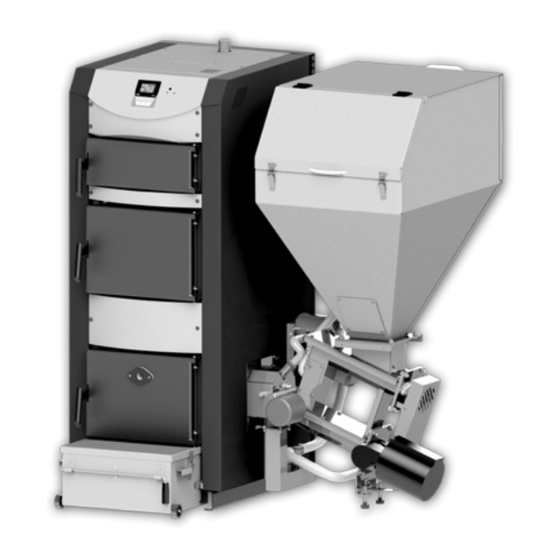
Dual-chamber boiler CombiBurn DC – A series
DE
TECHNISCHER DATENBLATT MONTAGE- und BEDIENUNGSANLEITUNG
Zweikammernkessel Serie CombiBurn DC – A
FR
MANUEL TECHNIQUE INSTRUCTIONS pour L'INSTALLATION et L'EXPLOITATION
Chaudière bi-chambre série CombiBurn DC – A
ES
PASAPORTE TECNICO. INSTRUCCION para МОNTAJE y EXPLOTACION
Caldera de doble-cámara CombiBurn DC – A serie
IT
MANUALE TECNICO. ISTRUZIONE di MONTAGGIO e USO
Caldaia a doppia camera serie CombiBurn DC – A
model:
serial №:
Advertisement
Chapters
Table of Contents

Related Manuals for Sunsystem BURNIT CombiBurn DC-A Series


Summary of Contents for Sunsystem BURNIT CombiBurn DC-A Series
- Page 1 TECHNICAL PASSPORT INSTALLATION and OPERATION MANUAL Dual-chamber boiler CombiBurn DC – A series TECHNISCHER DATENBLATT MONTAGE- und BEDIENUNGSANLEITUNG Zweikammernkessel Serie CombiBurn DC – A MANUEL TECHNIQUE INSTRUCTIONS pour L’INSTALLATION et L’EXPLOITATION Chaudière bi-chambre série CombiBurn DC – A PASAPORTE TECNICO. INSTRUCCION para МОNTAJE y EXPLOTACION Caldera de doble-cámara CombiBurn DC –...
-
Page 2: Table Of Contents
TECHNICAL PASSPORT INSTALLATION and OPERATION MANUAL TABLE OF CONTENTS EXPLANATION OF SYMBOLS AND SAFETY INSTRUCTIONS ..................3 1.1. Explanation of symbols ..............................3 1.2. Requirements to burner installation room ........................3 1.2.1. Instructions to burner installer ............................. 3 1.2.2. Instructions to installation user ........................... 4 1.2.3. Minimum clearances for installation. Combustibility of construction materials ............4 PRODUCT DESCRIPTION ............................... 4 2.1. -
Page 3: Explanation Of Symbols And Safety Instructions
TECHNICAL PASSPORT INSTALLATION and OPERATION MANUAL 1. EXPLANATION OF SYMBOLS AND SAFETY It is mandatory to assure a backup power generator INSTRUCTIONS of corresponding rated power! (see 12.2) Customer must undergo boiler operation/ 1.1. Explanation of symbols maintenance training by authorized installer/ CAUTION! –... -
Page 4: Minimum Clearances For Installation. Combustibility Of Construction Materials
TECHNICAL PASSPORT INSTALLATION and OPERATION MANUAL Set includes Dual-chamber boiler DC-A, pellet burner CW, CAUTION! Hot surface! fuel hopper, removable ash-and-soot container. Risk of burns if you touch the running system. 2.1. Design structure of Dual-chamber boiler CombiBurn DC Burner housing, body and flange are hot surfaces during burner operation. -
Page 5: Design Of Auger Mechanism And Fuel Hopper
TECHNICAL PASSPORT INSTALLATION and OPERATION MANUAL Elements of pellet burner are: of logs, furniture and other products. Wood is the richest raw material which does not have any impact on the production 1 - Burner; 7 - Cleaning system; costs of food products or ethyl alcohol (ethanol). The raw 2 - Air mantle; 8 - Photo-sensor; material is processed under high-pressure and temperature 3 - Screw mechanism; 9 - Fuel hopper flange;... -
Page 6: Transportation
TECHNICAL PASSPORT INSTALLATION and OPERATION MANUAL Table 2. European Certification of Wood Pellets for Heating Purposes Parameters Units ENplus-A1 ENplus-A2 EN-B 6 (± 1) 6 (± 1) 6 (± 1) Diameter 8 (± 1) 8 (± 1) 8 (± 1) Length 15 ≤ L ≤ 40 15 ≤ L ≤ 40 15 ≤ L ≤ 40 Bulk density kg / m ≥ 600 ≥ 600 ≥ 600 Calorific/heating value MJ / kg ≥ 16,5-19 ≥ 16,3-19 ≥ 16,0-19 Humidity /moisture... -
Page 7: Setup Of The Heating Boiler
TECHNICAL PASSPORT INSTALLATION and OPERATION MANUAL Q – boiler output in kW 7.2. Connecting the boiler to the mains power supply - R emove the packaging without polluting the environment Caution! ELECTRIC SHOCK HAZARD! - O bserve building supervision instructions, in particular the - Before opening the unit: switch off the voltage and existing Ordinance on combustion devices and storage of secure the unit against accidental restart. -
Page 8: Connecting The Boiler To The Heating Installation
TECHNICAL PASSPORT INSTALLATION and OPERATION MANUAL 1. Water supply network (pressure 6-10 bar) When the boiler is connected to a heating system, it is 2. Drainage (sewerage) mandatory to install a 3 bar relief valve and expansion vessel. 3. Boiler DC-A No shut-off fittings may be installed between the relief valve, 4. Safety heat exchanger inlet expansion vessel and boiler. 5. BVTS valve sensor It is mandatory to install a three-way valve 6. -
Page 9: Filling The Heating Installation
TECHNICAL PASSPORT INSTALLATION and OPERATION MANUAL - F or assembly and installation of the burner follow the 8. FILLING THE HEATING INSTALLATION requirements in this manual. Table 6 - U se only recommended in this manual fuel. Problem Prevention - C lean ash-and-soot container weekly. Possible installation - D isassemble the burner from the boiler body before clean damage due to strains Fill the heating installation only in it. Depending on fuel and burner settings, clean the pellet in the material caused... -
Page 10: User Menu
TECHNICAL PASSPORT INSTALLATION and OPERATION MANUAL Summer mode /shower and sun/ symbol means than The symbol “T” indicates that a room is set Summer heating mode. Only DHW pump is thermostat is connected to the active. controller of the burner (the boiler). In “CH Priority” mode the room thermostat controls the Burner flame symbol appears in upper right part of burner by starting and stopping it. In “DHW Priority” mode display. Means that burner is activated. Burner goes into Ignition mode and upcoming boiler fire up. - Page 11 TECHNICAL PASSPORT INSTALLATION and OPERATION MANUAL 10.2.2. Burner start-up „Switch mode“ Heating priority selection Menu. Burner start-up. After pressing the From this menu you can select the “F” button and using the navigation priority of one of the two pumps: arrows, the “Auto” menu is (CH Priority) or (DHW Priority). selected. Pressing the “F” button Parallel Pumps – parallel operation will open the next page of the of both pumps. Summer Mode.
-
Page 12: Warranty Terms
TECHNICAL PASSPORT INSTALLATION and OPERATION MANUAL 11. WARRANTY TERMS 12. TECHNICAL FEATURES 12.1. Elements of Dual Chamber boiler CombiBurn DC-A The warranty terms are described in the Service booklet included in the supply. 1. Dual-chamber boiler; 10. Mantle; 2. Fuel Hopper; 11. Wood - combustion chamber; 3. -
Page 13: Recycling
TECHNICAL PASSPORT INSTALLATION and OPERATION MANUAL 13. RECYCLING AND WASTE DISPOSAL Obsolete equipment shall be collected separately from other recyclable waste containing materials with adverse 13.1. Recycling of boiler packaging effect on health and environment. Parts of the packaging made of wood or paper can be used as Metal details, as well as non-metal ones shall be sold to combustible for the burner. Submit the rest of the packaging licensed recyclable metal or non-metal waste collection material for recycling according to the local regulations and... - Page 14 TECHNISCHER DATENBLATT MONTAGE- und BEDIENUNGSANLEITUNG INHALT ERLÄUTERUNG VON SYMBOLEN UND SICHERHEITSVORSCHRIFTEN ................15 1.1. Erläuterung von Symbolen ............................15 1.2. Hinweise auf den Raum für Montage des Zweikammernkessels ................15 1.2.1. Hinweise für den Monteur ............................15 1.2.2. Hinweise für Anlagebenutzer ............................. 15 1.2.3. Minimale Abstände bei Montage und Entzündbarkeit von Baumaterialien .............. 16 BESCHREIBUNG VOM ERZEUGNIS ..........................16 2.1. Konstruktion des Zweikammernkessels CombiBurn DC ..................... 16 2.2.
-
Page 15: Erläuterung Von Symbolen Und Sicherheitsvorschriften
TECHNISCHER DATENBLATT MONTAGE- und BEDIENUNGSANLEITUNG 1. ERLÄUTERUNG VON SYMBOLEN UND FEUERGEFAHR wegen entzündbaren Materialien SICHERHEITSVORSCHRIFT oder Flüssigkeiten. - Entzündbare Materialien oder Flüssigkeiten dürfen 1.1. Erläuterung von Symbolen in unmittelbarer Nähe des Zweikammernkessels ACHTUNG! – Wichtiger Hinweis oder Mahnung nicht stehen. bezüglich der Sicherheitsbedingungen bei Montage, - Weisen Sie an dem Benutzer der Anlage die gültige Installierung und Nutzung des Zweikammernkessels... -
Page 16: Minimale Abstände Bei Montage Und Entzündbarkeit Von Baumaterialien
TECHNISCHER DATENBLATT MONTAGE- und BEDIENUNGSANLEITUNG - S tellen Sie keine brennbare Gegenstände auf dem Kessel 2. BESCHREIBUNG VOM ERZEUGNIS oder in seinem Nähe auf. (sieh Schema für die minimale Schema 2 Abstände) - B ewahren Sie keine brennbare Materialien im Kesselraum Der hocheffektive Zweikammernkessel ist für die Heizung auf. -
Page 17: Automatisches System Für Aschenableitung. Aschenbehälter
TECHNISCHER DATENBLATT MONTAGE- und BEDIENUNGSANLEITUNG Kesselbetrieb. Der Brennvorgang wird elektronisch 2.2. Automatisches System für Aschenableitung. kontrolliert durch Schritten-Modulieren von Brennerbetrieb Aschenbehälter. in Übereinstimmung mit dem Energiebedarf und steht immer in einer optimalen Betriebart. Zwei Schema 3 selbstständige Thermostaten des Kessels (Typ STB) und Das speziell entwickelte System für Aschenleitung erlaubt Schneckenmechanismus (Bimetall-Thermostat eingestellt eine Führung der Asche im unteren Teil (1) des Kesselkörpers auf 80°С) stoppen den Brennstoffvorschub im Brenner falls... -
Page 18: Transportierung Von Kessel
TECHNISCHER DATENBLATT MONTAGE- und BEDIENUNGSANLEITUNG und sehr niedriges Niveau von Kohlenmonoxid in den Wir empfehlen Pellets mit Durchmesser 6-8 mm, Dichte 600- verbrannten Gasen. 750 kg/m³ Kaloriegehalt 4,7-5,5 kWh/kg. Aschegehalt – nicht mehr als 1% und Feuchtigkeit bis 8%, EN 14961-2:2011. Verlangen Übereinstimmungsdeklaration Die optimale Dichte der Pellets, welche seine Qualität und Zertifikat vom akkreditierten Labor bei garantiert, ist im Bereich 605 - 700 kg. /m³. Pelletseinkauf und vergewissern Sie sich, daß der Die Pelletsfeuchtigkeit darf nicht mehr als 10% sein. -
Page 19: Kessellieferung
TECHNISCHER DATENBLATT MONTAGE- und BEDIENUNGSANLEITUNG 5. KESSELLIEFERUNG Rauchabführung bei allen Umständen bereitstellen. Für die richtige Arbeit des Kessels ist die richtige Bemessung · Prüfen Sie bei der Lieferung die Ganzheit der Verpackung. von dem selben Schornstein erforderlich, weil von seiner · Prüfen Sie, ob Sie alle Komponenten erhalten haben. Die Zugkraft die Verbrennung, die Leistung und das Leben des Kessellieferung enthaltet: Kessels abhängt. 1) Kessel mit Brenner, Bunker und im Bunker gestellten Die Zugkraft des Schornsteins ist funktionell abhängig Aschenbehälter von seinem Durchschnitt, Höhe und Rauheit der... -
Page 20: Zusammenfügung Vom Absicherungswärmeaustauscher
TECHNISCHER DATENBLATT MONTAGE- und BEDIENUNGSANLEITUNG Der Zweikammernkessel WBS ist mit einem Absicherungs- Bei Gewitter schalten Sie die Anlage vom Stromnetz Wärmeaustauscher ausgerüstet (Abkühlungskreis). Er wird aus, mit dem Ziel Schutz vor dem Stromschlag. mit einem thermostatischen Ventil zum Wasserleitungsnetz Die falsche Kabelschaltung kann den Regler angeschlossen. Bei Überhitzung, läßt der thermostatische beschädigen. -
Page 21: Füllen Der Heizanlage
TECHNISCHER DATENBLATT MONTAGE- und BEDIENUNGSANLEITUNG Beim Erreichen von Temperatur 95°С wird die thermostatische Havarieschutzvorrichtung betätigt und stoppt die Arbeit vom Lüfter. Um die Schutzvorrichtung zu erneuern, beseitigen Sie den schwarzen Knopf Der Sicherheits STB- Thermostat ist betätigt. auf der vorderen Platte des Kessels und drücken Sie die Taste für STB- Thermostat. -
Page 22: Mikroprozessorsteuerung
TECHNISCHER DATENBLATT MONTAGE- und BEDIENUNGSANLEITUNG möglichen Beginn oder Unterbrechung vom Brennvorgang. Druckknopf „Enter” – dient zum Übergang von einer zu Die Leistung, mit der der Brenner funktioniert, wird von anderen Reihe im Menü des Kontrollers. den vorher angegebenen Parameter im Steuerungsblock Druckknöpfe “Navigationszeiger nach oben” bestimmt, indem der Kaloriegehalt, die Größe und die Dichte vom Brennstoff berücksichtigt werden. und „Navigationszeiger nach unten” – dienen zu Veränderung vom Wert dem konkreten Parameter vom Selbstreinigungssystem... -
Page 23: Benutzermenü
TECHNISCHER DATENBLATT MONTAGE- und BEDIENUNGSANLEITUNG Dieses Symbol im oberen rechten Teil des Displays von heißem Gebrauchswasser (falls einen solchen Kreis zeigt, dass ein Fehler in den normalen Betrieb des verbunden ist); Beleuchtung im Brenner; Zustand vom Kessels aufgetretten ist. Das Blinken des Symbols ist Brenner (ob Fehler festgestellt sind oder nicht); das Datum. auch von einer leisen akustischen Signalisation Mittels Navigationszeiger wird die maximale Temperatur im begleitet. Drücken Sie die Taste „Enter“ so lange bis der Kessel eingestellt. -
Page 24: Garantiebedingungen
TECHNISCHER DATENBLATT MONTAGE- und BEDIENUNGSANLEITUNG 10.2.3. Automatische Betriebsart „Auto“ 10.2.6. Einstellung von manueller Betriebsart „MANUAL” Der Brenner kommt Vom Anfangsmonitor kommen Sie automatische Betriebsart „Auto“. mit Tastendruck „F” in den Die Betriebsart ist die automatische Zustände des Brenners “Switch Mode”. Durch die Navigationszeiger Anzündung und der automatische Brennvorgang, auch automatische wählen Sie das Menü “Manual”... -
Page 25: Technische Charakteristiken
TECHNISCHER DATENBLATT MONTAGE- und BEDIENUNGSANLEITUNG 12. TECHNISCHE CHARATERISTIKEN 12.1. Elemente von Zweikammernkessel CombiBurn DC Schema 11 1. Zweikammernkessel; 10. Wassermantel; 2. Bunker; 11. Brennkammer für Holz; 3. Förderschnecke; 12. Metallgitter; 4. Brenner für Pellets; 13. Brennkammer für Pellets; 5. Mikroporzessorsteuerung; 14. -
Page 26: Recycling
TECHNISCHER DATENBLATT MONTAGE- und BEDIENUNGSANLEITUNG 13. RECYCLING UND AUSWURF Die alte Geräte müssen getrennt von den anderen Abfällen für Recycling der Materialien gesammelt werden. Diese 13.1. Recycling von Kesselverpackung Materialien enthalten Stoffe, die schlecht auf die Gesundheit Teile von der Verpackung, die von Holz oder Papier sind, und Umweltschutz wirken. Die Metall,- und Nichtmetallteile können für Verbrennung im Kessel benutzt werden. Geben werden an lizenzierte Organisationen für Sammlung von Sie das restliche Verpackungsmaterial zur Bearbeitung Metall,- und Nichtmetallabfälle verkauft, welche Teile für gemäß der örtlichen Vorschriften und Anforderungen. - Page 27 MANUEL TECHNIQUE INSTRUCTIONS pour L’INSTALLATION et L’EXPLOITATION TABLES DES MATIÈRES EXPLICATION DES SYMBOLES ET INSTRUCTION DE SÉCURITÉ ..................28 1.1. Explication des symboles ............................... 28 1.2. Exigences relatives à l’emplacement d’installation de la chaudière bi-chambre ............28 1.2.1. Instructions à l’installateur ............................28 1.2.2. Instructions à l’utilisateur du système........................... 29 1.2.3. Distances minimales d’installation et l’inflammabilité des matériaux de construction ..........29 DESCRIPTION DU PRODUIT ............................. 29 2.1. Structure de la chaudière bi-chambre CombiBurn DC - А ....................
-
Page 28: Explication Des Symboles Et Instruction De Sécurité
MANUEL TECHNIQUE INSTRUCTIONS pour L’INSTALLATION et L’EXPLOITATION 1. EXPLICATION DES SYMBOLES ET INSTRUCTION DE ATTENTION! L’installation et le réglage de la SÉCURITÉ chaudière ne doivent être effectués que par un service autorisé et spécialiste en suivant les 1.1. Explication des symboles instructions de sécurité... -
Page 29: Instructions À L'utilisateur Du Système
MANUEL TECHNIQUE INSTRUCTIONS pour L’INSTALLATION et L’EXPLOITATION - N e placez pas des objets inflammables sur la chaudière 2. DESCRIPTION DU PRODUIT ou dans sa proximité. (Voir le schéma pour les distances Schéma 2 minimales). - N ’entreposez pas de matériaux inflammables dans la La chaudière bi-chambre de haute efficacité est conçue pour chaufferie. -
Page 30: Système Automatique À L'évacuation De La Cendre. Conteneur À Cendre
MANUEL TECHNIQUE INSTRUCTIONS pour L’INSTALLATION et L’EXPLOITATION voies des gaz de combustion, la chaudière atteint une 2.5. Les dispositifs de sécurité de la chaudière bi-chambre. efficacité jusqu’à 89% et ménage l’environnement avec Les dispositifs de sécurité assurent un fonctionnement faibles émissions de carbone. fiable de la chaudière. La combustion est contrôlée électroniquement par... -
Page 31: Transport De La Chaudière
MANUEL TECHNIQUE INSTRUCTIONS pour L’INSTALLATION et L’EXPLOITATION 10% par rapport de 20% à 60% teneur en humidité dans le kWh/kg. Teneur en cendres – pas plus de 1% et teneur en bois coupé). La faible humidité, les portions de combustible humidité jusqu’à 8%, EN 14961-2:2011. contrôlées et l’air régulé précisément signifient une La densité optimale des granulés garantissant leur qualité est combustion à haut rendement et très faible niveau d’oxydes dans la plage de 605 à 700 kg sur m ³ de carbone dans les gaz d’échappement. La teneur en humidité dans les granulés ne doit pas dépasser 10%. Assurez-vous que l’endroit de stockage du combustible En achetant de granulés, exigez une déclaration de est sec et frais. conformité et certificat du laboratoire accrédité, et La quantité optimale de cendres dans les granulés soit ≤ 1%. -
Page 32: Livraison De La Chaudière
MANUEL TECHNIQUE INSTRUCTIONS pour L’INSTALLATION et L’EXPLOITATION permettra son nettoyage et son entretien aussi facilement Tableau 3. Dimensions gabarits: chaudière CombiBurn 30 que possible; kW, brûleur, mécanisme à vis sans fin, trémie et récipient - L ’installation doit être exécutée selon le schéma de cendre. d’assemblage 1, qui est présenté avec un revêtement inclus à la chaudière; - A ucun des objets faits de matières inflammables ou liquides A, mm B, mm C, mm D, mm Poids, kg ne doit pas être placé sur/près de la chaudière;... -
Page 33: Schémas De Raccordement De La Chaudière Et Du Brûleur Au Réseau Électrique
MANUEL TECHNIQUE INSTRUCTIONS pour L’INSTALLATION et L’EXPLOITATION 7.3. Raccordement de l’échangeur de chaleur de sécurité 7.2. Schémas de raccordement de la chaudière et le brûleur au réseau électrique. Effectué par un spécialiste autorisé à cette fin/ centre de service. Attention! COURANT ÉLECTRIQUE! - Avant d’ouvrir l’appareil: éteignez la tension La chaudière bi-chambre CombiBurn DC - А est équipé... -
Page 34: Remplissage Du Système De Chauffage
MANUEL TECHNIQUE INSTRUCTIONS pour L’INSTALLATION et L’EXPLOITATION Haute température de l’eau de chaudière et en même temps basse température des radiateurs. 1. Résistance hydraulique est trop élevée Assurez-vous que la pompe de circuit est bien choisie et le système 2. Air dans le système de chauffage est bien dimensionné... -
Page 35: Fonctionnement De La Chaudière
MANUEL TECHNIQUE INSTRUCTIONS pour L’INSTALLATION et L’EXPLOITATION 9. FONCTIONNEMENT DE LA CHAUDIÈRE la chaudière s’accomplit par un installateur agréé ou un centre de service. Dans le cas de non-respect de l’installation - I l est obligatoire de faire chaque année un contrôle complet et d’exploitation décrits dans le manuel et la et un nettoyage de tous les composants du brûleur et la brochure, la garantie est annulée. -
Page 36: Menu D'utilisateur
MANUEL TECHNIQUE INSTRUCTIONS pour L’INSTALLATION et L’EXPLOITATION Explication des boutons: les sondes de température respectives. Ce symbole apparaît dans le coin droit supérieur de Ce symbole signifie „Mode d’été“ de chauffage. l’écran et signifie que la chaudière est dans le mode Uniquement la pompe de chauffage d’ECS est active. de nettoyage automatique. Ce symbole dans le coin droit supérieur de l’écran La présence de ces deux caractères à la place de signifie que le réchauffeur du brûleur fonctionne. Le l’indication de la température dans la chaudière brûleur est en veille d’allumage et après l’allumage de la... - Page 37 MANUEL TECHNIQUE INSTRUCTIONS pour L’INSTALLATION et L’EXPLOITATION Réglez le mode de priorité du Parallel Pumps – le travail parallèle des deux pompes. brûleur à l’aide de „flèches de Summer Mode - Mode d’été. Important – L’utlisation de navigation”. l’option „Thermostat de chambre externe du brûleur” est - CH Priority – priorité de la pompe active si l’option est sélectionnée (CH Priority – la priorité de du système de chauffage.
-
Page 38: Conditions De Garantie
MANUEL TECHNIQUE INSTRUCTIONS pour L’INSTALLATION et L’EXPLOITATION 11. CONDITIONS DE GARANTIE Les conditions de garantie sont décrites dans le livret d’entretien, joint à l’ensemble. 12. CARACTÉRISTIQUES TECHNIQUES 12.1. Éléments de chaudière bi-chambre CombiBurn DC - А Schéma 11. Éléments de chaudière bi-chambre DC 1. Chaudière bi-chambre; 10. Chemise d’eau; 2. Trémie; 11. Chambre de combustion à bois bûches; 3. -
Page 39: Recyclage Et Élimination
MANUEL TECHNIQUE INSTRUCTIONS pour L’INSTALLATION et L’EXPLOITATION Hauteur / Largeur / Profondeur 1105/625/810 Volume de la trémie Réservoir d’eau S, Litres Puissance nominale Puissance consommée en allumage 1600 Puissance consommée en fonctionnement 60÷70 Puissance consommée en nettoyage 1300 Alimentation électrique V/Hz 220 AC / 50 Poids de chaudière Poids de chaudière avec trémie et brûleur Schéma 12 13. RECYCLAGE ET ÉLIMINATION Les appareils usagés doivent être collectés séparément des autres déchets pour le recyclage, 13.1. - Page 40 PASAPORTE TECNICO. INSTRUCCION para МОNTAJE y EXPLOTACION TABLA DE CONTENIDOS EXPLICACIÓN DE LOS SÍMBOLOS Y INSTRUCCIONES DE SEGURIDAD ................41 1.1. Explicación de los símbolos ............................41 1.2. Requerimientos de la sala de calderas .......................... 41 1.2.1. Instrucciones para el instalador ............................. 41 1.2.2. Instrucciones para el usuario ............................41 1.2.3. Espacio mínimo necesario. Combustibilidad de los materiales de construcción ............42 DESCRIPCIÓN DEL PRODUCTO ............................
-
Page 41: Explicación De Los Símbolos Y Instrucciones De Seguridad
PASAPORTE TECNICO. INSTRUCCION para МОNTAJE y EXPLOTACION 1. EXPLICACIÓN DE LOS SÍMBOLOS E INSTRUCCIONES DE Se requiere instalación / servicio autorizado para SEGURIDAD capacitar a los usuarios para el servicio y la limpieza de la caldera. 1.1. Explicación de los símbolos PRECAUCIÓN! –... -
Page 42: Espacio Mínimo Necesario. Combustibilidad De Los Materiales De Construcción
PASAPORTE TECNICO. INSTRUCCION para МОNTAJE y EXPLOTACION - E ste manual se debe conservar durante la vida útil de la 2.1. Diseño de la estructura de las calderas de doble cámara Combi DC - A caldera. Cuerpo de caldera con dos cámaras de combustión. El PRECAUCIÓN! Superfície caliente! -
Page 43: Diseño Del Sinfín I Depósito De Combustible (Pellets)
PASAPORTE TECNICO. INSTRUCCION para МОNTAJE y EXPLOTACION Elementos del quemador de pellets domésticos más comunes son de virutas i serrín de madera, que son los materiales de rechazo de la madera utilizada 1 - Quemador; en la producción de troncos, muebles y otros productos. La 2 - Salidas de aire; madera es la materia prima más rica sin ningún impacto en 3 - Sinfín; los costes de producción de productos alimentarios o alcohol 4 - Ventilador, regulación paso de aire; 5 - Sistema de ignición de pellets - con aire etílico (etanol). La materia prima se procesa sometiéndola caliente;... -
Page 44: Transporte
PASAPORTE TECNICO. INSTRUCCION para МОNTAJE y EXPLOTACION Tabla 2. Certificación Europea de pellets de madera para calefacción Parametros Unidades ENplus-A1 ENplus-A2 EN-B Diametro 6 (± 1) 6 (± 1) 6 (± 1) 8 (± 1) 8 (± 1) 8 (± 1) Longitud 15 ≤ L ≤ 40 15 ≤ L ≤ 40 15 ≤ L ≤ 40 Densidad aparente kg / m² ≥ 600 ≥ 600 ≥ 600 Valor calorífico MJ / kg ≥ 16,5-19 ≥ 16,3-19 ≥ 16,0-19... -
Page 45: Configuración De La Caldera
PASAPORTE TECNICO. INSTRUCCION para МОNTAJE y EXPLOTACION respiradero debe estar protegido con una red o rejilla. Los datos de la tablas son a título indicativo. El El tamaño de la rejilla de ventilación se calcula según la tiraje depende del diámetro, la altura, las secciones fórmula: desiguales a lo largo de la superficie de la chimenea, А... -
Page 46: Conexión Del Disipador De Calor De Seguridad
PASAPORTE TECNICO. INSTRUCCION para МОNTAJE y EXPLOTACION 7.3. Conexión del disipador de calor de seguridad 1. Reddeagua (presión 6-10 bar) 2. Desagüe (alcantarillado) Esta conexión debe realizarla un técnico especialista 3. Caldera DC autorizado para estas operaciones. 4. Entrada intercambiador La caldera de Doble Cámara DC - A está equipada con 5. -
Page 47: Llenado De La Instalación
PASAPORTE TECNICO. INSTRUCCION para МОNTAJE y EXPLOTACION Llama inestable (la fotocélula detecta > 180 unidades al máximo rendimiento) Obstrucción de la cámara de combustión Es necesario limpiar la cámara de combustión con un cepillo por materiales inquemados Es necesario limpiar la fotocélula. Consulte el manual para el procedimiento de Suciedad en la fotocélula limpieza Mal ajuste de la relació... -
Page 48: Menú De Usuario
PASAPORTE TECNICO. INSTRUCCION para МОNTAJE y EXPLOTACION Explicación de la indicación en la pantalla: navegue a la pantalla donde está el error que se mostrará en la esquina inferior izquierda. Después de corregir el Símbolo Autolimpieza. Este símbolo en la esquina problema puede limpiar la pantalla de error que desconecte superior derecha indica que la caldera está en la fuente de alimentación a la caldera durante unos segundos régimen delimpieza automático. - Page 49 PASAPORTE TECNICO. INSTRUCCION para МОNTAJE y EXPLOTACION t=85°C, temperatura del agua caliente sanitaria; Intensidad 10.2.4. Apagada del quemador „Standby“ de la llama al quemador; Estado del quemador (errores Pulsando el botón “F” vamos al detectados, si los hay ) ; Data. menú principal y utilizando las Establecer la temperatura máxima flechas de navegación pueden de la caldera con los botones de seleccionar al menú “Standby” y navegación. Pulsar el botón „F” y...
-
Page 50: Condiciones De Garantia
PASAPORTE TECNICO. INSTRUCCION para МОNTAJE y EXPLOTACION Para seleccionar un modo donde la Importante: Para cada uno de los modos de caldera pasará de modo manual a potencia la configuración óptima del ventilador modo automático, después de la debe ajustarse mediante el uso de un analizador quema de la madera pone un de gases para controlar la cantidad de oxígeno cheque ante Manual + Auto. -
Page 51: Reglage
PASAPORTE TECNICO. INSTRUCCION para МОNTAJE y EXPLOTACION Rango temperatura funcionamiento /Max.temperatura °С 65 ÷ 85 / 95 Temp. de humos (modo funcionamiento) °С 150 ÷ 180 Presión máxima de funcionamiento Entrada agua fría А, mm G1½” / 460 Salida agua caliente B, mm G1½” / 1510 Evacuador calor seguridad entrada/salida K, mm R½” / 1400 F, mm ø 152 / 1260 Tubo J, mm Tubo li mpi eza/inspección/apertura O, mm 200 x 90 Puerta de carga N, mm 200 x 390... - Page 52 MANUALE TECNICO. ISTRUZIONE di MONTAGGIO e USO INDICE SPIEGAZIONE DEI SIMBOLI E ISTRUZIONE DI SICUREZZA ....................53 1.1. Spiegazione dei simboli ..............................53 1.2. Istruzioni per il locale di montaggio della caldaia ......................53 1.2.1. Istruzioni per l’installatore ............................... 53 1.2.2. Istruzioni per l’utente dell’impianto ..........................53 1.2.3. Distanze minime nel montaggio e infiammabilità dei materiali di costruzione .............. 54 DESCRIZIONE DEL PRODOTTO ............................54 2.1. Costruzione della caldaia a doppia camera CombiBurn DC .................... 54 2.2. Sistema automatico di scarico ceneri. Contenitore per ceneri ..................
-
Page 53: Spiegazione Dei Simboli E Istruzione Di Sicurezza
MANUALE TECNICO. ISTRUZIONE di MONTAGGIO e USO 1. SPIEGAZIONE DEI SIMBOLI E ISTRUZIONE DI SICUREZZA È obbligatorio provvedere a un’alimentazione di riserva – generatore, dalla rispettiva potenza! 1.1. Spiegazione dei simboli (vedere 12.2). ATTENZIONE! – Importante raccomandazione o avvertenza riguardante le condizioni di sicurezza per PERICOLO di incendio a causa di materiali o liquidi il montaggio, l’installazione e l’uso della caldaia infiammabili. -
Page 54: Distanze Minime Nel Montaggio E Infiammabilità Dei Materiali Di Costruzione
MANUALE TECNICO. ISTRUZIONE di MONTAGGIO e USO - N on permettere che un cavo elettrico o quello del sensore ATTENZIONE! Non usare contemporaneamente le entri in contatto con parti della caldaia dove la temperatura due camere di combustione. di superficie potrebbe superare i 70°С. Il mantello d’acqua appositamente costruito ricopre - C onservare la presente istruzione durante l’intero periodo completamente la camera di combustione allo scopo di di uso della caldaia. aumentare l’efficienza e il rendimento fino al 89%. -
Page 55: Costruzione Del Bruciatore Con La Coclea
MANUALE TECNICO. ISTRUZIONE di MONTAGGIO e USO nella parte più bassa (1) del corpo caldaia e portarle verso supplementare per acqua (montato sulla parte posteriore il cassetto portacenere (2) tramite una coclea (3) e un del serbatoio combustibile e collegato con un tubo alla meccanismo di mescolamento (9). coclea) con la capacità di 10 litri di acqua, il quale è in grado Il contenitore per le ceneri è provvisto di un manico (4) e di di spegnere un fuoco provocato dal ritorno di fiamma nella rotelle (5) per una maggiore comodità di scarico delle ceneri. coclea e nel serbatoio combustibile. Dopo aver svuotato il contenitore dalle ceneri, accertarsi che • Sicura. In caso di guasto elettrico nel sistema del il coperchio (6) è chiuso saldamente e che è stato fissato al... -
Page 56: Trasporto Della Caldaia
MANUALE TECNICO. ISTRUZIONE di MONTAGGIO e USO Contenuto di particelle fini – non più dell’1% e umidità fino All’acquisto di pellet chiedere una dichiarazione all’8%., EN 14961-2:2011. di conformità e un certificato da laboratorio La densità ottimale dei pellet che garantisce la loro qualità accreditato e accertarsi che il combustibile oscilla tra 605–700 kg/m corrisponde alle esigenze indicate nell’istruzione. ³ Quando si acquista una grande quantità di pellet L’umidità dei pellet non deve superare il 10%. Accertarsi (ad es. -
Page 57: Consegna Della Caldaia
MANUALE TECNICO. ISTRUZIONE di MONTAGGIO e USO 5. CONSEGNA DELLA CALDAIA tiraggio dipende la combustione, la potenza e la vita di servizio della caldaia. • Alla consegna controllare l’integrità dell’imballaggio. Il tiraggio del camino è in dipendenza funzionale dalla sua • Controllare se sono stati ricevuti tutti i componenti. La sezione, altezza e rugosità delle pareti interne. La caldaia consegna della caldaia comprende: deve essere collegata ad un camino indipendente. Il diametro... -
Page 58: Collegamento Dello Scambiatore Di Sicurezza
MANUALE TECNICO. ISTRUZIONE di MONTAGGIO e USO La caldaia viene collegata alla rete elettrica da 220V/50Hz passa attraverso lo scambiatore e fa calare la temperatura mediante un cavo e una spina. della caldaia. Dopo aver effettuato lo scambio termico Per mettere in funzione la caldaia si deve collegare alla rete l’acqua viene buttata via nella fognatura. Lo scambiatore di elettrica da 220V/50Hz mediante una presa di alimentazione. sicurezza garantisce una sicura riduzione del calore eccessivo Stabilire un collegamento fisso alla rete elettrica conforme senza la necessità di energia supplementare. In tale modo alle disposizioni locali (vedere schemi 8 e 9). -
Page 59: Riempimento Dell'impianto Di Riscaldamento
MANUALE TECNICO. ISTRUZIONE di MONTAGGIO e USO La temperatura nella caldaia a cui è montato il bruciatore è bassa. Non può raggiungere regime normale di 65° - 85°С. Consultare immediatamente il vostro installatore per il problema sorto. Inadeguato dimensionamento e/o combinazione Montare all’uscita di scarico Y la valvola di carico/scarico acqua compresa di impianti di riscaldamento. -
Page 60: Comando A Microporcessore
MANUALE TECNICO. ISTRUZIONE di MONTAGGIO e USO controllo per un eventuale avvio o arresto del processo di per passare da una pagina del menù a quella successiva così combustione. come per il passaggio del bruciatore da un regime a un altro La potenza con la quale funziona il bruciatore viene (Manual -Auto – Programe). determinata dagli intervalli impostati in anticipo dalla Tasto „Enter” – serve per passare da una riga del menù centralina di controllo tenendo presente il potere calorifico, del controllore a quella seguente. -
Page 61: Menù Dell'utente
MANUALE TECNICO. ISTRUZIONE di MONTAGGIO e USO eliminato, l’allarme si può cancellare. Il funzionamento - pompa di acqua calda sanitaria. normale della caldaia viene ristabilito staccando per pochi secondi la caldaia dalla rete elettrica e riaccendendola dopo. 10.2. Menù dell’utente Temperatura nella caldaia sopra il limite massimo. 10.2.1. Schermo iniziale „Standby“ L’apparizione di questi due simboli al posto Il bruciatore è in stato di attesa. - Page 62 MANUALE TECNICO. ISTRUZIONE di MONTAGGIO e USO il bruciatore lavora soltanto per riscaldare l’acqua calda Se non è stata fatta una simile sanitaria. selezione, dopo la combustione Tramite le frecce di navigazione selezionare l’opzione della legna la caldaia si spegnerà e desiderata. Con il tasto „Enter” passare alla pagina seguente dovrà essere riaccesa. del menù. Menù Selezione di priorità di riscaldamento. Importante –...
-
Page 63: Condizioni Di Garanzia
MANUALE TECNICO. ISTRUZIONE di MONTAGGIO e USO Importante: ciascuna delle potenze Importante: Si sta utilizzando un bruciatore dove l’impostazione ottimale del ventilatore viene fatta i valori dell’ossido di carbonio sono circa (СО < con l’aiuto di analizzatore di gas controllando la 100 ppm, al 13 % О... -
Page 64: Riciclaggio
MANUALE TECNICO. ISTRUZIONE di MONTAGGIO e USO Altezza / Larghezza / Profondità 1105/625/810 Capacità Serbatoio per acqua S, litri Potenza nominale 1600 accensione Consumo in fase di: funzionamento pulizia 60÷70 1300 Alimentazione elettrica V/Hz 220 AC / 50 Peso caldaia Peso caldaia + serbatoio e bruciatore Schema 12 13. RICICLAGGIO E SMALTIMENTO I componenti di metallo, così come quelli di altro materiale, vengono venduti a aziende autorizzate alla raccolta di rifuti 13.1. Riciclaggio dell impballaggio della caldaia ferrosi e non ferrosi destinati a riciclaggio. Non devono Le parti in legno o in carta dell’imballaggio possono essere essere trattati alla pari con i rifiuti solidi urbani. - Page 65 65 65...
- Page 66 66 66...
- Page 67 67 67...
- Page 68 Screw Photo Sensor Burner 68 68...
- Page 69 69 69...
- Page 70 70 70...
- Page 72 12 Madara Blvd., 129 Vitosha Blvd., 9700 Shumen, Bulgaria 1000 Sofia, Bulgaria t: +359 54 874 555 t: +359 02 952 24 05 f: +359 54 874 556 f: +359 02 952 67 20 e-mail: ftrade@sunsystem.bg e-mail: sunsofia@sunsystem.bg www.sunsystem.bg v. p0.5...
Need help?
Do you have a question about the BURNIT CombiBurn DC-A Series and is the answer not in the manual?
Questions and answers