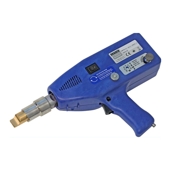
Drader INJECTIWELD W30000 Manual
Hide thumbs
Also See for INJECTIWELD W30000:
- Instructional manual (24 pages) ,
- Instruction manual & user manual (23 pages)
Table of Contents
Advertisement
Quick Links
W30000 REPAIR PROCEDURE UPDATES
Drader Manufacturing Industries Ltd. (Drader) provides no warranty, express or implied, statutory or otherwise as
to the accuracy, and viability of the information, solutions, and opinions provided in this document to anybody.
Contents subject to change without notice.
This is a CONFIDENTIAL AND PROPRIETARY DOCUMENT and should not be distributed outside of the Drader
Injectiweld authorized distributor and/or service centre network and shall be considered confidential information
protected under non-disclosure agreement. DO NOT PROVIDE ANY PART OF THIS DOCUMENT TO END CUSTOMERS
OR ANYONE ELSE!
All trademarked names are the rights of their respective companies.
TRIGGER SWITCH REPLACEMENT
Revision 1.0 / 2022-08-23
5750 – 50 Street NW
Edmonton, AB T6B 2Z8
CANADA
www.drader.com
1327 Clark Boulevard
Brampton, ON L6T 5R5
NOTICE
CANADA
Advertisement
Table of Contents

Related Manuals for Drader INJECTIWELD W30000


Summary of Contents for Drader INJECTIWELD W30000
- Page 1 Contents subject to change without notice. This is a CONFIDENTIAL AND PROPRIETARY DOCUMENT and should not be distributed outside of the Drader Injectiweld authorized distributor and/or service centre network and shall be considered confidential information protected under non-disclosure agreement.
-
Page 2: Table Of Contents
Step 4 – Cable and Air Hose Routing ...................... 19 Step 5 – Cable and Hose Attachment ..................... 20 Step 6 – Final Cleanup of Internals ......................24 ©2022 Drader Manufacturing Industries Ltd. Page 2 of 25 Injectiweld W30000 Repair Instructions R1.0 / Confidential Information... -
Page 3: Introduction
1. Introduction 1. INTRODUCTION ©2022 Drader Manufacturing Industries Ltd. Page 3 of 25 Injectiweld W30000 Repair Instructions R1.0 / Confidential Information... -
Page 4: Revision Information
Please note that these instructions are intended to guide distributors and service centres with completing repairs using the best practices as known to Drader Manufacturing at the time. These best practices are subject to change at any time and this document will be updated accordingly from time to time. -
Page 5: Selecting The Trigger Switch
Use the Trigger Switch with item ID IASS-A-MCSWTRIG when replacing a Trigger Switch on a welder that has the trigger switch wired directly to the PCB. Follow the instructions in SECTION 3 of this document. ©2022 Drader Manufacturing Industries Ltd. Page 5 of 25 Injectiweld W30000 Repair Instructions R1.0 / Confidential Information... -
Page 6: Trigger Switch Replacement For Legacy Welders
2. Trigger Switch Replacement for Legacy Welders 2. TRIGGER SWITCH REPLACEMENT FOR LEGACY WELDERS (DRADER PART NUMBER: IPAR-A-SWTRIG) ©2022 Drader Manufacturing Industries Ltd. Page 6 of 25 Injectiweld W30000 Repair Instructions R1.0 / Confidential Information... -
Page 7: Step 1 - Remove The Old Switch
You may want to inspect all of the wiring to confirm that there is no damage to the trigger wires further inside the welder. ©2022 Drader Manufacturing Industries Ltd. Page 7 of 25 Injectiweld W30000 Repair Instructions R1.0 / Confidential Information... -
Page 8: Step 2 - Trim And Prepare Existing Wires
The lever wire nuts on the end of the wires have a strip guide on the side that you can use to measure if you prefer. ©2022 Drader Manufacturing Industries Ltd. Page 8 of 25 Injectiweld W30000 Repair Instructions R1.0 / Confidential Information... - Page 9 2. Trigger Switch Replacement for Legacy Welders ©2022 Drader Manufacturing Industries Ltd. Page 9 of 25 Injectiweld W30000 Repair Instructions R1.0 / Confidential Information...
-
Page 10: Step 3 - Attach Switch To The Wiring
Take the new switch and open the orange levers on the end of the wires. This will open the wire nut, and then place one wire into each wire nut. It is not important which wire goes to which. ©2022 Drader Manufacturing Industries Ltd. Page 10 of 25 Injectiweld W30000 Repair Instructions R1.0 / Confidential Information... -
Page 11: Step 4 - Screw Switch Into Place
Step 4 – Screw Switch Into Place Using the screw that was used previously to hold the trigger switch, place the trigger switch and screw the switch into place. ©2022 Drader Manufacturing Industries Ltd. Page 11 of 25 Injectiweld W30000 Repair Instructions R1.0 / Confidential Information... -
Page 12: Step 5 - Cable Management
Cord Strap. The trigger switch wires should be pushed into the space between the switch and the rod feed tube as shown below. ©2022 Drader Manufacturing Industries Ltd. Page 12 of 25 Injectiweld W30000 Repair Instructions R1.0 / Confidential Information... - Page 13 The installation is now complete and the enclosure reassembly and testing can continue as required. If the welder under repair had baffles please ensure they are back in place prior to enclosure reassembly. ©2022 Drader Manufacturing Industries Ltd. Page 13 of 25 Injectiweld W30000 Repair Instructions R1.0 / Confidential Information...
-
Page 14: Trigger Switch Replacement For Welders With Pcb Revision 6 Or Later
3. Trigger Switch Replacement for Welders With PCB Revision 6 3. TRIGGER SWITCH REPLACEMENT FOR WELDERS WITH PCB REVISION 6 OR LATER (DRADER PART NUMBER: IASS-A-MCSWTRIG) ©2022 Drader Manufacturing Industries Ltd. Page 14 of 25 Injectiweld W30000 Repair Instructions R1.0 / Confidential Information... -
Page 15: Step 1 - Remove The Old Switch
You may want to inspect all of the wiring to confirm that there is no damage to the trigger wires further inside the welder. ©2022 Drader Manufacturing Industries Ltd. Page 15 of 25 Injectiweld W30000 Repair Instructions R1.0 / Confidential Information... -
Page 16: Step 2 - Trigger Switch Connection
Now connect the switch to the PCB as shown below. This is the reverse of what was done to disconnect and remove the existing switch. ©2022 Drader Manufacturing Industries Ltd. Page 16 of 25 Injectiweld W30000 Repair Instructions R1.0 / Confidential Information... - Page 17 3. Trigger Switch Replacement for Welders With PCB Revision 6 ©2022 Drader Manufacturing Industries Ltd. Page 17 of 25 Injectiweld W30000 Repair Instructions R1.0 / Confidential Information...
-
Page 18: Step 3 - Trigger Switch Attachment
A-EV94) and screw the Trigger Switch into the bottom hole of trigger switch fastening holes until it feels tight. Be careful not to overtighten it as it will strip the plastic. ©2022 Drader Manufacturing Industries Ltd. Page 18 of 25 Injectiweld W30000 Repair Instructions R1.0 / Confidential Information... -
Page 19: Step 4 - Cable And Air Hose Routing
Tube. There is an opening in both Housing halves for the Power Cord, Air Hose and Rod Feed Tube to exit the Housing. ©2022 Drader Manufacturing Industries Ltd. Page 19 of 25 Injectiweld W30000 Repair Instructions R1.0 / Confidential Information... -
Page 20: Step 5 - Cable And Hose Attachment
The screwdriver handle shown in the picture below is there to provide guidance for the cable and provide just a little bit of slack. ©2022 Drader Manufacturing Industries Ltd. Page 20 of 25 Injectiweld W30000 Repair Instructions R1.0 / Confidential Information... - Page 21 Taking a 7” Cable Tie and a pair of needle nose pliers and side cutters. Place the 7” Cable Tie around the Power Cord wires, Trigger Switch wires, Air Hose and Rod Feed Tube as shown below. ©2022 Drader Manufacturing Industries Ltd. Page 21 of 25 Injectiweld W30000 Repair Instructions R1.0 / Confidential Information...
- Page 22 Air Hose. Now push any trigger wire that might be showing underneath of the air and rod feed tubes. ©2022 Drader Manufacturing Industries Ltd. Page 22 of 25 Injectiweld W30000 Repair Instructions R1.0 / Confidential Information...
- Page 23 3. Trigger Switch Replacement for Welders With PCB Revision 6 ©2022 Drader Manufacturing Industries Ltd. Page 23 of 25 Injectiweld W30000 Repair Instructions R1.0 / Confidential Information...
-
Page 24: Step 6 - Final Cleanup Of Internals
©2022 Drader Manufacturing Industries Ltd. Page 24 of 25 Injectiweld W30000 Repair Instructions R1.0 / Confidential Information... - Page 25 3. Trigger Switch Replacement for Welders With PCB Revision 6 Now put the rest of the enclosure together as per the instructions provided elsewhere. ©2022 Drader Manufacturing Industries Ltd. Page 25 of 25 Injectiweld W30000 Repair Instructions R1.0 / Confidential Information...
Need help?
Do you have a question about the INJECTIWELD W30000 and is the answer not in the manual?
Questions and answers