
Subscribe to Our Youtube Channel
Related Manuals for Smipack FP6000


Summary of Contents for Smipack FP6000
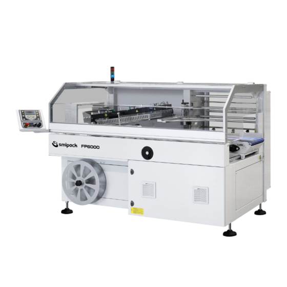
- Page 1 FP6000 - FP6000CS - FP8000CS Automatic L-sealer wrapping machine Use and maintenance manual Translation from the original Manual code: DM211386 Revision: 0...
- Page 2 Rev. Date revision 02.09.2019...
-
Page 3: Table Of Contents
Summary - MARKING AND LABELLING EC Declaration of conformity (Directive 2006/42/EC - Annex IIA) ......7 CE Marking . - Page 4 Moving and unpacking operations ..........26 Positioning and leveling .
- Page 5 Adjustment of film waste guide ........... 56 Insertion of film inside drag and waste collection devices .
-
Page 7: Marking And Labelling
1 - MARKING AND LABELLING SMIPACK with headquarters in Via Piazzalunga 30 - San Giovanni Bianco - Bergamo (Italy) declares to be the manufacturer of the machine object of this manual . This declaration is performed by: - EC Declaration of conformity... -
Page 8: Ce Marking
1 - Marking and labelling 1.2 CE Marking A label placed on the electrical panel of the machine reports information about the marking. 1.3 Validity of marking All risks connected and, therefore, all the safety features, guards and the possibilities of intervention on the machine as a whole were analyzed and realized only for the specific configurations described in this manual. -
Page 9: General Information
2 - GENERAL INFORMATION 2.1 Preface While thanking for choosing us, SMIPACK S.p.A. is pleased to welcome you among its large range of customers, hoping that the use of this machine will fully satisfy you. This manual can be used for the model FP6000-FP6000CS-FP8000CS It has been drawn up to put you in conditions to be able to intervene on the various parts, and to understand the various maintenance and intervention operations. -
Page 10: Predispositions By The Customer
2 - General information 2.3 Predispositions by the customer Are provided by the customer: • the predisposition of a suitable place according to local regulations in force governing health and safety in the workplace. • any possible building work. • the machine positioning in a dry, clean and free of obstructions area. -
Page 11: Description Of The Machine
3 - DESCRIPTION OF THE MACHINE The FP6000 - FP6000CS - FP8000CS series is especially recommended bagging individual packs or group of products in a single package by using centre-folded film thanks to L-sealing made with a sealing bar. The machine can also be... -
Page 12: Description Of The Keys On The Operator Panel
3 - Description of the machine 3.2 Description of the keys on the operator panel a - Display b - START key c - STOP key d - Emergency e - Selector f - USB connection Fig. 3.2.1 For more information about the operator panel controls... -
Page 13: Electrical System
3.4 Electrical system The electrical system is composed of: - an electrical panel for system management; - an operator interface on board machine; - a series of junction boxes, electrical seats on board machine, wiring and cables. It is manufactured according to IEC 60204-1 norm. The electric cabinets are able to provide the protection of materials against external agents (IP54 protection level). -
Page 14: Pneumatic System (Applicable Only For Optional Systems)
3 - Description of the machine Electrical installation data Install a circuit breaker on the machine power supply line which supports the values indicated in the table. FP6000 - FP6000CS FP8000CS 380÷415 V 220÷240 V 380÷415 V 220÷240 V Nominal... - Page 15 Pneumatic system adjustements In order to have air flow inside the pneumatic system, act on the isolator (1) and then turn the knob of the regulator (2) checking the pressure gauge (4) to control the pressure level reached. The machine also has a pressure switch installed on it located inside the electrical control board which, in the event of an air shortage inside the system, indicates this anomaly on the operator panel.
-
Page 17: Manual Structure
This manual were compiled by SMIPACK S.p.A. in its original language and translated into several languages starting from the original version in Italian. If contradictions arise caused by the different language versions, reference must be made to the original version in italian. -
Page 18: Preservation Of The Manual
4 - Manual structure Any updates or integrations of the manual will be considered an integral part of it. We would like to thank you in advance for any suggestions which you would like to point out to us in order to implement further improvement. -
Page 19: Symbols Key
4.9 Symbols key For an easy reading of the manual were used some symbols of which below it gives the meaning. ATTENTION! This indicates personal hazardous situations and suggests standards of conduct. WARNING! This indicates situations of risk for the machine and/or for the product being processed. -
Page 21: Data And Technical Features
Size of the products that can be wrapped You can check the max permitted length and width of a product in relation to its height. The weight of the products to be packed must not exceed 30 kg. FP6000 HEIGHT H LENGTH X... -
Page 22: Features Of The Film And Reel Dimensions
Ø maximum reel : 350 mm Width (L) maximum reel: - 600 mm (FP6000 - FP6000CS) - 850 mm (FP8000CS) 5.3 Film reel width calculation For each change format, depending on the dimensions Y and H of the product to be packaged it is necessary to calculate the range of reel. - Page 23 ATTENTION! The exposure of the operator to noise may also vary due to background noise generated by other equipment present where the machine is installed. In order to provide operators with the appropriate PPE hearing protection it may therefore be necessary to assess the noise within the work environment.
-
Page 25: Machine Installation
- do not put over the machine boxes, cases or heavy equipment; - do not place the components close to flammable material. SMIPACK S.p.A. is not responsible for any event caused after the machine is delivered to the forwarder company. -
Page 26: Moving And Unpacking Operations
6 - Machine installation 6.4 Moving and unpacking operations SMIPACK S.p.A., depending on the mode of transportation and products to be delivered, uses adequate packaging to guarantee integrity and preservation during transportation. Fig. 6.4.1 The carrier is liable for damage sustained during transportation. - Page 27 WEIGHT AND DIMENSIONS OF PACKED MACHINE Fig. 6.4.2 FP6000 FP6000CS FP8000CS X : 2200 mm X : 2200 mm X : 2650 mm Y : 1640 mm Y : 1640 mm Y : 1990 mm H : 1525 mm H : 1525 mm...
-
Page 28: Positioning And Leveling
6 - Machine installation 6.5 Positioning and leveling Make sure that the floor where the machine will be installed is not uneven, impairing its normal and correct positioning. Remove the supports (1) which fix the machine to the pallet and then level the machine carefully placing a level on the frame at the points shown in the figure. -
Page 29: Assembly Carried Out By User
Height adjustment of the machine's work surface varies depending on the model: - from 785 mm to 945 mm for FP6000 - FP6000CS - from 815 mm to 975 mm for FP8000CS The machine can also be equipped with wheels which must be used only to facilitate eventual movements. -
Page 30: Assembly Of Light Column
To release the arm and reposition the operator panel correctly follow the instructions below, according to the model of machine purchased. >FP6000 - FP6000CS • Remove the sheet metal bracket (10) by acting on the screws (11) and (12). - Page 31 >FP8000CS • Loosen the screw (14) that secures the arm on which the operator panel is fitted. Fig. 6.6.5 • Turn the operator panel towards the outside of the machine as shown in picture 6.6.6 and then secure the arm in this position, again using the screw (14). •...
-
Page 32: Electrical Connection Of The Machine
6 - Machine installation 6.7 Electrical connection of the machine Power must be cut from the machine for all operations involving connection to the electrical network. These operations must be carried out by qualified personnel. Before accessing the electrical system it is mandatory to switch off power supply and wait at least 5 minutes before handling. - Page 33 > Use the machine with the srink tunnel In case of which on the outfeed side of the machine is installed the shrink tunnel it is necessary to fix it to the packaging machine. Adjust the height of the sealer so that its outfeed belt is 1 mm lower than the tunnel belt to keep packs from dropping during the passage.
-
Page 34: Fine Tuning Operations And First Start Of The Machine
6 - Machine installation 6.10 Fine tuning operations and first start of the machine Before using the machine, make sure that are correctly assembled all those parts which for transportation purposes are responsibility of the end user. (see paragraph 6.6). With the machine off, check the fixing of the main components of the machine which could be accidentally loosened during transportation. -
Page 35: Use Of The Machine
7 - USE OF THE MACHINE 7.1 Function description • In the infeed area the guides provide to channel the loose containers transported by a first conveyor belt. • The containers pass under the large metal squares where are wrapped with the film; the unwinding of the film reel is controlled by a special motor and a tensioning bar unit equipped with rollers that allows the correct tensioning of the film while another device allows the drag. -
Page 36: Prohibitions And Precautions
7 - Use of the machine 7.2 Prohibitions and precautions For the proper use of the machine it is necessary to comply the prohibitions and cautions provided in this paragraph. IT IS PROHIBITED TO: • Introduce any part of your body inside the machine while it is running. •... -
Page 37: Intended Use Of The Machine And Not Permitted Uses
Depending on the machine model it is possible to meet the following maximum productions: • up to 50 packs / minute for FP6000 • up to 60 packs / minute for FP6000CS •... -
Page 38: Operator Points
The manufacturer do not assumes the responsibility for failure to comply with this requirements. If required please contact SMIPACK before any eventual change to the relative consent. -
Page 39: Safety Devices Adopted
• use the machine without verifying the existence of the minimum spaces required; this conduct can cause accidents because the operator, by acting in confined spaces, may run into impacts or stumbles. Inadequate reactions due to equipment failure, accidents, etc. An alarm is triggered every time an operation failure or fault is detected on the machine. -
Page 40: Doors Magnetic Sensors (3)
7 - Use of the machine 7.6.2 Doors magnetic sensors (3) Are opening doors anchored to the structure of the machine equipped with magnetic sensors that disable the movement of all devices considered hazardous: • sealing bar operation • operation of conveyor belts >... -
Page 41: Operating Controls Via Software
7.6.4 Operating controls via software Each time the machine is switched on performs controls to verify some operating positions (sealing bar movement) by means of a self-calibration prodecure. 7.7 Safety pictograms Near some particular zones of the machine, some pictograms were placed in order to recall the attention of the operators concerning the precautions required to avoid dangers. -
Page 42: Risk Centers
7 - Use of the machine 7.8 Risk centers the risk centers of the machine are reported here below: A) Machine infeed zone (entanglement, dragging, crushing) B) Reel holder and unwinder film zone (abrasions, cutting, small perforations, crushing, entanglement, dragging) C) Sealing bar zone (burns, crushing) D) Cutting blade zone (cutting) E) Film waste collection device zone (entanglement, dragging, cutting) - Page 43 ZONE A: Machine infeed Residual risk: Crushing, scraping and dragging of upper limbs due to contact with moving mechanical organs (infeed conveyor belt and film reel unwinder) Prescribed standards of conduct: Do not touch the infeed belt or products in transit while the machine is running. Do not place your upper limbs inside the opening where the product passes to avoid entering into contact with moving mechanical organs.
- Page 44 7 - Use of the machine ZONE D-E : Sealing bar and cutting knife Residual risk: Crushing and cutting hazard, if operating near the sealing bar and cutting knife. This risk is partially reduced due to the presence of a device that stops the movement of the sealing bar reopening when it detects the presence of an obstacle that prevents proper operation.
- Page 45 ZONE G: Machine outfeed Residual risk: - crushing, scraping and dragging of upper limbs due to contact with moving mechanical organs (outfeed conveyor belt) - entering into contact with the sealing and cutting danger zones (D) and (E) where the product passes.
-
Page 46: Individual Protections
7 - Use of the machine ZONE I: Opening doors Residual risk: - crushing hands in the operation of door closing. - blow to the head to contact against the door when it is open. Prescribed standards of conduct: Be careful not to hit your head against the open mobile door during adjustments and maintenance. - Page 47 5 - EAR PLUGS OR MUFFS (HEARING PROTECTION) They must be suitable for the operator and comfortable to use in particularly noisy environments that can disturb the operator while he operates the machine.
-
Page 49: Preparing The Machine For Use
8.1 Height adjustment of film conformation squares >FP6000 Adjust the height of the top square (A) with the respective flywheel (1). The top square should be about 5-10 cm higher than the product to be wrapped. - Page 50 8 - Preparing the machine for use >FP6000CS - FP8000CS With the machine in “Manual” operation mode (activated by pressing the "MAN" button on the operator panel) act on the keys to raise or lower the upper square (A) at a >5÷10 mm height respect on the product to be packaged.
-
Page 51: Positioning The Product Guide
8.2 Positioning the product guide The product guide (2) keeps the product at a distance from the side sealing bar (B1) to avoid problems concerning film tensioning. This distance must increased proportionally when increasing height product increased in the case where the sealing tends to open. -
Page 52: Positioning The Infeed Conveyor Belt
(2) previously adjusted and the external guide (5). Fig. 8.3.1 8.4 Adjustment of reel-holder and unwinder unit 8.4.1 Positioning the film >FP6000 Fig. 8.4.1 Make sure you have adjusted the height of the top square. Position the stop (C) so that it remains a distance “X”... - Page 53 Fig. 8.4.2 >FP6000CS - FP8000CS Fig. 8.4.3 Adjust the stop (C) so that the end of the film reel is placed respect on the millimeter ruler (X ) at the same value obtainen on the millimeter ruler (H With this adjustment is obtained a distance “X”, between the tip of upper square and the end of the film reel of approximately half the height of the product to be packaged.
-
Page 54: Inserting The Film Inside The Unwinder Unit
8 - Preparing the machine for use 8.4.2 Inserting the film inside the unwinder unit The film must be inserted inside the unwinding of the machine respecting the unwinding direction (clockwise or anticlockwise) shown in the figure. Fig. 8.4.5 Make sure that the Manual operating mode is selected. -
Page 55: Adjustment Of Micro-Perforators On The Reel-Holder
ATTENTION! If the lever (8) were not to be closed, the guard (F) remains open preventing operation of the machine. On the operator panel display will show the message "UNWINDER OPEN" 8.4.3 Adjustment of micro-perforators on the reel-holder The micro-perforators (G) on the reel-holder of the machine tave the function to improve the shrinking process of the bag. -
Page 56: Adjusting The Film Return Roll
8 - Preparing the machine for use 8.4.5 Adjusting the film return roll Fig. 8.4.9 Adjust the position of the film return roll (P) to half the height of the product to be wrapped, or slightly lower, at the very most. There are specific millimetric lines... -
Page 57: Insertion Of Film Inside Drag And Waste Collection Devices
handle. The presence of the millimetric line (Q3) facilitates this adjustment operation. Fig. 8.6.1 8.7 Insertion of film inside drag and waste collection devices Make sure to have activated “Manual” operating mode. Open the guide rolls (N) manually and then turn the selector switch (O) to also open the two drive wheels (H) and to pass the front part of the two film edges as shown in figure 8.7.2. - Page 58 8 - Preparing the machine for use Press the F1 key to seal the film a first time. Alternate the sealing (F1) and drag (F2) cycles, sealing a few empty bags in order to unwind in a sufficient amount of film to pass inside the guide hook (M) and to follow the path indicated in the figure and to be able to fasten the end of the film waste on the specific flap (8) on the plate of the waste collection device.
-
Page 59: Adjustments To Facilitate The Packaging Of Low Parcks
To remove waste accumulated on the device, unscrew the knob (10) and remove the containment disk (9). If there are tensioning problems with discarded film it is possible to mount a special weight (11) supplied with the machine. Generally there are tensioning problems when using very thick film or unsuitable material. -
Page 60: Adjustment Of Position Of Squares
8 - Preparing the machine for use Fig. 8.8.2 8.9 Adjustment of position of squares The squares normally protrude from the edge of the infeed belt by 5 mm as shown in figure 1. However if you want to wrap the product in the smallest bag possible, the position can be optimised. -
Page 61: Operations Required For Each Format Change
8.10 Operations required for each format change Below the machine adjustments required to change format every time the dimensions of the product being wrapped vary. Mechanical format change: > Adjustmen of the height of the film conformation squares > Adjustment of the position of infeed conveyor belt and product guide >... - Page 62 8 - Preparing the machine for use Fig. 8.11.1 6) Protrusion of both film edges from the drag drive wheels If both film edges (top and bottom) protrude from the drag drive wheels, check that the size of the film reel is suitable and, if needed, move the reel towards the infeed side (**) of the product. 7) Tearing of the seal of sealing bar B1 (side sealing) If the seal created by the sealing bar B1 tears due to excessive tensioning of the film, move the product further away from the sealing bar.
-
Page 63: Operation And Use
9 - OPERATION AND USE 9.1 Description of operator panel KEY FUNCTIONS Switch the machine on and off. Emergency button. SELECTOR Separates the wheels of the dragging device when positioning the film. Inserts power after the machine is turned on. Signals correct power supply to the machine with the indicator light on. - Page 64 9 - Operation and use Stops the machine. Stops the error signal when the cause of the error is eliminated. Keeping the keys pressed simultaneously for about 1 second allows the film to move forward a few cm and to carry out sealing. The function is active only in automatic and semi-automatic mode with the mobile safety guards closed.
-
Page 65: Display Reading
9.2 Display reading Each line of the operator panel displays a variety of information that is described here below: Stored program (M1,M02,....M20) A) DETECTED ERRORS OR ACTIVE EMERGENCIES This part of the display will show all machine messages and errors described in detail in chapter 11 of the manual. -
Page 66: Luminous Signals
9 - Operation and use vers press the key to go back to the software version screen. press the key to go back to the previous screen. menu press the key to go back to enter the selected menu. press the key to modify settings or save them. -
Page 67: Turning The Machine On
9.4 Turning the machine on Turn the master switch at the side of the electrical control board of the machine to ON. The model of the machine together with the version of the software in use will appear on the display for a few seconds, after which the main menu will be viewed. -
Page 68: Procedure To Switch Off The Machine
9 - Operation and use THAT NO OBJECTS AND SPECIALLY PARTS OF THE OPERATOR'S BODY ARE PRESENTS IN THE SEALING ZONE. (danger of crushing, cutting and scalding) When the initial adjustment phase is complete it will be possible to access the MANUAL, SEMI- AUTOMATIC, AUTOMATIC, FREE PASSAGE operating modes on the machine. - Page 69 Fig. 9.7.1 SEALING DRAGGING SQUARES HEIGHT Vers PACKS NUMBER:0 Menu F1 key: Activates film sealing Press the F1 key for one second to carry out a sealing cycle. The sealing operation can be carried out only when the safety door is closed. Do not bypass the safety guards for any reason whatsoever as the sealing bar is very dangerous mechanical device.
-
Page 70: Activating And Stopping The Packaging Cycle
9 - Operation and use 9.8 Activating and stopping the packaging cycle When the film reel has been mounted on the machine and adjustments have been made to the format it is possible to select the “AUTO” operating mode. Press the button to start the wrapping cycle. -
Page 71: Restart The Machine After An Emergency Stop
ATTENTION! Only press in the event of imminent danger or mechanical accident. Pressing the emergency button the machine will stop instantly and the display on the operator panel will show the message "EMERGENCY". Fig. 9.9.1 ACTIVE FORMAT M01 MODEL 01 OPERATION MODE AUTOMATIC MACHINE STATUS... -
Page 72: Access To The Reserved Menus
9 - Operation and use In the edit area will be indicated the minimal and maximal values can be set for each parameter and the previous value. The number of the value to modificate will be shown in red. 9.12 Access to the reserved menus From the main menu, press the push-button until the following message is displayed: Fig. - Page 73 Fig. 9.13.1 MAIN MENU FORMAT PARAMETERS OPERATOR MENU DATA DISPLAY Menu Press to access format choice. (M01..M20) Fig. 9.13.2 FORMAT PARAMETERS FORMAT SELECTION * M01 MODEL 01 Press the key and then, using the keys, choose memory to be activated. The machine can be programmed with a maximum for 20 memories (M01, M02, M03 ..M020).
- Page 74 9 - Operation and use Fig. 9.13.3 FORMAT PARAMETERS SEALING BAR PACK FILM ADJUSTMENT Menu Press and then to display all parameters contained in the menu. 1 - Sealing bar temperature B1 Allows you to configure the temperature of the B1 side sealing bar. You are advised to set the minimum temperature required for good sealing.
- Page 75 Fig. 9.13.5 SEALING BAR B2 SEALING BAR (value from +50°C to 250°C) TEMPERATURE recommended value: 190°C [°C] 3 - Film sealing time This regulates the film sealing time. This parameter greatly influences the performance of the machine and must therefore be correctly adjusted. In fact, the lower the sealing time, the greater the productivity.
- Page 76 SEALING BAR SEALING BAR SPEED (value from 40 to 160%) 6 - Sealing bar opening position (only FP6000) Allows you to adjust the opening position of the sealing bar according to the height of the product to be wrapped. Fig. 9.13.9...
- Page 77 Fig. 9.13.10 PACK MULTIPACK ENABLED 2 - Pack length • Insert in this field the length of the pack to be wrapped (essential when the MULTIPACK function is enabled). • The sealing bar will come into contact with the product if you insert a value that is too low in relation to the size of the product.
- Page 78 9 - Operation and use Fig. 9.13.12 FILM ADJUSTMENT FP6000-FP6000CS : value between 0 and 200 mm FILM ADVANCE (= h PRODUCT) [mm] FP8000CS : value between 0 and 300 mm 2 - Film advance recovery Shows the speed at which the pusher moves. Pusher speed can be adjusted in % from 20 to 80.
- Page 79 This parameter allows you to move the pack further back on the conveyor, reducing the size of the bag in the process. The parameter is particularly useful for when wrapping high packs. Fig. 9.13.15 FILM ADJUSTMENT FP6000-FP6000CS : value between 0 and 200 mm FILM DELAY RECOVERY [mm]...
- Page 80 9 - Operation and use Fig. 9.13.17 FILM ADJUSTMENT SPEED OF CONVEYORS Min 10 Max m/min (50 ÷ 150 %) The maximum speed that can be set may be limited when the machine is installed in continents where the power supply voltage is different. These precautions allow the wrapping machine to always be able to operate in optimal conditions.
- Page 81 Fig. 9.13.18 CONFIG. PARAMETERS SELECT CONTINENT EUROPE The selection of the CONTINENT is normally carried out by the manufacturer during test inspection. However, should malfunctioning occur on the conveyor belts and/or in case of need, proceed with re-configuration. >OPTIONS A number of settings are managed with this menu, allowing you to improve the product packaging operations.
- Page 82 9 - Operation and use - INTERMITTENT : the infeed belt operates intermittently Using this mode is recommended only to package products that are lower than 2 cm in height and that are detected by the vertical photocell. - In "SOFT START" mode, the infeed belt runs at a more moderate speed. Use soft start mode in the case of superimposed products and only when the conditions demand it, as this work mode reduces productivity.
- Page 83 4 - Mark reading photocell offset (optional) To use this parameter you need to contact SmiPack S.p.A. and purchase the optional "MARK READING SENSOR" unit. Fig. 9.13.22 OPTIONS FILM MARK OFFSET [mm] 5 - Machine operation This menu allows you to select the machine work mode (automatic, semi-automatic, free passage).
- Page 84 9 - Operation and use Fig. 9.13.24 OPTIONS MOTION INVERSION OF THE INFEED CONVEYOR (Value from 0 to 300) [mm] 7 - Film perforation distance (available with the optional “Film Perforator”) If the optional group "Film perforator" is installed, this parameter allows to adjust the distance of the film perforation as needed (linked to dimensions of the product to be packed) Fig.
- Page 85 9 - Film end photocell (optional) With this parameter you can enable or disable the operation of the photocell that alerts the operator of the exhaustion of film reel. Fig. 9.13.27 OPTIONS FILM END PHOTOCELL DISABLED 10 - Save product photocell (optional) With this parameter you can enable the horizontal "Save product photocell"...
- Page 86 7 - Position of the film return roll : insert the position of the film return roll. >OUTSIDE BELTS (optional) This menu can be used exclusively with equipment manufactured by SMIPACK. The menu allows you to configure the outside conveyor belts and manage them through the packaging system operator panel.
- Page 87 2 - Pre-set outside infeed belt speed (A) This allows you to adjust the speed of the outside conveyor belt located in front of the packaging system. Fig. 9.13.30 OUTSIDE BELTS OUTSIDE PRE-SETTING INFEED BELT SPEED 3 - Turn on time for the outside infeed belt (B) This allows you to set the turn on times for the outside conveyor belt located in front of the packaging system.
- Page 88 9 - Operation and use 5 - Outside outfeed belt operation With this menu you can choose the operating mode for the outside conveyor belt located at the end of the machine: - PREREGULATED SPEED : the outside conveyor belt operates at the pre-set speed through the (D) parameter.
- Page 89 Fig. 9.13.35 OUTSIDE BELTS OUTSIDE PRE-SETTING OUTFEED BELT SPEED CONTINUOUS >SAVE FORMAT Using the "SAVE FORMAT" menu it is possible to copy the data from one memory to another and assign it the name you wish. Fig. 9.13.36 FORMAT PARAMETERS SAVE FORMAT _ _ _ _ _ _ _ _ _ _ _ _ _ _ _ _ _ Press the...
- Page 90 9 - Operation and use Fig. 9.13.38 FORMAT PARAMETERS FORMAT NAME *M01 BOTTLE Use the keys to choose an alphanumeric character to insert, while the keys are used to move from one character to another. The character being modified is highlighted with a dash. After giving the format a name, press the key to accept.
-
Page 91: Operator Menu
Once it has been saved the "wait ...." message will appear for a few seconds. Press the key for more than 3 seconds to exit without saving. 9.14 Operator menu This menu allows the operator to perform operations required to manage the packaging process. -
Page 92: Data Display Menu
9 - Operation and use packs that caused an error are not reckoned. In order to RESET the count, finish the number of programmed packs or reset the value from PACK COUNTER. Fig. 9.14.3 OPERATOR MENU REMAINING PACKS 3 - USB parameters printing After connecting a USB stick (preferably empty) to the operator panel, this parameter will generate a file on it called “USB_PAR.htm”... - Page 93 2 - Number of processed packs This displays the number of packs that have been processed since the machine was turned on. Fig. 9.15.2 DATA DISPLAY PROCESSED PACKS NUMBER 3 - Pack length measure This displays the length of the detected pack. Fig.
- Page 94 9 - Operation and use 5 - Print alignment (optional - only if applicable) This value is shown only when the "mark reading" function is enabled. Fig. 9.15.5 DATA DISPLAY FILM MARK OFFSET [mm] 6 - Snap production Estimate of packs that can be wrapped in 1 minute. Fig.
- Page 95 8 - Snapshot efficiency Percentage of the packages which can be processed, calculated with regards to the working time and assessed against an average value set by the parameters. Fig. 9.15.8 DATA DISPLAY SNAPSHOT EFFICIENCY 9 - Average efficiency Percentage of processed packages, calculated with regards to the total working time or since the last data RESET and assessed against an average value set by the parameters.
- Page 96 9 - Operation and use 11 - Power board inside temperature Displays the temperature inside of the machine's power board. Fig. 9.15.11 DATA DISPLAY POWER BOARD INSIDE TEMPERATURE [°C] 12 - Total number of machine packs It displays the total number of packs processed during the whole life of the machine. The value can not be set to zero.
-
Page 97: Utility Menu
The following menus below (LOCAL BUSES, DIO 16 INPUT OUTPUT, CUS A1, INVERTER MODULES) contain information and technical data on the status of the electronic modules installed inside the electrical panel. This data can be used to determine the cause for machine failure linked to errors on the electronic modules. - Page 98 9 - Operation and use 3 - Choice of metric units of measurement This menu allows you to select the display of all the units of measurements of the parameters, in millimetres or inches. Fig. 9.16.3 SET LCD MILLIMETRES TO INCHES CONVERSION 4 - Choice of temperature unit of measurement This menu allows you to select the display of all the units of measurements of the parameters,...
- Page 99 6 - Adjusting display brightness You can adjust the brightness of the display from 0 to 10. Fig. 9.16.6 SET LCD DISPLAY BRIGHTNESS >Change password It is possible to change the password based on the access level on the PCB. (for example if you access level 2 it is possible to change only the password PROGR).
-
Page 100: System Parameters (Accessible Only With The Level 2 Menu)
9 - Operation and use 9.17 System parameters (accessible only with the level 2 menu) Select the "SYSTEM PARAMETERS" menu and press and then to show all the menu options. Fig. 9.17.1 MAIN MENU SYSTEM PARAMETERS SYSTEM PARAMETERS FLOW INSERT PASSWORD _ _ _ _ _ _ _ _ _ _ _ _ _ _ _ _ _ _ _ _ _ _ _ _ _ _ _ _ _ _ _ _ _ _ Menu... - Page 101 Fig. 9.17.3 FLOW ACCUMULATION ACTIVATION TIME 3 - Pre-infeed activation This function can enable the signal for activation of an external conveyor belt mounted before the machine. Fig. 9.17.4 FLOW PRE INPUT ACTIVATION 4 - Multifunction relay management If you select “NONE”, the relay is not active. If you select “PRINTER”, the relay 4 gives an impulse of 500 ms synchronized with the sealing.
- Page 102 9 - Operation and use 5 - Subsequent system control delay This parameter is useful to manage machine operation when it is inserted in an automatic line. It is a signal which is transmitted to the machine by an external device. For example if the wrapping machine were connected to the heat-shrinking tunnel and this should break down, a signal would be sent automatically and the wrapping machine would stop, only to restart after the problem was resolved.
-
Page 105: Cleaning And Maintenance
10 - CLEANING AND MAINTENANCE 10.1 General warnings and precautions All the operations indicated in this chapter must be carried out by qualified personnel and with adequate personal protective equipment operations being performed. For more information see the paragraph 4.8 and 7.10. Cleaning and maintenance operations must be entrusted to expert personnel who know the machine (mechanical maintenance technician and electrical maintenance technician, each according to his own field of skills). -
Page 106: Maintenance Symbols Key
10 - Cleaning and maintenance During all control operations, it is compulsory to lock the master switch (see example in figure 10.2.1) In the same way, also disconnect the pneumatic supply by means of a lock (if applicable), as shown in figure 10.2.2. Fig. -
Page 107: Check The Main Safety Components
10.4 Check the main safety components Some components are fundamental due to their contribution to safety and therefore they require periodical checks. 10.4.1 Static verification of emergency circuit Periodically, every 15 days, the electrical maintenance technician runs operation tests on the machine’s emergency button Static verification: Dinamic verification:... -
Page 108: Checking The Integrity Of Gas Springs And Hinges Of The Opening Doors
10 - Cleaning and maintenance 10.4.3 Checking the integrity of gas springs and hinges of the opening doors Periodically, every 6 months, the mechanical maintenance technician must check the gas springs and hinges of the doors. Static verification: • Open a door and check the seal of the gas springs and hinges. •... - Page 109 CHAINS FOR SEALING BAR MOVEMENT AUTOMATISM S10.5.2 (FP6000CS - FP8000CS) MACHINE STATUS: machine in stop FREQUENCY: monthly (as required) REQUIRED MATERIAL: oil and cloth PROCEDURE: Check lubrication of the chains (2) for moving the sealing bar. S10.5.3 FILM GUIDE ROLLERS MACHINE STATUS: machine in stop FREQUENCY: weekly REQUIRED MATERIAL: oil...
-
Page 110: Ordinary Maintenance Interventions
10 - Cleaning and maintenance S10.5.4 FILM CONFORMATION SQUARES MACHINE STATUS: machine in stop FREQUENCY: monthly REQUIRED MATERIAL: common grease PROCEDURE: Lubricate the rods that the film conformation squares travel along. 10.6 Ordinary maintenance interventions S10.6 GENERAL CLEANING S10.6.1 - CLEANING OF PROTECTIONS MACHINE STATUS: machine in stop FREQUENCY: daily Using a cloth dampened with water,... - Page 111 S10.6.2 - SEALING BAR MACHINE STATUS: machine in stop FREQUENCY: daily Clean the sealing bar first of all with compressed air. Then, while it is still hot, remove leftover film with a moist cloth paying attention to the cutting blade. Note: Use protective gloves to prevent burns.
- Page 112 10 - Cleaning and maintenance S10.6.5 - CLEANING SENSORS, PHOTOCELLS AND REFLECTORS MACHINE STATUS: machine in stop FREQUENCY: weekly REQUIRED MATERIAL: cloth, water PROCEDURE: With a soft cloth, clean the surface of all the photocells and sensors presents on the machine from dust residue and deposits.
- Page 113 S10.6.7 TENSIONING AND CENTERING OF THE CONVEYOR BELT MATS MACHINE STATUS: stops for tensioning mats; in function for centering mats FREQUENCY: montly REQUIRED MATERIAL: wrench CH10 PROCEDURE: • By means of the operator panel adjust the parameter “Operation” (inside the menu “Format parameters”→”Options”) in “Free passage”;...
-
Page 114: Scheduled Maintenance Interventions Or Replacement Of Components
10 - Cleaning and maintenance 2) Centering the mat of outfeed belt Having the outfeed belt activated loosen the nut (A) and then tighten the screw (B) to move the conveyor mat as shown in figure. Conversely unscrew to move the conveyor mat to the opposite side. At the end of regulation block the nut (A) previously loosened. - Page 115 REPLACING THE SEALING BAR BLADE AND THE HEATING S10.7.1 ELEMENT WITH THERMOCOUPLE MACHINE STATUS: machine in stop FREQUENCY: - sealing bar blade: every 1.000.000 sealing cycles - heating element with thermocouple: in case of malfunction or failure REQUIRED MATERIAL: wrench CH8, Allen wrench n.2 PROCEDURE: To replace the sealing blade (1) and the heating element with thermocouple (2), remove both protective casings (A) both on the inside and outside by acting on the screws (3).
- Page 116 10 - Cleaning and maintenance The end of the cutting blade (R) must remain 130 mm away from the top frame. After the replacements are finished, remount all the removed guards correctly, following the procedure inversely. S10.7.2 ADJUSTING FLATNESS OF THE SEALING BAR MACHINE STATUS: machine in stop FREQUENCY: in case of interventions on sealing...
- Page 117 S10.7.3 ADJUSTING THE SENSORS OF THE SEALING BAR MACHINE STATUS: machine in stop FREQUENCY: in case of interventions on the sealing bar which require their adjustment REQUIRED MATERIAL: wrench CH8,17 and screwdriver. PROCEDURE: • Disconnect the cable coming out of the top frame and then adjust the horizontal position and height of the sealing bar sensors (16), observing the instructions set forth in the figure.
- Page 118 10 - Cleaning and maintenance REPLACING SILICON OF THE SEALING BAR AND PTFE ON S10.7.4 CONTRAST BAR MACHINE STATUS: machine in stop FREQUENCY: - silicon profile: ogni 800.000 sealing cyclus - 1° PTFE external layer: every 300.000 packs - 2° PTFE layer: every 1.000.000 packs REQUIRED MATERIAL: silicon profile, PTFE and double-sided tape PROCEDURE:...
-
Page 119: Anomalies And Faults - Solutions
11 - ANOMALIES AND FAULTS - SOLUTIONS 11.1 Error and message displays This paragraph describes the messages and errors that can be viewed on the display of the operator panel with the relative solutions. After the cause has been removed, the error viewed on the display will flash. It must be cancelled by pressing To go back to normal operation of the machine, press PROBLEM... - Page 120 11 - Anomalies and faults - Solutions PROBLEM CAUSE CONSECUENCES SOLUTION The machine signals that Make sure the film has been the film reel is finishing FILM FINISHING The reel film is finishing. unwound correctly and proceed by a blue light on the light to change the reel.
- Page 121 PROBLEM CAUSE CONSECUENCES SOLUTION A signal it is present that products Increase the distance between does cause EXCESSIVE FLOW packed are too close the products in the machine stoppage together. infeed. machine. Make sure the film is unwinding correctly. The machine goes into film unwinding Check the closed position of the...
- Page 122 11 - Anomalies and faults - Solutions PROBLEM CAUSE CONSECUENCES SOLUTION If the error appears as soon as the machine is switched on, this means Check the electrical operation of contact that the relay switch relay switch 12.KM.1 - 12.KM.2, RELAY SWITCH 12.KM.1 12.KM.2...
- Page 123 PROBLEM CAUSE CONSECUENCES SOLUTION For indications on the inverter module in error, access the “DATA DISPLAY” (>INVERTER MODULES) menu from operator panel and consult the specific DM200125 manual supplied on electronic module errors. INV.1 - unwinder The inverter module is error been INV.2 - infeed belt + center...
- Page 124 11 - Anomalies and faults - Solutions PROBLEM CAUSE CONSECUENCES SOLUTION To find the cause of the error There is a module in access “data display” ERROR I/O BUS 0 error on bus 0. (>LOCAL BUSES → MODULES IN ERROR) menu from the operator panel and consult the specific DM200125 Communication between...
- Page 125 PROBLEM CAUSE CONSECUENCES SOLUTION There communication error Turn the electronic board off NON CYCLIC REQ between devices and back on again. The machine does not ERROR and it is not possible to work. [NON CYCLIC REQUEST detect current, Contact the assistance centre if ERROR] voltage or the i/o status the problem continues.
- Page 126 11 - Anomalies and faults - Solutions “ADL” SELECTOR SWITCH SETTINGS FOR ELECTRONIC MODULES Fig. 11.1.1 18.U.1 15.U.1 belt approach set-up unwinder film dragging infeed belt + center sealing* 16.U.1 sealing bar outfeed belt * “Center sealing“ is only included on models FP6000CS-FP8000CS...
-
Page 128: (End Manual)
SMIPACK S.p.A. - Via Piazzalunga, 30 - 24015 S. Giovanni Bianco (BG) - ITALY Tel. +39.0345.40400 - Fax +39.0345.40409 - www.smipack.it (END MANUAL)
Need help?
Do you have a question about the FP6000 and is the answer not in the manual?
Questions and answers
La selladora fp6000 dice baja sobrecorriente en motor, después de un rato, en quitar la alarma y tratar de trabajar. Esta funciona aveces durante todo el día, por que hay ocasiones en que después de 3 horas vuelve a fallar, pero si no fallo, al día siguiente, al momento de arrancarla falla. Que podría ser?.
A low overcurrent alarm in the motor and intermittent operational issues on the Smipack FP6000 sealer could be caused by:
1. Worn or unlubricated mechanical parts creating resistance, such as:
- Drive shaft needing cleaning and lubrication.
- Rollers causing anomalous noise due to lack of lubrication.
- Belt or connecting belt wear requiring replacement.
2. Electrical issues, such as:
- Relay switch 12.KM.1 - 12.KM.2 failing to open or close properly.
- Improper electrical operation of the relay switch.
3. Sensor issues, including:
- Disconnected or malfunctioning sensors (e.g., sealing bar safety sensor or position transducer) affecting machine coordination.
4. Pneumatic system problems:
- Insufficient air pressure or air supply interruptions affecting pneumatic components.
These issues can increase motor load, cause irregular movements, and trigger overcurrent alarms.
This answer is automatically generated