Table of Contents
Advertisement
Advertisement
Table of Contents

Subscribe to Our Youtube Channel
Related Manuals for Smipack SL55


Summary of Contents for Smipack SL55
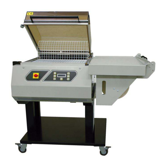
- Page 1 Smipack SL55 Shrink Wrap Machine...
- Page 3 SL series - Use and maintenance manual USE AND MAINTENANCE MANUAL L-seal hood packer SL45 - SL55 MANUAL CODE: DM210649 DATE OF CREATION: 11.04.2012 REVISION: VERSION DATE: 07.03.2016...
- Page 4 This manual can be used for the model SL45 - SL55. It has been drawn up to put you in conditions to be able to intervene on the various parts, and to understand the various maintenance and intervention operations.
-
Page 5: Ce Declaration Of Conformity
(Directive 2006/42/EC - Annex IIA) Company name and address of manufacturer of the machine : SMIPACK S.p.A. - Via Piazzalunga 30, 24015 San Giovanni Bianco (BG) - ITALY Tel. +39 0345 40400 - Fax +39 0345 40409 Name and address of the company authorized to compile the technical documentation : SMIPACK S.p.A. - Page 6 White page...
-
Page 7: Table Of Contents
SL series - Use and maintenance manual SUMMARY CE DECLARATION OF CONFORMITY ..............................5 GENERAL STANDARDS AND RECOMMENDATIONS ......9 HOW TO READ AND USE THE MANUAL ......................9 WARRANTY AND EXCLUSION OF LIABILITY ....................9 REFERENTIAL STANDARDS .........................10 SYMBOLS KEY ...............................10 MACHINE INSTALLATION ...............13 DESCRIPTION OF MACHINE COMPONENTS .....................13 WEIGHT AND DIMENSIONS OF PACKED MACHINE ...................13 MACHINE WEIGHT AND DIMENSIONS ......................14... - Page 8 REPLACING PTFE AND SILICON RUBBER ....................37 MACHINE ACCESS AREAS FOR INSPECTIONS ..................38 ANOMALIES AND FAULTS - HOW TO RESOLVE ........39 SOLUTIONS TO OPERATING PROBLEMS ....................39 ERROR AND MESSAGE DISPLAYS ......................40 END MANUAL ................................44...
-
Page 9: General Standards And Recommendations
(operators and maintenance personnel) so that they may be consulted promptly when circumstances require it. SMIPACK S.p.A. will not be held liable for possible faults, accidents or problems due to failure to comply with the provisions contained in this user manual or caused by unauthorised modifications and installations of accessories. -
Page 10: Referential Standards
365 day validity starting from the date of purchase. During the period covered by warranty, SMIPACK commits itself to remove any faults or defects as long as periodical maintenance is performed and original parts are always used. Expendable materials, parts subject to normal wear or breakage, faults caused by atmospheric agents, transporting the machine to an assistance centre and labour charges are excluded from the warranty. - Page 11 SL series - Use and maintenance manual N.B.! Provides important indications to consult the manual or general warnings. Before operating make sure the indications refer to the machine model you have purchased. WARNING! This indicates situations of risk for the machine and/or for the product being processed.
- Page 12 Chapter 1 - General standards and recommendations USE OF SAFETY FOOTWEAR COMPULSORY USE OF HEARING PROTECTION COMPULSORY USE OF GLOVES COMPULSORY CLOTHING COMPULSORY GOGGLES COMPULSORY...
-
Page 13: Machine Installation
SEALING BLADE PLATE HOOD OUTFEED PRODUCT DOOR POWER BOARD HEAT-SHRINKING FAN HEATING ELEMENTS (OVEN MASTER SWITCH ZONE) OPERATOR PANEL 2.2 WEIGHT AND DIMENSIONS OF PACKED MACHINE SL45 SL55 Fig. 2.2.1 X (mm) 1140 1330 Y (mm) H (mm) WEIGHT (kg) -
Page 14: Machine Weight And Dimensions
*** with machine supports 2.4 TRANSPORTATION AND UNPACKING SMIPACK S.p.A., depending on the type of transportation and products to be delivered, uses adequate packaging to guarantee integrity and preservation during transportation. Handle with care when transporting and positioning the machine. The carrier is liable for damage sustained during transportation. -
Page 15: Mounting Machine Supports
SL series - Use and maintenance manual 2.5 MOUNTING MACHINE SUPPORTS The SL series models can be positioned on specifically designed machine supports available on-demand. Two versions are available: A and B. A: Version with trolley - Mount the machine holding trolley as shown in fig. 2.5.1. - Position the machine on the trolley matching the feet 1 with the specific holes 2 and then use the screws 3 to fasten the trolley to the machine. -
Page 16: Inserting Fuses In The Power Board
Chapter 2 - Machine installation ATTENTION! Make sure to attach the supports A and B in the correct position. Mount the two wheels C equipped with brakes at the front of the machine. Fig. 2.5.5 2.6 INSERTING FUSES IN THE POWER BOARD The machine is delivered with the fuses not yet installed in the fuse-holder. -
Page 17: Electrical Connection
2.8 ELECTRICAL INSTALLATION DATA Install a circuit breaker on the machine power supply line which supports the values indicated in the table. SL45 SL55 Nominal 220÷240 V 220÷240 V voltage... -
Page 18: Demolition And Waste Disposal
Chapter 2 - Machine installation DECLARED NOISE EMISSION VALUES IN COMPLIANCE WITH THE STANDARD ISO 4871 ARE: A-WEIGHTED EMISSION SOUND PRESSURE LEVEL (AT OPERATOR POSITION): 70 dB ATTENTION! The exposure of the operator to noise may also vary due to background noise generated by other equipment present where the machine is installed. -
Page 19: Information On The Machine
SL series - Use and maintenance manual CHAPTER 3 - INFORMATION ON THE MACHINE 3.1 DESCRIPTION OF THE MACHINE The SL series hood packer is equipped with a simple but complete control panel connected to a microprocessor which guarantees high performance and provides the operator with a great deal of autonomy. -
Page 20: Identification Data And Technical Data Of The Machine
Chapter 3 - Information on the machine ATTENTION! Leave the hood open when the machine is switched off to allow it to cool down. Near some zones of the machine, some pictograms were placed in order to recall the attention of the operator concerning the precautions required to avoid dangers. -
Page 21: Technical Specifications Of The Product
Do not wrap anything which is not intended or which can in any way be dangerous for the user and damage the machine. Before performing any modification, you must contact SMIPACK S.p.A for their consent 3.5 FEATURES OF THE FILM The machine has been designed to package various products using PVC e Polyolefin film with a thickness up to 30 µm. -
Page 22: Determination Of Film Width
Chapter 3 - Information on the machine SL45 SL55 450 mm 600 mm Ø250 mm Ø250 mm Ø77 mm Ø77 mm Fig. 3.5.1 WEIGHT 20 kg 20 kg MAXIMUM 3.6 DETERMINATION OF FILM WIDTH To determine the width L of the film reel used for packaging, follow this formula: L reel = Y product + H product + 50 mm Fig. -
Page 23: Film Heat-Shrinking Operation
SL series - Use and maintenance manual 3.8 FILM HEAT-SHRINKING OPERATION Film is shrunk the same time as it is sealed. This is produced by the forced circulation of hot air around the package. The air is heated by means of a group of temperature controlled heating elements. - Page 24 White page...
-
Page 25: Preparing The Machine For Use
SL series - Use and maintenance manual CHAPTER 4 - PREPARING THE MACHINE FOR USE 4.1 POSITIONING REEL AND FILM PASSAGE • Insert the film reel in the reel holder 1 blocking it with the self-centring tapered supports 2. • Pass the film through the perforators 3. •... -
Page 26: Adjusting Height Of Product Support Mesh
Chapter 4 - Preparing the machine for use 4.3 ADJUSTING HEIGHT OF PRODUCT SUPPORT MESH Adjust the height of the product support mesh 1 by means of the striker plates 2 and 3 according to the height of the pack. For best packaging, the film must be sealed at approximately half the height of the product. -
Page 27: Positioning Reel Holder Support And Product Holding Plate
SL series - Use and maintenance manual 4.5 POSITIONING REEL HOLDER SUPPORT AND PRODUCT HOLDING PLATE The reel holder support 1 must be adjusted according to the width L of the product being packaged. Leave approximately 1-2 cm between the product and the sealing edge as shown in the figure. -
Page 28: Packaging Products
Chapter 4 - Preparing the machine for use Help to separate the film with your right hand to keep it from sticking to the sealing blade when cooling after sealing. Fig. 4.6.2 4.7 PACKAGING PRODUCTS After having performed the first film sealing operation, introduce the product to be packaged in the bag, placing it on the specific product support. -
Page 29: Operation And Use
SL series - Use and maintenance manual CHAPTER 5 - OPERATION AND USE 5.1 OPERATOR PANEL INTERFACE KEY FUNCTIONS Switches the machine on and off. Signals correct power supply to the machine with the indicator light on. Selects the sealing program. (in this operating mode the product will be packaged in a slack bag). -
Page 30: Turning The Machine On
Chapter 5 - Operation and use 5.2 TURNING THE MACHINE ON Turn the master switch on the operator panel to ON. The display will visualise the machine model and software version for a few seconds, followed by the last working mode memorised (sealing or heat shrinking), the active memory and the number of packs wrapped. -
Page 31: Saving A Program
SL series - Use and maintenance manual and the LED of the key flashes, only the sealing process can be performed. This machine status will be maintained until the heating elements reach the temperature set in the “parameters menu”. 5.4 SAVING A PROGRAM Depending on the size of the product and the type of film you wish to use, some operating parameters must be set in order to guarantee quality packaging. - Page 32 Chapter 5 - Operation and use 2 • Tunnel temperature Menu for adjusting tunnel temperature. Fig. 5.5.2 Tunnel (can be set from 1 to 10) Temperature 3 • Shrinking Timer Menu for adjusting heat shrinking time. Fig. 5.5.3 Shrinking (can be set from 1 to 10) Time 4 •...
-
Page 33: Access To Reserved Menu
SL series - Use and maintenance manual 5.6 ACCESS TO RESERVED MENU Press simultaneously to access the reserved menu with the adjustment parameters calibrated when the machine was test inspected. Fig. 5.6.1 Insert Password ***** Use the password PROGR to access the selection of parameters normally adjusted at machine inspection. - Page 34 Chapter 5 - Operation and use Indicates a heat shrinking process in progress. Indicates that the fan for the heat shrinking process is active.
-
Page 35: Cleaning And Maintenance
SL series - Use and maintenance manual CHAPTER 6 - CLEANING AND MAINTENANCE 6.1 GENERAL WARNINGS AND PRECAUTIONS Before starting any of the maintenance operations described in this chapter, switch the machine off and disconnect it from the power mains. 6.2 NATURE AND FREQUENCY OF MAINTENANCE CHECKS AND INTERVENTIONS In the manual, the description of the various maintenance operations is often associated to the... -
Page 36: Replacing Sealing Blade
Chapter 6 - Cleaning and maintenance Tab. 6.2.1 - Interventions on mechanical components Operations Symbol Frequency of Machine device to be carried out used intervention Remain film residue stuck to sealing blade. Clean the sealing blade with a 12 hours moist cloth wearing protective gloves to avoid cuts and/or burns. -
Page 37: Replacing Ptfe And Silicon Rubber
SL series - Use and maintenance manual Fig. 6.3.1 6.4 REPLACING PTFE AND SILICON RUBBER If only the PTFE needs to be replaced, proceed as follows: • Remove the worn PTFE 1. • Thoroughly clean the silicon rubber with detergent. •... -
Page 38: Machine Access Areas For Inspections
Chapter 6 - Cleaning and maintenance Replacing silicon rubber • Remove the worn silicon rubber 2. • Thoroughly clean the housing seat of the silicon rubber. • Apply a few drops of glue or else two-sided adhesive tape on the side of the silicon rubber to be glued at the bottom of the conduit. -
Page 39: Anomalies And Faults - How To Resolve
SL series - Use and maintenance manual CHAPTER 7 - ANOMALIES AND FAULTS - HOW TO RESOLVE 7.1 SOLUTIONS TO OPERATING PROBLEMS The following table describes the solutions to the most common problems which can occur while the machine is operating. PROBLEM CAUSE SOLUTION... -
Page 40: Error And Message Displays
Chapter 7 - Anomalies and faults - how to resolve 7.2 ERROR AND MESSAGE DISPLAYS This paragraph describes the messages and errors that can be viewed on the display of the operator panel with the relative solutions. These messages can be accompanied by an acoustic signal. - Page 41 SL series - Use and maintenance manual PROBLEM CAUSE SOLUTION Disconnect the power cable and perform the following controls: check the proper connection of the heating elements to the circuit board; check functioning of the circuit court heat shrinking ERROR 4 temperature increases Attention - at times the error can be...
- Page 42 Chapter 7 - Anomalies and faults - how to resolve PROBLEM CAUSE SOLUTION Disconnect the power cable and perform the following controls: check the electromagnet and make sure the connection cables are intact. ERROR 10 24V outputs overcurrent error. If the problem continues, interrupt sealing or heat shrinking operations, disconnect power cable...
-
Page 44: End Manual
SMIPACK does not assume any responsibility for the improper use of the machine. SMIPACK reserves the right to carry out technical modifications on its systems and on this manual without prior notice. END MANUAL...
Need help?
Do you have a question about the SL55 and is the answer not in the manual?
Questions and answers