Table of Contents
Advertisement
Advertisement
Table of Contents

Related Manuals for Smipack BP700AR/310


Summary of Contents for Smipack BP700AR/310
- Page 3 Use and maintenance manual BP700AR/310 USE AND MAINTENANCE MANUAL Film shrink-wrapping machine with sealing bar ßP700AR/310 MANUAL CODE DM210190 CREATION DATE 14.04.2005 RELEASE: RELEASE DATE: 17.04.2007 3 / 58...
- Page 4 FOREWORD In thanking you for the preference given us, SMIPACK S.p.A. is glad to welcome you to its wide circle of Clients and hopes that the use of this machine completely satisfies you. IThis manual can be used for model ßP700AR/310 and was prepared with the aim to allow you to operate on the various components, explain the various operations for maintenance and operation.
-
Page 5: Dichiarazione Di Conformità Ce
Il fabbricante SMIPACK S.p.A., con insediamenti produttivi e uffici amministrativi-direzionali in Viale Vittorio Veneto, 4 24016 S.Pellegrino Terme (BG) - ITALIA The company SMIPACK S.p.A., with production site and head-quarters in Viale Vittorio Veneto, 4 24016 S.Pellegrino Terme (BG) - ITALY... - Page 6 e alle norme armonizzate di buona pratica costruttiva, tra cui: and with Harmonized Standards: Macchine per gomma e materie plastiche - Sicurezza - Macchine per soffiaggio per la produzione di corpi cavi - Requisiti per la progettazione e costruzione. EN 422 Safety of rubber and plastics machines - Blow moulding machines intend- ed for the production of hollow articles - Requirements for design and con- struction...
-
Page 7: Table Of Contents
Use and maintenance manual BP700AR/310 SUMMARY Dichiarazione di conformità CE ......................... 5 EC Declaration of conformity ........................5 REGULATIONS AND GENERAL INSTRUCTIONS ......9 1.1. HOW TO CONSULT AND USE THIS MANUAL ................. 9 1.2. WARRANTY CONDITIONS ........................ 9 1.3. LEGAL REFERENCES ........................9 1.4. - Page 8 ADJUSTMENTS AND SETTINGS ............25 5.1. MACHINE OPERATION AND GUIDE ALIGNMENT ................ 25 5.2. FEEDING BAR ADJUSTMENT ......................25 5.3. ADJUSTING THE FILM WINDING ROLLER ..................26 5.4. ADJUSTING THE FILM TENSION ....................26 5.5. ADJUSTING THE INFEED PRESS ....................27 5.6.
-
Page 9: Regulations And General Instructions
The descriptions and drawings contained in the present manual are intended as non refutative. SMIPACK S.p.A. reserves the right at any moment to apport modifications to its machines (while keeping their essential characteristics), for the purpose of improving their functionality and commercial and aestethic value, with no obligation to update manuals and previous production except in exceptional cases. -
Page 10: Remarks On General Safety
Do not install the machine in areas posing a risk of explosion or fire. • Do not temper with, remove or modify the safety devices; in such cases SMIPACK S.p.A. declines any responsibility on the safety of its machines. •... -
Page 11: Symbol Legend
Use and maintenance manual BP700AR/310 ATTENTION! The operator, the maintenance and cleaning personnel must scrupulously adhere to both the regulations for the prevention of accidents and the safety regulations of the Country of destination of the machine and the plant, besides the instructions, warnings and general rules concerning the safety included in this manual. -
Page 12: Machine Installation
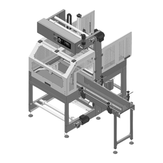
2. MACHINE INSTALLATION 2.1 DESCRIPTION OF THE MACHINE Fig. 2.1.1 GLOSSARY Feeding bar Sealing blade Reel holder Tensioning bars Electronic card Connecting belt Infeed belt 90° 2.2 WEIGHT AND DIMENSIONS OF THE PACKED MACHINE Fig. 2.2.1 ßP700AR/310 ßP700AR/310 in phenolic wood box 1685 1715... -
Page 13: Weight And Dimensions Of The Machine
WEIGHT Kg 375 2.4 TRANSPORT AND UNPACKING SMIPACK S.p.A. in function of the means of transport and of the type of products to be shipped utilizes pac It is recommended to handle with great care the machine during transport and positioning. -
Page 14: Positioning And Levelling
2.5 POSITIONING AND LEVELLING Fig. 2.5.1 Make sure that the floor, in the installation area, does not present irregularities that may prevent the normal and correct positioning of the machine. After placing a level on the upper part of the frame, level the machine using the adjustable support feet then lock them by tightening the locknuts. -
Page 15: Technical Data For The Electric Connection
Use and maintenance manual BP700AR/310 Earthening is compulsory! The machine's connection to the mains must be carried out in thorough compliance with the regulations of the user's country. Make sure that the frequency and voltage of the machine's power supply (as indicated on the nameplate to be found on the rear of the machine) correspond to the mains'. -
Page 16: Machine Identification
Modify the electrical connections to by-pass the internal safeties; • Remove the protections installed Before performing any modification it is necessary to contact SMIPACK S.p.A to obtain the relevant authorization. ATTENTION! It is not possible to pack anything that can in any way be dangerous to the user and damage the machine itself. -
Page 17: Shrink-Wrapping Film Characteristics
Use and maintenance manual BP700AR/310 3.6 SHRINK-WRAPPING FILM CHARACTERISTICS Fig. 3.6.1 The machine has been designed to obtain the packaging of the most diversified products, using a shrink-wrapping film thickness of 40 and 100 µm. 3.7 DANGEROUS AREAS • Do not touch the sealing bar immediately after a sealing going beyond the protection barrier. -
Page 18: First Film Sealing
2 • Wrapping and film sealing section: • Check the film tension. • Check that there are no breakings on the sealing bar. • Test the blade and check if there are broken or folded teeth (be very careful when working near the blade, use protection gloves when handling ). -
Page 19: Choosing The Operating Mode
Use and maintenance manual BP700AR/310 Fig. 4.1.1 ATTENTION! Before operating make sure that the temperature of the sealing bar is the one that has been set. 4.2 CHOOSING THE OPERATING MODE The film shrink-wrapping machine can operate through three different modes: manual, semiautomatic and automatic. -
Page 20: Automatic Selection
4.5 AUTOMATIC SELECTION Press [F3] and the following mode selection video page will appear on the display: Press the push button [-] to position on the selection AUTO and press [POWER] to confirm and then [ENTER] to go back to the main video page. The push button [F1] is the start push button. - Page 21 Use and maintenance manual BP700AR/310 2 • Pack loading Menu to adjust the pack loading time into the pushing device (Value 0-10). The loading time depends on the speed set on the input belt and on the distance which creates between the pack (placed on the pushing device at the middle of the machine) and the photocell.
- Page 22 5 • Sealing timer Menu that sets the sealing time of the sealing bar (Value 0-10). Fig. 4.8.5 Using the keys [+] and [-] you increase or decrease the value of a unit. 6 • Bar temperature Menu that sets the sealing temperature (value 50°C-160°C; increase 1°C). Fig.
-
Page 23: Parameters Menu (F3+)
Use and maintenance manual BP700AR/310 4.9 PARAMETERS MENU (F3+) Press the keys [F3] and [+] simultaneously and you access to the menu that contains the parameters: 1 • Language Menu that sets the language: Fig. 4.9.1 Set the language with the keys [+] and [-]. -
Page 24: Symbols And Display Messages Legend
Activate with the keys [+] and [-] 0 = Inactive 1 = Active 5 • Pack approaching When it is set: Value 1) While a product is under process, the belt movement continues Value 0). While a product is under process, the belt stops at the input Fig. -
Page 25: Adjustments And Settings
Use and maintenance manual BP700AR/310 5. ADJUSTMENTS AND SETTINGS 5.1 MACHINE OPERATION AND GUIDE ALIGNMENT The machine has been designed to package products by "steps" without grouping/making up of the pack. The machine can package according the two modes shown in fig. 5.1.1 and Fig. -
Page 26: Adjusting The Film Winding Roller
Fig. 5.2.2 3 • By acting on the handles 3 the rods 5 can be shifted. By slackening the screws 4 it is possible to shift the stopping devices in accordance with the depth of the product to be packaged and then to unthread one of the two supports 1.The pack shall not be protude more than 1 or 2 cm with respect to the stopping... -
Page 27: Adjusting The Infeed Press
Use and maintenance manual BP700AR/310 ATTENTION! A wrong adjustment of the counterweights could cause the following problems: • The film does not flow on the tensioning bars and the product tips over. • The film, being statically loaded, sticks to the reel. - Page 28 Fig. 5.7.1 28 / 58...
-
Page 29: Maintenance And Repairs
Use and maintenance manual BP700AR/310 6. MAINTENANCE AND REPAIRS ATTENTION! Before begining any type of maintenance operation indicated in this chapter, unless otherwise required, switch off the machine, switch voltage off acting on the main switch, pull out the power supply cable from the mains and disconnect the tube that feeds the pneumatic plant. - Page 30 Tab. 6.1.3 MONTHLY MAINTENANCE CHART (240 HOURS OF WORKING) SEALING UNIT MAKE SURE THAT THERE ARE NO BREAKAGE ON THE CUTTING BLADE CHECK THE WEARING STATE OF THE SILICON RUBBER CLEAN AND GREASE THE GUIDES MAKE SURE THAT THE PNEUMATIC PARTS ARE WORKING CORRECTLY PROTECTIONS CLEAN THE SWITCHES AND THE EMERGENCY SAFETIES CONVEYOR BELT UNIT...
-
Page 31: Cleaning And Checking The Sealing Group
Use and maintenance manual BP700AR/310 Among the maintenance checks and operations of general nature there are: • Lubrication • Cleaning • Checks of the warning and signalling devices • Checks of safety and emergency devices 6.2 CLEANING AND CHECKING THE SEALING GROUP Fig. -
Page 32: Replacing Silicone Rubber And Springs Of The Sealing Contrast Unit
• Then, after unscrewing the screws 3 Fig. 6.3.2 and 4, separate the two elements 5 as in fig. 6.3.2 • Replace blade using protection gloves ATTENTION! The blade must be positioned so that it combines perfectly with the sealing unit. A wrong positioning could break the sealing unit and the blade. -
Page 33: Replacing The Components Of The Sealing Bar
Use and maintenance manual BP700AR/310 6.5 REPLACING THE COMPONENTS OF THE SEALING BAR • To replace the pieces of the sealing bar operate as follows: • Disconnect all the wires resistor unscrew the nuts 1 of the photoelectric cells. •... -
Page 34: List Of Spare Parts
6.6 LIST OF SPARE PARTS The following lists illustrate the electrical and mechanical components (divided in groups ). For a fast dispatch of the order we recommend to supply all the requested information. 1 • Unit MH230000 Pos. Description spare parts Code Pos. -
Page 35: Gruppo Mh250003
Use and maintenance manual BP700AR/310 2 • Unit MH250003 Pos. Description spare parts Code Pos. Description spare parts Code ROUND BAR MA108209 HEATING ELEMENT MA108202 SENSOR EF100073 SUPPORT MA227360 BEARING MF801068 THERMOCOUPLE EE400013 SPRING MA901575 PLATE MA225547 35 / 58... -
Page 36: Gruppo Mh250002
3 • Unit MH250002 Pos. Description spare parts Code Pos. Description spare parts Code SEALING GROUP MH250002 36 / 58... -
Page 37: Gruppo Mh250004
Use and maintenance manual BP700AR/310 4 • Unit MH250004 Pos. Description spare parts Code Pos. Description spare parts Code BUSH MF800243 SPRING MF100369 FLAT BAR MA217961 FLAT BAR MA225579 SECTION BAR MP400327 m. 1,5 ROLLER MF500481 BLADE MA217968 37 / 58... -
Page 38: Gruppo My330004
5 • Unit MY330004 Pos. Description spare parts Code Pos. Description spare parts Code SHAFT MA107519 MA107877 SHOCK ABSORBER MF900668 MA108369 MA110068 HANDLE MF900857 BEARING MF800290 JOINT HEAD MF600066 38 / 58... -
Page 39: Gruppo My340035
Use and maintenance manual BP700AR/310 6 • Unit MY340035 Pos. Description spare parts Code Pos. Description spare parts Code ROLLER MH200036 PLATE MA201359 RUBBER ROLLER MA700989 COGGED BELT MF500435 ROLLER MH200035 GEAR BOX EM650231 SPRING MF100440 MOTOR EM600174 MN300113 ROLLER... -
Page 40: Gruppo My380001
7 • Unit MY380001 Pos. Description spare parts Code Pos. Description spare parts Code TEFLON MA107707 RUBBER ROLLER MA701003 MOTOR EM600175 ROLLER MF500399 GEAR BOX EM650197 GEAR BOX EM650205 SHAFT MA108867 40 / 58... -
Page 41: Gruppo Mh220001
Use and maintenance manual BP700AR/310 8 • Unit MH220001 41 / 58... -
Page 42: Gruppo Mh220002
9 • Unit MH220002 Pos. Description spare parts Code Pos. Description spare parts Code CABLE EC100086 SUPPORT MN010193 CONNECTION MN300091 CABLE EC100107 DETAILS GROUP MG490144 CONNECTION MN300062 SENSOR MN400100 CYLINDER MN010119 CABLE EC100108 CONNECTION MN300078 42 / 58... -
Page 43: Gruppo Mh220003
Use and maintenance manual BP700AR/310 10 • Unit MH220003 Pos. Description spare parts Code Pos. Description spare parts Code CABLE EC100086 CONNECTION MN300062 CABLE EC100107 CONNECTION MN300078 JOINT HEAD MF900909 CONNECTION MN300091 DETAILS GROUP MG490144 SENSOR MN400100 SUPPORT SENSOR MN010105... -
Page 44: Gruppo Mg490144
11 • Unit MG490144 Pos. Description spare parts Code Pos. Description spare parts Code SILENCER MN300475 MN300883 CONNECTION MN300063 ELECTROVALVE MN400051 CONNECTION MN300495 44 / 58... -
Page 45: Gruppo My390003
Use and maintenance manual BP700AR/310 12 • Unit MY390003 Pos. Description spare parts Code Pos. Description spare parts Code ROLLER MH200058 ROLLER MH200059 MA107523 SPRING MF100255 BUSH MF800309 MA107521 ROLLER MH200060 LIMIT SWITCH EF010052 45 / 58... -
Page 46: Gruppo Mh220004
13 • Unit MH220004 Pos. Description spare parts Code Pos. Description spare parts Code CONNECTION MN300063 CABLE EC100086 DETAILS GROUP MG490144 CYLINDER MN010136 CONNECTION MN300538 CONNECTION MN300078 46 / 58... -
Page 47: Gruppo My340036
Use and maintenance manual BP700AR/310 14 • Unit MY340036 Pos. Description spare parts Code Pos. Description spare parts Code MOTOR EM600175 BEARING MF800291 GEAR BOX EM650243 SUPPORT MF800292 DRAGGING WHEEL MF400638 PHOTOCELL GROUP MH280000 TAPE MF500638 47 / 58... -
Page 48: Gruppo My350012
15 • Unit MY350012 48 / 58... -
Page 49: Gruppo My350011-1
16 • Unit MY350011-1... -
Page 50: Gruppo My350011-2
17 • Unit MY350011-2... -
Page 51: Gruppo My350011-3
18 • Unit MY350011-3... -
Page 52: Gruppo My350011-4
19 • Unit MY350011-4... -
Page 53: Gruppo My350011-5
20 • Unit MY350011-5... -
Page 54: Integration To The Manual
6.7 INTEGRATION TO THE MANUAL The machine is fitted with an inverter (Fig.6.7.1) which can increase or decrease the input conveyor belt Fig. 6.7.1 speed at 90°. A reduced speed of the conveyor belt will bring about an increase in the product stability and a speed increase will produce better performances. -
Page 55: Anomalies And Failures - How To Remedy
Use and maintenance manual BP700AR/310 7. ANOMALIES AND FAILURES - HOW TO REMEDY POSSIBLE CAUSES AND REMEDIES Following, the descriptions and relative solutions of common problems that could occur during the normal operation of the machine. ATTENTION! All the checking and replacing operations on the machine, must be carried out without voltage. - Page 56 PROBLEM 1: Cooling fin overtemperature Solution: • Check the board heatsink cooling fan • Check that the electrical panel air intakes are not obstructed • If the problem continues, switch power off and contact the service centre. PROBLEM 2: Temperature reading outside the set limits. Solution: •...
- Page 57 Use and maintenance manual BP700AR/310 PROBLEM 11: Wrong thermocouple temperature reading. Solution: • Check probe • Check probe cable connection • Check earthing connection • If the problem continues, switch power off and contact the service centre. PROBLEM 12: Bar temperature over the permitted value.
- Page 58 SMIPACK S.p.A. is absolutely not responsible for any direct or indirect consequences due to the proper or improper use of this issuing of the system software. SMIPACK S.p.A. has the right to make technical modification on their system and in their manual without informing the users.
Need help?
Do you have a question about the BP700AR/310 and is the answer not in the manual?
Questions and answers