Table of Contents
Advertisement
Quick Links
Advertisement
Table of Contents

Subscribe to Our Youtube Channel
Related Manuals for Wisenet XRP-4310DB4


Summary of Contents for Wisenet XRP-4310DB4
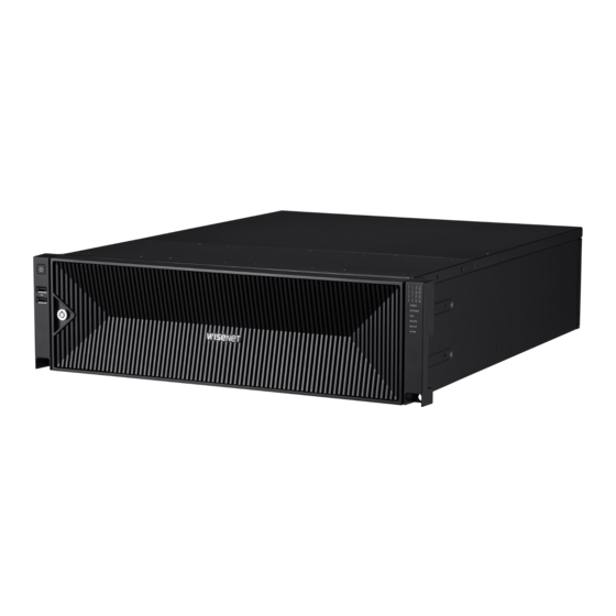
- Page 1 Server Network video recorder Quick Guide XRP-4310DB4 XRP-4210B4...
- Page 2 Server Network Video Recorder Quick Guide Copyright ©2020 Co., Ltd. All rights reserved. Hanwha Techwin Trademark Each of trademarks herein is registered. The name of this product and other trademarks mentioned in this manual are the registered trademark of their respective company. Restriction Copyright of this document is reserved.
-
Page 3: Table Of Contents
table of contents Before Reading the User Manual overview Inspecting Installation Environment Composition of User Manual and Guidelines Checking Components Name and Function of Each Part 12 Cautions when installing a HDD iNStalliNg the hdd 13 Installing the HDD 15 Rack installation requirements and reference iNStalliNg the rack dimensions 17 Precautions when selecting shelves... - Page 4 overview overview Before reading the User ManUal Make sure to check the contents below before reading the User Manual. • The copyright of this User Manual is held by the manufacturer. • This User Manual cannot be reproduced without prior approval. • The manufacturer is not responsible for any damage resulting from the use of non-standardized products or for the use of purposes other than those stated in the User Manual.
- Page 5 inspecting installation environMent This product is a top-notch security device that is equipped with a high-capacity HDD and other key circuit boards. Note that an excessive internal temperature of the product may cause a system failure or a shortened product life. Keep in mind the following instructions before installing the product. When mounting the product on a rack, comply with the following instructions.
- Page 6 overview coMposition of User ManUal and gUidelines This User Manual is composed as follows. • Quick Guide • SSM User Manual • Supplementary Manual to Link with Other Systems • RAID Manual (English) The User Manual is in a PDF file format. The manual can be read by downloading and installing a free PDF viewer on the Internet.
- Page 7 Server NVR Mouse Quick Guide Power Cable (2 ea) Power Cable (1 ea) Front Cover Lock Key (XRP-4310DB4) (XRP-4210B4) HDD Fixing Screw Anti-slip Rubber Pad Hard Disk Number Sticker Components may look different compared to the image. The type and quantity of components may differ depending on the model.
- Page 8 overview naMe and fUnction of each part NamE aNd FuNctioN oF thE FroNt PaNEl name function description Power It is used to turn on the power. A security device to restrict access to the hard disk. Hard disk door lock key Use the key provided from purchase of product.
- Page 9 LED will light up when the recorded video is being exported. alarM: LED will light up in case of fan, RAID, or redundant power (XRP-4310DB4) failure. You can check the operation status of each hard disk by opening the front cover of the recorder.
- Page 10 NamE aNd FuNctioN oF thE rEar PaNEl XrP-4310dB4 XrP-4210B4 10_ overview...
- Page 11 A terminal to connect to power. (XRP-4310DB4) • Although the product will function normally even when only one power is connected due to power redundancy, it is recommended Power that each power is connected to separate sources for stability.
- Page 12 installing the HDD installing the HDD Make sure to unplug the power cord from the wall outlet to prevent possible electric shock, injury or product damage. Please consult your provider for further information on HDD installation since improper installation or settings may damage the product.
- Page 13 installing the hdd 1. Use the front cover lock key to unlock the cover. Grab the front cover with both hands and pull it to the left to remove it. 2. Press the orange button on the hard disk bracket to the left and pull forward to separate the main body and the hard disk bracket.
- Page 14 installing the HDD 4. Once the HDD is mounted in the bracket, push the bracket into the main body and close the front cover. • Fit the front cover into the right notch of the main body, then press and close until you hear a 'click'. • Use the front cover lock key to lock the front cover so that it does not get separated.
-
Page 15: Rack Installation Requirements And Reference Dimensions
installing the rack rack installation reqUireMents and reference diMensions classification requirements Rack type 19-inch rack of EIA-310-D standard POST count POST distance Depth 800 mm dimENsioNs oF mouNtiNG FlaNGE Product EIA-310-D standard mounting flange Product Product Notable dimensions index dimension 450 mm (17.717 inches) min. - Page 16 installing the rack flange mounting holes EIA-310-D The standard mounting flange is composed of circular, square, and screw fastening holes. Square mounting holes 15.90 mm (0.625 inches) 15.90 mm (0.625 inches) 44.45 mm (1.750 inches) 12.7 mm (0.50 inches) 15.90 mm (0.625 inches) 15.90 mm (0.625 inches) 9.5 mm (0.375 inches) Square 12.7 mm (0.50 inches)
-
Page 17: Precautions When Selecting Shelves
precaUtions when selecting shelves To prevent any problem while installing the recorder, make sure to select a structure where the bottom of the product is mounted. For installation stability, fixed shelf dedicated to 19-inch rack that supports the load of at least 30 kg is recommended. -
Page 18: Precautions When Using Sliding Shelves
installing the rack precaUtions when Using sliding shelves When removing a shelf, fix the rack to the ground Avoid leaning on the installed product or place an so that it does not get toppled. object on it while its shelf is pulled out. When sliding in/out the shelf, be careful not to Use a shelf that supports the load of at least drop the product. -
Page 19: How To Install Rack
how to install rack 1. Mount the fixed or sliding shelf onto the 19-inch rack. See the manual provided by the manufacturer for installing the fixed shelf. 2. Place the recorder on the shelf and push it until the left/right fixing holes of the recorder align with the mounting flange holes of the 19-inch rack. -
Page 20: Power
running the product running the product power Connect the power cord to the back of the product and press the power button. If the power does not turn on, check the following items. Check that the power cable is properly connected and that it meets the power specifications. When using a multi-tab, check that the power of the multi-tab is turned on. -
Page 21: Setting Windows Password
setting windows password This section will explain how to set the Windows password. This product does not have a preset Windows password. Make sure to set the password for secure use. Safely store the Windows user name and password so that it is not forgotten. Change the password every 3 months for security. - Page 22 In "Sign-in Options", select "Add" under "Password". In "Create a password", create a new password. When the settings are complete, restart the PC and check that the new password has been applied. 22_ running the product...
-
Page 23: Windows Auto Sign-In Settings
windows aUto sign-in settings This section will explain the method of setting Windows auto sign-in during product startup. The use of Windows auto sign-in is not recommended due to its vulnerability in security. After setting this feature, safely store the Windows user name and password so that it is not forgotten. how to sEt wiNdows Password Press Windows key + R and enter netplwiz in the Run window. - Page 24 running the product Click "Apply" then "OK". Enter the user name and password and click "Apply". When the settings are complete, restart the PC and check that the auto sign-in works. 24_ running the product...
-
Page 25: Creating A Logical Drive
creating a logical drive This section will explain how to configure a logical drive. Use a new disk for RAID configuration or replacement of a faulty disk. Double click the SSM Service Manager icon on the Desktop to run. After clicking the "Stop Service" button, check that the service status is Stopped. If the service status is Running, select Stopped. - Page 26 running the product Enter the user name and password. Use the Windows user name and password. The default product User name is "Administrator" and there is no password. Check the number of mounted disks and their status in Physical Devices. (Status is Unconfigured) Click Adapter, and when the sub menu appears after positioning the mouse over Operation, select Create Array.
- Page 27 Select disk image for RAID configuration. (A tick will appear to the right of the selected disk.) When using RAID 5 or RAID 6, less than a maximum of 8 disks per Array is recommended for optimal product performance. Use the ID below the disk image to check the location in the HDD ID Mapper. Run by clicking the HDD ID Mapper icon on the Desktop.
- Page 28 running the product 10. Select the RAID Level and Stripe Size and click Submit. RAID 5 is recommended for optimal product performance. Select 256K Stripe Size for optimal product performance. Select Enable for Disk Cache for optimal product performance. Playback is restricted to a maximum of 50 Mbps and 32 channels for RAID rebuild. There may be a decrease in backup performance for RAID rebuild.
- Page 29 12. Select Virtual Disk under Array to check information. (Status is Functional) 13. In Windows Disk Management, check the disks configured for RAID. It is recommended to complete the Virtual Disk configuration for all disks being used before checking. Disks that have not been configured for Virtual Disk will also be displayed in the Disk Management screen.
- Page 30 running the product If the Initialize Disk screen does not appear, right-click on the Disk 1 area and select Initialize Disk. 15. Right-click on the Unallocated area and select New Simple Volume. 30_ running the product...
- Page 31 16. Click Next in the New Simple Volume Wizard. After checking the Simple Volume Size, click Next. The Simple Volume Size may differ depending on the HDD capacity and RAID Level. English _31...
- Page 32 running the product 18. After checking the drive letter, click Next. 19. After changing the allocation unit size to 256K, click Next. Select 256K for the allocation unit size for optimal product performance. 32_ running the product...
- Page 33 20. Click Finish to complete the New Simple Volume Wizard. 21. Check that the disk is recognized normally. English _33...
-
Page 34: Create Network Teaming
running the product create network teaMing This section will explain how to configure Teaming to create network redundancy. The Teaming feature must be used with the switches below. A. Cisco GEC support switch using PAgP protocol B. Intel Link Aggregation support switch C. - Page 35 Select Realtek PCIe GbE Family Controller. Select Teaming category. Click Create Team Category. English _35...
- Page 36 running the product Set as shown below and select OK. a. Enter the team name to use in the Team Name Category. Select either Fast/Giga EtherChannel or Link Aggregation option according to use. c. Select both of the two adapters. Check that the Team has been configured.
- Page 37 Use by setting the IP of the Realtek Virtual Teaming Adapter. English _37...
-
Page 38: Starting Ssm
After selecting "Automatically Run SSM Service on Windows Startup", click Apply. Double click the SSM Console Icon on the Desktop to run the program. Or select [Start] ; Wisenet ; SSM Console. Click Login at the sign-in screen. Enter the default password in the Create Default Password window and click Apply. -
Page 39: Menu Introduction
MenU introdUction The menu of the SSM Console Client is composed of tabs. The desired menu category can be selected by freely moving between tabs. To open a menu page, click "+" at the top left of the program and select the desired menu. The feature of each menu is as follows. - Page 40 running the product By linking with ANPR camera, you can monitor videos in real time, and search or play any videos as you like. Also, you can register/ delete vehicles, edit the registered vehicle information, and check the ANPR management history per vehicle. • ANPR menu is available for use after registering your ANPR license.
- Page 41 You can check the performance of a computer that SSM Console Client is installed. Operate below 60 - 70% CPU usage. Depending on operating conditions, CPU usage may differ to that displayed in the Task Manager. • CPU usage: Displays the CPU usage of the current PC. • Memory usage: Displays the memory usage of the current PC.
- Page 42 MeMo...
- Page 43 MeMo...
- Page 44 Head Office 6, Pangyo-ro 319 beon-gil, Bundang-gu, Seongnam-si, Gyeonggi-do, 463-400 Rep. of KOREA Tel : +82.70.7147.8753 Fax : +82.31.8018.3740 www.hanwha-security.com Hanwha Techwin America 500 Frank W. Burr Blvd. Suite 43 Teaneck, NJ 07666 Toll Free : +1.877.213.1222 Direct : +1.201.325.6920 Fax : +1.201.373.0124 www.hanwhasecurity.com Hanwha Techwin Europe...
Need help?
Do you have a question about the XRP-4310DB4 and is the answer not in the manual?
Questions and answers