Table of Contents
Advertisement
Quick Links
PRODUCT LITERATURE
Lennox Industries Inc.
Dallas, Texas
This boiler cannot be used with all types
of chimneys. Read these instructions
carefully before installing.
INSTALLATION
INSTRUCTIONS
GWB9-050IH-2
GWB9-075IH-2
GWB9-100IH-2
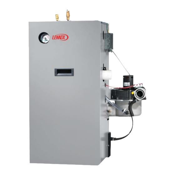
GAS-FIRED, DIRECT VENT,
CONDENSING, HOT WATER BOILER
RETAIN THESE INSTRUCTIONS FOR
FUTURE REFERENCE
These instructions must be affi xed on or
adjacent to the boiler.
WARNING
!
Improper installation, adjustment,
alteration, service, or maintenance
could result in death or serious injury.
Refer to this manual for assistance. For
additional information consult a qualifi ed
installer, service agency, or the gas
supplier.
GAS-FIRED HOT WATER BOILERS
These low pressure gas fi red hot water boilers
are design certifi ed by CSA (Canadian Standards
Association) for use with natural and propane
gases (100 MBH model is certifi ed for natural gas
only). They are constructed and hydrostatically
tested for a maximum working pressure of 50
psi (pounds per square inch) in accordance
with A.S.M.E. (American Society of Mechanical
Engineers) Boiler and Pressure Vessel Code
Section IV Standards for Heating Boilers.
P/N# 240009449, Rev. A [07/2012]
Advertisement
Table of Contents

Related Manuals for Dunkirk GWB9-050IH-2


Summary of Contents for Dunkirk GWB9-050IH-2
- Page 1 INSTALLATION INSTRUCTIONS PRODUCT LITERATURE Lennox Industries Inc. GWB9-050IH-2 Dallas, Texas GWB9-075IH-2 GWB9-100IH-2 GAS-FIRED, DIRECT VENT, CONDENSING, HOT WATER BOILER RETAIN THESE INSTRUCTIONS FOR FUTURE REFERENCE These instructions must be affi xed on or adjacent to the boiler. WARNING Improper installation, adjustment, alteration, service, or maintenance could result in death or serious injury.
-
Page 2: Dimensions
DIMENSIONS Figure 1 - Boiler Dimensions... -
Page 3: Table Of Contents
INTRODUCTION Dimensions ........................2 Introduction ........................3 Important Safety Information ................... 4 Boiler Ratings & Capacities ....................5 Boilers For Use At High Altitude ..................5 Before Installing The Boiler ....................8 Boiler Installation ......................9 Near Boiler Piping ......................11 Combustion Air And Vent Pipe .................. -
Page 4: Important Safety Information
IMPORTANT SAFETY INFORMATION General Installation shall conform to requirements of author- ity having jurisdiction or in absence of such require- Boiler installation shall be completed by qualifi ed agency. ments: See glossary for additional information. • United States WARNING • National Fuel Gas Code, ANSI Z223.1/NFPA 54. Fire, explosion, asphyxiation and electrical shock •... -
Page 5: Boiler Ratings & Capacities
BOILER RATINGS & CAPACITIES Table 1 - SEA LEVEL RATINGS – NATURAL AND PROPANE GASES Input ++ Heating Capacity Net AHRI Rating Shipping Model Flue Diameter *(MBH) *(MBH) Weight (lbs.) *(MBH) 90-50 2” CPVC & PVC 90-75 2” CPVC & PVC 90-100** 2”... - Page 6 BOILERS FOR USE AT HIGH ALTITUDE - UNITED STATES INSTALLATIONS • Boilers (with exception of 90-75 propane (LP) product) • Instructions on how to adjust gas manifold pressure are factory equipped for operation at altitudes ranging settings see Figure 27 and Figure 28, Page 44 . from 0-10,000 feet above sea level.
- Page 7 BOILERS FOR USE AT HIGH ALTITUDE - UNITED STATES INSTALLATIONS Model 90-75 propane (LP) units only at altitudes above 5,000 ft., install 90-75 High Altitude Orifi ce Kit #550002629*. For all other altitudes use sea level orifi ce Table 3 - 90 - 50/75 SERIES 2 PROPANE GAS MODEL 90-50 Stock Factory Btu Value of Propane Gas++...
-
Page 8: Before Installing The Boiler
BEFORE INSTALLING THE BOILER Boiler is equipped for residential installations. If used Boiler Sizing for commercial applications, any additional code Check to be sure you have selected boiler with proper requirements must be adhered to for installation. This capacity before starting installation. AHRI Rating of boiler may require additional controls including but not limited selected should be greater than or equal to calculated to a low water cut off, a manual reset high temperature... -
Page 9: Boiler Installation
BOILER INSTALLATION Locating The Boiler • When vent pipe is exposed to temperatures below freezing, such as when it passes through an unheated Place crated boiler as close to selected location as space or when chimney is used as a raceway, vent pipe possible and un-crate boiler. - Page 10 BOILER INSTALLATION Condensate Drain Requirements In-so-far as is practical, close all building doors and windows and all doors between the space in which the • Pitch condensate drain line down to fl oor drain at mini- appliances remaining connected to the common venting mum of ¼”...
-
Page 11: Near Boiler Piping
NEAR BOILER PIPING Clean the System First Supply And Return Lines Before connecting boiler to heating system, clean and fl ush • Boiler is set up to receive 1 ¼” NPT supply and return system thoroughly. Verify system is free of sediment, fl ux piping from top access. - Page 12 NEAR BOILER PIPING Figure 2 - Single Zone Boiler Piping...
- Page 13 NEAR BOILER PIPING Multi-Zone Systems Multi-zone systems with two zones are typically piped as shown in fi gures 3 or 4. Multi-zone systems with more than two zones are likely to have small zones with very low heat and fl ow requirements compared to full heating capacity of the boiler.
- Page 14 NEAR BOILER PIPING Figure 4 - Two Zone Boiler Piping With Circulators...
- Page 15 NEAR BOILER PIPING Figure 5 - Primary/Secondary Piping And Wiring With Circulators And Domestic Hot Water...
- Page 16 NEAR BOILER PIPING Figure 6 - Piping and Wiring Primary/Secondary Multi Zone System Piping With Zone Valves And Domestic Hot Water (With Zone Valve)
- Page 17 NEAR BOILER PIPING Figure 7 - Piping And Wiring Primary/Secondary Piping With Zone Valves And Domestic Hot Water (With Circulator)
- Page 18 NEAR BOILER PIPING WARNING Figure 8 - Relief Valve Boiler Piping Burn and scald hazard. Safety relief valve could discharge steam or hot water during operation. RELIEF VALVE Install discharge piping per these instructions. DISCHARGE Safety Relief Valve LINE Installation of safety relief valve shall conform to ANSI/ ASME Boiler and Pressure Vessel Code, Section IV.
- Page 19 NEAR BOILER PIPING Figure 9 - Diaphragm Type Expansion Tank Piping...
- Page 20 NEAR BOILER PIPING Figure 10 - Conventional (Closed Type) Expansion Tank Piping...
- Page 21 NEAR BOILER PIPING Condensate Drain Piping Filling Condensate Trap With Water Boiler is factory equipped with a condensate trap. An On initial start up condensate trap must be manually fi lled additional trap is not required and should NOT be used. with water.
-
Page 22: Combustion Air And Vent Pipe
COMBUSTION AIR AND VENT PIPE Connections And Termination Combustion air and vent piping lengths. Table 5, Provisions for combustion and ventilation air must be Page 23 . First 5 ft. of vent piping run must be 2” in accordance with section, Air For Combustion and CPVC: Ventilation, of the National Fuel Gas Code,ANSI 2223.1/ Length of pipe is counted from boiler jacket (air... - Page 23 COMBUSTION AIR AND VENT PIPE Table 5 - Combustion Air And Vent Piping Lengths - Total Equivalent Length BOILER 2” PIPE MINIMUM 2” PIPE MAXIMUM 3” PIPE MINIMUM 3” PIPE MAXIMUM SIZE VENTING VENTING VENTING VENTING 2 FEET 21 FEET 15 FEET 92 FEET 75 &...
- Page 24 COMBUSTION AIR AND VENT PIPE Figure 12 - Roof Vent / Intake Terminations VENT AIR INTAKE...
- Page 25 COMBUSTION AIR AND VENT PIPE Figure 13 - Side Wall Vent / Intake terminations - Less Than 12” Clearance Above Grade Less Than 12” Clearance Figure 14 - Side Wall Vent/Intake Terminations - 12” Or More Clearance Above Grade 12” Or More Clearance...
- Page 26 COMBUSTION AIR AND VENT PIPE Figure 17 - Concentric Vent Roof Figure 15 - Concentric Vent Terminations Installation 1" (2.54cm) VENT NOTE: Maximum SUPPORT MUST BE FIELD INSTALLED TO SECURE TERMINATION KIT TO STRUCTURE. COMBUSTION AIR Vent Combustion 1" (2.54cm) Overhang ROOF BOOT/FLASHING Maximum...
- Page 27 COMBUSTION AIR AND VENT PIPE Figure 18 - Combustion Air and Vent Piping - Boiler Connections 2” (50.8mm) DIAMETER VENT AND COMBUSTION AIR INTAKE PIPING - 21 feet maximum total equivalent length for 90-100 models -26 feet maximum total equivalent length for 90-50 and -90-75 models - 2 feet minimum total equivalent length for all models...
-
Page 28: Gas Supply Piping
GAS SUPPLY PIPING CAUTION DANGER WHAT TO DO IF YOU SMELL GAS Fire Hazard. Do not use matches, candles, open fl ames, or other methods providing ignition source. • Do not try to light any appliance. Failure to comply will result in death or serious •... - Page 29 GAS SUPPLY PIPING Table 7 – Gas Pipe Sizes NATURAL GAS Pipe Capacity - BTU Per Hour Input Includes Fittings Length of 1/2” 3/4” 1” 1 1/4” Pipe - Ft. 92,000 190,000 350,000 625,000 63,000 130,000 245,000 445,000 50,000 105,000 195,000 365,000 PROPANE GAS...
-
Page 30: Electrical Wiring
ELECTRICAL WIRING Connect Circulator Pump Wiring WARNING See Figure 20, Page 31 for circulator pump fi eld wiring con- Electrical shock hazard. Turn OFF electrical power nections. supply at service panel before making electrical Supplied 5 foot wiring harness with fl exible metal conduit connections. - Page 31 ELECTRICAL WIRING Figure 20 - Wiring Schematic NOTICE If any of original wire as supplied with this appliance must be replaced, it must be replaced with type 105°C Thermoplastic wire or its equivalent...
- Page 32 ELECTRICAL WIRING Figure 21 - Ladder Wiring Diagram...
- Page 33 ELECTRICAL WIRING Figure 22 - Suggested Wiring Schematic for Domestic Hot Water Priority Two Zone System with Circulators Using Argo AR822II Pump Relay...
- Page 34 ELECTRICAL WIRING Figure 23 - Ladder Diagram for Figure 22...
-
Page 35: Controls And Accessories
CONTROLS AND ACCESSORIES • Boiler temperature is cooling at a rate greater than This section provides a brief description of the key controls 5°F/minute while circulator is running. and accessories found in this boiler. See Figure 26, Page 41 for detailed sequence of operation. For Installations using Indirect Hot Water Heater See the Repair Parts Manual for locations of all control Depending on the specifi... - Page 36 CONTROLS AND ACCESSORIES Casting Temperature Safety Switch Drain Valve In event of lack of or loss of water in boiler, Casting Manual drain valve provides means of draining water in Temperature Safety Switch (300 °F setpoint) installed heating system, including boiler and hot water supply and on top of the aluminum boiler section shuts off boiler by return piping systems installed above drain valve.
-
Page 37: Start Up
START UP Water Quality, Water Treatment and Freeze Purging Air For Systems With Conventional Protection - see Appendix A Closed Type Expansion Tanks: Refer to the appropriate diagrams “Near Boiler Piping” on page 11 for more information. Filling Boiler With Water And Purging Air For Close all zone service valves on the supply and return Systems With Diaphragm Type Expansion Tanks piping and close the expansion tank service valve. -
Page 38: Operating Instructions
OPERATING INSTRUCTIONS WARNING CAUTION If you do not follow these instructions WHAT TO DO IF YOU SMELL GAS exactly, a fi re or explosion may result causing • Do not try to light any appliance. property damage, personal injury or loss of life. -
Page 39: S9381A Integrated Boiler Control Operation And Adjustments
S9381A INTEGRATED BOILER CONTROL OPERATION AND ADJUSTMENTS S9381A control has a number of user adjustable parameters as shown in Table 8. Table 8 - User Parameters Adjusting Settings Figure 25 - Display To discourage unauthorized changing of settings, a procedure to enter the adjustment mode is required. To enter the adjustment mode, press the UP, DOWN, and I buttons simultaneously for three seconds. - Page 40 S9381A INTEGRATED BOILER CONTROL OPERATION AND ADJUSTMENTS Table 9 - State Code Defi nitions...
- Page 41 S9381A INTEGRATED BOILER CONTROL OPERATION AND ADJUSTMENTS Figure 26 - Sequence of Operation...
- Page 42 CHECK OUT PROCEDURE AND ADJUSTMENT Verify Proper Sequence Of Operation Test Other Safety Controls Place boiler into operation and observe operation through If boiler is equipped with low water cut off, manual reset several cycles. Follow remaining steps in this section to high limit, or additional safety controls, test for operation insure boiler is operating correctly.
- Page 43 CHECK OUT PROCEDURE AND ADJUSTMENT F. After adjusting input rate, turn boiler off, remove Set Thermostat To Desired Room Temperature manometer or pressure gauge, reinstall ⅛” plug Observe several operating cycles to verify proper operation. on gas valve. Turn boiler on. G.
- Page 44 CHECK OUT PROCEDURE AND ADJUSTMENT Figure 27 - Manifold Pressure Measurement Detail Following steps and diagram indicate location of the Refer to “Differential Air Pressure Switch Check” on page connection points required to measure manifold pressure. 49 when reading manifold pressure. Manifold pressure may be measured using a U-Tube When measurement is complete, disconnect U-Tube Manometer or Differential Pressure Gauge.
-
Page 45: Maintenance And Cleaning
MAINTENANCE AND CLEANING Maintenance As Outlined Below Can Be Check boiler area is free from combustible materials, gasoline, and other fl ammable vapors and liquids. Performed By Owner Unless Otherwise Noted. Circulator pump and blower motor furnished with boiler • The acidic nature of fl ue gasses condensing on are permanently lubricated from factory and require no aluminum boiler sections may cause formation of further lubrication. - Page 46 MAINTENANCE AND CLEANING Annual Examination And Cleaning Of Boiler K. Reinstall burner and mixer gasket and position mixer assembly over studs. Install fi ve (5) nuts but Components do not tighten. Reinstall igniter and igniter gasket DANGER and fasten with two (2) screws. Use care when Before servicing, turn off electrical power to boiler installing the igniter.
-
Page 47: Troubleshooting
TROUBLESHOOTING Troubleshooting tools: WARNING A. Voltmeter to check 120 vac and 24 vac Fire, explosion or shock hazard. Do not attempt to B. Continuity tester. modify the physical or electrical characteristics of C. Inclined manometer or pressure gauge with this boiler in any way. Failure to comply could result 0-3.0”... - Page 48 TROUBLESHOOTING Table 10 - Error Codes...
-
Page 49: Differential Air Pressure Switch Check
DIFFERENTIAL AIR PRESSURE SWITCH CHECK • Following steps and diagram indicate locations of PRESSURE connection points required to check differential air BOILER DIFFERENTIAL SWITCH pressure. STATUS PRESSURE (W.C.) CONNECTS • Differential air pressure switch is safety device which prevents boiler from fi ring if there is air intake, boiler Not Running 0”... -
Page 50: Appendix A - Water Quality, Water Treatment And Freeze Protection
APPENDIX A - WATER QUALITY, WATER TREATMENT AND FREEZE PROTECTION Aluminum Series High Effi ciency Gas-Fired Boiler DIELECTRIC ISOLATION & ANTIFREEZE PROTECTION ADDENDUM WARNING Follow these instructions to prevent damage to boiler’s heat exchanger caused by inadequate dielectric isolation, incorrect water treatment or antifreeze application. - Page 51 System and Operating Precautions Applies to ALL Aluminum High Effi ciency Gas-Fired Water Boilers Clean System First Eliminate System Leaks BEFORE connecting boiler to heating system, clean and Continuous addition of make-up water will constantly add fl ush system thoroughly. Verify system is free of sediment, oxygen to system.
- Page 52 System and Operating Precautions Applies to ALL Aluminum High Effi ciency Gas-Fired Water Boilers General Guidelines When Using Antifreeze • Recommend taking pH reading annually, and • Use only antifreeze products recommended adjusted as necessary. Follow antifreeze/inhibitor for use with aluminum boilers, as listed in manufacturer’s instructions for details on how to this addendum.
- Page 53 System and Operating Precautions Applies to ALL Aluminum High Effi ciency Gas-Fired Water Boilers Table 11 - Antifreeze Products Compatible Aluminum Antifreeze & Inhibitor Suppliers Noble Company P. O. Box 350 Grand Haven, MI 49417 Noburst AL Antifreeze www.noblecompany.com Tel: 800-878-5788 Fax: 231-799-8850...
-
Page 54: Installation And Check-Out Certificate
INSTALLATION AND CHECK-OUT CERTIFICATE INSTALLATION AND CHECK-OUT CERTIFICATE Boiler Model Serial # Date Installed___________ Measured BTU/HR input____________ Installation instructions have been followed Checkout procedure and adjustments performed Maintenance and Service issues reviewed with owner/ maintenance person Installation booklet affi xed on or adjacent to boiler Installer (Company) Address Phone... - Page 55 NOTES...
- Page 56 PRODUCT LITERATURE Lennox Industries Inc. Dallas, Texas Manufactured by: ECR International, Inc. 2201 Dwyer Avenue, Utica NY 13501 web site: www.ecrinternational.com...
Need help?
Do you have a question about the GWB9-050IH-2 and is the answer not in the manual?
Questions and answers