Table of Contents
Advertisement
Quick Links
Advertisement
Table of Contents

Related Manuals for ETOP ITX-E8


Summary of Contents for ETOP ITX-E8
- Page 1 INDUSTRIAL MOTHERBOARD User`s Manual Version 1.0...
- Page 2 IBM, PS/2 are trademarks of International Business Machines Corporation. Intel, Pentium4 are registered trademarks of Intel Corporation. Microsoft Windows is a registered trademark of Microsoft Corporation. All other product names or trademarks are properties of their respective owners. ITX-E8 User`s Manual...
-
Page 3: Table Of Contents
Features ................3 Specifications...............4 Chapter 2 Jumper setting & Connectors..9 Jumpers on the ITX-E8............10 Jumper Locations on the ITX-E8 ........11 JP1: LCD PANEL Power Selection ........12 JP2, JP3: On-Board LAN Enable/Disable selection...12 JP4, JP8: COM Power Selection ........12 JP5: CF Card Mode Selection ..........13 JP6: Clear CMOS RAM Data..........13... - Page 4 Exit Without Save ................ 41 Standard CMOS Setup ............42 HDDs / HDDs........44 Channel 0 Channel 1 Drive A / Drive B...............46 Video ..................46 Halt On ................46 Advanced BIOS Features ..........47 CPU Feature ..............48 Delay Prior to Thermal............48 ITX-E8 User`s Manual...
- Page 5 ACT(0) to ACT(1) (TRRD) ..........54 AGP & P2P Bridge Control..........54 AGP Aperture Size .............55 VGA Share Memory Size...........55 Direct Frame Buffer ............55 Select Display Device............55 Panel Type ................55 CPU & PCI Bus Control ..........55 PCI Master 0 WS Write............56 ITX-E8 User`s Manual...
- Page 6 PWRON After PWR-Fail...........61 Onboard Serial Port 3/Port 4/Port 5/Port 6......61 Serial Port 3/Port 4/Port 5/Port 6 Use IRQ ......61 Watch Dog Timer Select ............61 Power Management Setup..........62 ACPI Function ..............62 Power Management Option..........63 HDD Power Down .............63 ITX-E8 User`s Manual...
- Page 7 IRQ12 (PS/2 Mouse) ............67 IRQ13 (Coprocessor)............67 IRQ14 (Hard Disk) ............67 IRQ15 (Reserved)..............67 PnP/PCI Configuration Setup .........68 PNP OS Installed..............68 Reset Configuration Data ...........68 Resources controlled by .............69 IRQ Resources..............69 PCI/VGA Palette Snoop .............69 Assign IRQ For VGA............69 ITX-E8 User`s Manual...
- Page 8 Load Fail-Safe Defaults ...........73 Load Optimized Defaults..........73 Supervisor/User Password Setting........74 Exit Selecting ..............75 Save & Exit Setup .............75 Exit Without Saving............75 CHAPTER 4 Appendix........76 A. I/O Port Address Map..........77 B. Interrupt Request Lines (IRQ)........78 C. POST Beep ..............79 viii ITX-E8 User`s Manual...
-
Page 9: Introduction
Introduction This manual is designed to give you information on the ITX-E8 Mini-ITX MainBoard. The topics covered in this manual are as follows: Features Specification Jumper setting and Connectors BIOS Setup Appendix ITX-E8 User`s Manual... -
Page 10: Chapter 1 Features & Specifications
Chapter 1 Features & Specifications Features ..............3 Specifications ............4 ITX-E8 User`s Manual... -
Page 11: Features
Bundle Low noise CPU cooler for C7 1.5GHz or higher speed CPU. FANLESS CPU heat sink available for EDEN 1.0GHz or lower speed CPU. • One Mini-PCI socket to support Mini-PCI module like WLAN and Modem card. • One Compact Flash Socket for CF Flash Card support. ITX-E8 User`s Manual... -
Page 12: Specifications
D-Sub Female on Rear). 1 x IrDA port. Four USB2.0 ports on real panel for external access and four with 2x5 box-header for internal devices access. PS2 Keyboard/mouse connector with Dual-Stack Mini-DIN 6-pins on external I/O ports. ITX-E8 User`s Manual... - Page 13 One Mini-PCI socket supports Mini-PCI module like WLAN and Modem card. • Watchdog Timer: The disable/enable selection can be programmed in BIOS setup. The timeout interval can be set up through programmed I/O address 300h/301h. The timeout event will generate the RESET. ITX-E8 User`s Manual...
- Page 14 Two cooling FAN connectors close to CPU for CPU cooler and System FAN. Flat Heat-sink on top of chipset. Fanless CPU heat sink available for EDEN 1.0GHz or lower speed CPU. Low noise CPU cooler for C7 1.5GHz or higher speed CPU. ITX-E8 User`s Manual...
- Page 15 • Others: One Buzzer (9mm) on-board for beep message. • Operating Temperature: 0~50°C Operation Rage. Relative Humility: 5~95%, non-condensing. • Dimensions: 170mm(W) x 170mm(L). ITX-E8 User`s Manual...
- Page 16 This page is intentionally left blank. ITX-E8 User`s Manual...
-
Page 17: Chapter 2 Jumper Setting & Connectors
Chapter 2 Jumper setting & Connectors Jumpers on the ITX-E8 ........... 10 Connectors on the ITX-E8 ........16 ITX-E8 User`s Manual... -
Page 18: Jumpers On The Itx-E8
Jumpers on the ITX-E8 The jumpers on the ITX-E8 allow you to configure your Main Board according to the needs of your applications. If you have doubts about the best jumper configuration for your needs, contact your dealer or sales representative. The following table lists the jumpers on ITX-E8 and their respective functions. -
Page 19: Jumper Locations On The Itx-E8
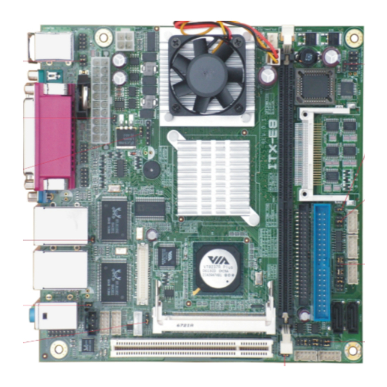
Jumper Locations on the ITX-E8 ITX-E8 User`s Manual... -
Page 20: Jp1: Lcd Panel Power Selection
Disable LAN 1 LAN 2 JP4, JP8: COM Power Selection JP4, JP8 can be used to select the COM supple power: +5V,Ring-IN or +12V. JP4: COM2 Pin9 power or Ring-IN JP8: COM1 pin9 power or Ring-IN +12V ITX-E8 User`s Manual... -
Page 21: Jp5: Cf Card Mode Selection
Setting Function Pin 1-2 Normal Operation Short/Closed (default) Pin 2-3 Clear CMOS Short/Closed Content JP7: COM6 Power Pin (Pin9) JP7 can be used to select the COM supple power: +5V or +12V. JP7: COM6 Pin9 power +12V ITX-E8 User`s Manual... -
Page 22: At_Mode: At Mode Selection
AT_MODE: AT Mode Selection AT Mode ATX Mode PWRMODE: AT Mode Selection AT Mode ATX Mode ITX-E8 User`s Manual... -
Page 23: Com2Mode1 & Com4Mode1: Rs232/Rs422/Rs485
The Protocols of COM2 and COM4 can be set up through jumpers. COM2MODE1: COM2 Protocols selection. COM4MODE1: COM4 Protocols selection. The pin-out for each mode is illustrated on next chapter. COM2MODE1 I/F TYPE COM4MODE1 RS-232 RS-422 RS-485 ITX-E8 User`s Manual... -
Page 24: Connectors On The Itx-E8
Connectors on the ITX-E8 The connectors on the ITX-E8 allow you to connect external devices such as keyboard, floppy disk drives, hard disk drives, printers and etc. The following table lists the connectors on ITX-E8 and their respective page number. -
Page 25: Connector Locations On The Itx-E8
Connector Locations on the ITX-E8 (1) (2) ITX-E8 User`s Manual... -
Page 26: Front Panel Connector
ATX Power ON/OFF Button This 2-pin connector acts as the “Power Supply On/Off Switch” on the ITX-E8 main board. When pressed, the switch will force the Main board to power on. When pressed again, it will force the main board to power off. -
Page 27: Backlight Connector
The reset switch allows the user to reset the system without turning the main power switch off and then on. Orientation is not required when making a connection to this header. RESET Signal Name Pin # SYS_RST Ground BACKLIGHT Connector Pin # Signal Name +12V Brightness ON/OFF ITX-E8 User`s Manual... -
Page 28: Irda Connector
DIO port supports 8 digital I/O bits. Each bit can be configured as Input or output individually. All bits are 5V tolerant. Signal Name Pin # Pin # Signal Name DIO_0 DIO_4 DIO_1 DIO_5 DIO_2 DIO_6 DIO_3 DIO_7 ITX-E8 User`s Manual... -
Page 29: Eide Connectors
Host data 15 Ground DRQ0 Ground Host IOW Ground Host IOR Ground IOCHRDY Host ALE DACK0 Ground IRQ14 No connect Address 1 P66DET Address 0 Address 2 Chip select 0 Chip select 1 Activity Ground No connect ITX-E8 User`s Manual... - Page 30 Host data 0 Host data 15 Ground DRQ1 Ground Host IOW Ground Host IOR Ground IOCHRDY Host ALE DACK1 Ground IRQ15 No connect Address 1 S66DET Address 0 Address 2 Chip select 0 Chip select 1 Activity Ground ITX-E8 User`s Manual...
-
Page 31: Com1 Serial Port
COM1 Serial Port COM1, a 9-pins D-Sub male connector, is the onboard COM1 serial port of the ITX-E8. The following table shows its pin assignments. Pin # RS232 Mode Signal Name DCD, Data carrier detect RXD, Receive data TXD, Transmit data... -
Page 32: Com3 Serial Port
COM3 Serial Port COM3, a 10-pins header connector, is the onboard COM3 serial port of the ITX-E8. The following table shows its pin assignments. Pin # RS232 Mode Signal Name DCD, Data carrier detect RXD, Receive data TXD, Transmit data... -
Page 33: Com5 Serial Port
COM5 Serial Port COM5, a 10-pins header connector, is the onboard COM5 serial port of the ITX-E8. The following table shows its pin assignments. Pin # RS232 Mode Signal Name DCD, Data carrier detect RXD, Receive data TXD, Transmit data... -
Page 34: Lpt Port
The LPT parallel port is a standard DSUB 25-pins Female connector. It can be configured as EPP or ECP or SPP mode. Signal Name Pin # Pin # Signal Name Strobe DATA0 DATA1 DATA2 DATA3 DATA4 DATA5 DATA6 DATA7 /ACK BUSY SLCT /AUTOFD /ERROR /INIT SELIN ITX-E8 User`s Manual... -
Page 35: Ps/2 Keyboard & Mouse Connector
Pin # Signal Name Keyboard/Mouse data Keyboard/Mouse clock VGA Connector The pin assignments of VGA CRT connector are as follows: Signal Name Pin # Pin # Signal Name Green Blue N.C. N.C. N.C. DDC_DATA HSYNC VSYNC DDC_CLK ITX-E8 User`s Manual... -
Page 36: Int_Vga Connector
Signal Name GREEN BLUE HSYNC DDC_DATA VSYNC DDC_CLK INT_KBMS Connector INT_KBMS is for internal input devices or MSR connection. The pin out is listed as below: Signal Name Pin # Pin # Signal Name KB-DATA MS-CLOCK KB-CLOCK MS-DATA ITX-E8 User`s Manual... -
Page 37: Atx-20P Power Connector
ATX-20P Power Connector The ATX-20P power connector supplies power to the whole Main board. Pin # Signal Name 3.3V 3.3V Power Good 5VSB(stand by +5V) +12V 3.3V -12V PS_ON(softOn/Off) ITX-E8 User`s Manual... -
Page 38: Atx_12V Power Connector
This is a 3-pins header for the CPU fan. Pin # Signal Name 3 2 1 Ground +12V SPEED System Fan Power Connector This is a 3-pins header for the System fan. Pin # Signal Name 3 2 1 Ground +12V SPEED ITX-E8 User`s Manual... -
Page 39: Sata1, Sata2 Connectors
Pin # Signal Name SATARX+ SATARX- SATATX- SATATX+ USB12, USB34 Connectors The following table shows the pin outs of the USB12 USB34 connectors. Signal Name Pin # Pin # Signal Name N.C. USB- USB+ USB+ USB- N.C. ITX-E8 User`s Manual... -
Page 40: Lanrj45+Usbx2 Connectors
LAN- RJ45 Connectors This connector is for the 10/100/1000Mbps Ethernet capability. The figure below shows the pin out assignments of this connector and its corresponding input jack. Pin # Signal Name MDI0+ MDI0- MDI1+ MDI1- MDI2+ MDI2- MDI3+ MDI3- ITX-E8 User`s Manual... -
Page 41: Lan Rj45 Leds
100 Mbps 10 Mbps AUDIO Connector After install onboard audio driver, you may connect speaker to Lin Out jack, microphone to MIC In jack. Audio sources devices like CD-ROM, walkman and etc can be connected to Lin-In jack. ITX-E8 User`s Manual... -
Page 42: Int_Audio Connector
LINEOUT-L LINEOUT-R MIC1-IN MIC2-IN CENTER OUT LFE OUT SURR OUTL SURR OUTR CD_IN Connector CD_IN connector is designed for wire the CD_ROM audio signals to the on-board Audio CODEC. Pin # Signal Name CD_Left CD_AGND CD_AGND CD_Right ITX-E8 User`s Manual... -
Page 43: Lvds Lcd Connector
+12V LCDVDD 5V/3.3V LCDVDD 5V/3.3V BRIGHTNES BCKLITE_ON LVDS_GND LVDS_GND CHA_TX0+ CHB_TX0+ CHA_TX0- CHB_TX0- LVDS_GND LVDS_GND CHA_TX1+ CHB_TX1+ CHA_TX1- CHB_TX1- LVDS_GND LVDS_GND CHA_TX2+ CHB_TX2+ CHA_TX2- CHB_TX2- LVDS_GND LVDS_GND CHA_TXC+ CHB_TXC+ CHA_TXC- CHB_TXC- LVDS_GND LVDS_GND CHA_TX3+ CHB_TX3+ CHA_TX3- CHB_TX3- ITX-E8 User`s Manual... -
Page 44: Chapter 3 Bios Setup
Chapter 3 BIOS Setup This chapter describes the different settings available in the Award BIOS that comes with the ITX-E8 CPU card. The topics covered in this chapter are as follows: BIOS Introduction ........... 37 Main Menu ............... 40 Standard CMOS Setup..........42 Advanced BIOS Features ........ -
Page 45: Bios Introduction
RAM so that it retains the Setup information when the power is turned off. The AwardBIOS™ installed in ITX-E8 is a custom version of an industry standard BIOS. This means that it supports VIA C7/EDEN in a standard IBM-AT compatible input/output system. -
Page 46: Using Setup
Use the left and right arrow keys to choose the menu you want to be in. To display a sub menu Use the arrow keys to move the cursor to the sub menu you want. Then press <Enter>. A “ ” pointer marks all sub menus. ITX-E8 User`s Manual... -
Page 47: Getting Help
To this end, we strongly recommend that you avoid making any changes to the chipset defaults. These defaults have been carefully chosen by both Award and ITX-E8 manufacturer to provide the absolute maximum performance and reliability. Even a seemingly small change to the chipset setup has the potential for causing you to use the override. -
Page 48: Main Menu
Setup Items The main menu includes the following main setup categories. Standard CMOS Features Use this menu for basic system configuration. Advanced BIOS Features Use this menu to set the Advanced Features available on your system. ITX-E8 User`s Manual... -
Page 49: Advanced Chipset Features
Supervisor / User Password Use this menu to set User and Supervisor Passwords. Save & Exit Setup Save CMOS value changes to CMOS and exit setup. Exit Without Save Abandon CMOS value changes exit setup. ITX-E8 User`s Manual... -
Page 50: Standard Cmos Setup
Drive A [None] Drive B [None] Video [EGA/VGA] Halt On [No Errors] Base Memory 640K Extended Memory 194560K Total Memory 195584K ↑↓→←: Move Enter: Select +/-/PU/PD: Value F10:Save ESC: Exit F1:General Help F5:Previous Values F6:Fail-safe Defaults F7:Optimized Defaults ITX-E8 User`s Manual... - Page 51 All, but Disk/Key Base Memory Displays the amount of conventional memory detected during boot up Extended Memory Displays the amount of extended memory detected during boot up Total Memory Displays the total memory available in the system ITX-E8 User`s Manual...
-
Page 52: Channel 0 Hdds / Channel
↑↓→←: Move Enter: Select +/-/PU/PD:Value F10:Save ESC:Exit F1:General Help F5:Previous Values F6:Fail-safe Defaults F7:Optimized Defaults Use the legend keys to navigate through this menu and exit to the main menu. Use the Table listed below to configure the hard disk. ITX-E8 User`s Manual... - Page 53 Min = 0 **** Warning: Setting a value of Max = 65535 65535 means no hard disk Landing zone Min = 0 **** Max = 65535 Sector Min = 0 Number of sectors per track Max = 255 ITX-E8 User`s Manual...
-
Page 54: Drive A / Drive B
The system boot will not be halted for a disk error; it will stop for all other errors. All, But Disk/Key The system boot will not be halted for a key- board or disk error; it will stop for all others. ITX-E8 User`s Manual... -
Page 55: Advanced Bios Features
MPS Version Control For OS [1.4] OS Select For DRAM > 64MB [Non-OS2] Video BIOS Shadow [Enabled] Small Logo(EPA) Show [Disabled] ↑↓→←: Move Enter: Select +/-/PU/PD: Value F10:Save ESC: Exit F1:General Help F5:Previous Values F6:Fail-safe Defaults F7:Optimized Defaults ITX-E8 User`s Manual... -
Page 56: Cpu Feature
Vcore to designated voltage. In the mean time, the core frequency speed will also slow down to (FSB MHz X Bus Ratio) MHz. The choice: Thermal Monitor 1, Thermal Monitor 2. TM2 Bus Ratio The choice: 15X. TM2 Bus VID The choice: 1.004V. ITX-E8 User`s Manual... -
Page 57: Hard Disk Boot Priority
No warning message will appear when anything attempts to access the boot sector or hard disk partition table. CPU L1 & L2 Cache These two categories speed up memory access. However, it depends on CPU/chipset design. Enabled Enable cache Disabled Disable cache ITX-E8 User`s Manual... -
Page 58: Cpu L2 Cache Ecc Checking
The choice: 6, 8, 10, 12, 15, 20, 24, 30. Typematic Delay (Msec) Sets the delay time after the key is held down before it begins to repeat the keystroke. The choice: 250, 500, 750, 1000. ITX-E8 User`s Manual... -
Page 59: Security Option
Select OS2 only if you are running OS/2 operating system with greater than 64MB of RAM on the system. The choice: Non-OS2, OS2. Video BIOS Shadow Enabled copies Video BIOS to shadow RAM Improves performance. The choice: Enabled, Disabled. Small Logo(EPA) Show The choice: Enabled, Disabled. ITX-E8 User`s Manual... -
Page 60: Advanced Chipset Features
Such a scenario might well occur if your system had mixed speed DRAM chips installed so that greater delays may be required to preserve the integrity of the data held in the slower memory chips. ITX-E8 User`s Manual... -
Page 61: Dram Clock/Drive Control
Current DRAM Frequency The choice: 200MHz. DRAM Clock The choice: By SPD, 100MHz, 133MHz, 166MHz, 200MHz. DRAM Timing The choice: Manual, Auto By SPD. SDRAM CAS Latency [DDR/DDR The choice: 2.5/ 4. Bank Interleave The choice: Disabled. ITX-E8 User`s Manual... -
Page 62: Precharge To Active(Trp)
Item Help VGA Share Memory Size [64M] Direct Frame Buffer [Enabled] Menu Level Select Display Device [CRT+LCD] Panel Type [02] ↑↓→←: Move Enter: Select +/-/PU/PD: Value F10:Save ESC: Exit F1:General Help F5:Previous Values F6:Fail-safe Defaults F7:Optimized Defaults ITX-E8 User`s Manual... -
Page 63: Agp Aperture Size
Phoenix – AwardBIOS CMOS Setup Utility CPU & PCI Bus Control PCI Master 0 WS Write [Enabled] Item Help PCI Delay Transaction [Enabled] Menu Level ↑↓→←: Move Enter: Select +/-/PU/PD: Value F10:Save ESC: Exit F1:General Help F5:Previous Values F6:Fail-safe Defaults F7:Optimized Defaults ITX-E8 User`s Manual... -
Page 64: Pci Master 0 Ws Write
F0000h-FFFFFh, resulting in better system performance. However, if any program writes to this memory area, a system error may result. The choice: Enabled, Disabled. Video RAM Cacheable The choice: Enabled, Disabled. Init Display First The choice: PCI Slot, AGP. ITX-E8 User`s Manual... -
Page 65: Integrated Peripherals
Primary Master UDMA [Auto] Primary Slave UDMA [Auto] Secondary Master UDMA [Auto] Secondary Slave UDMA [Auto] IDE HDD Block Mode [Enabled] ↑↓→←: Move Enter: Select +/-/PU/PD: Value F10:Save ESC: Exit F1:General Help F5:Previous Values F6:Fail-safe Defaults F7:Optimized Defaults ITX-E8 User`s Manual... -
Page 66: Onchip Sata
The choice: Auto, Disabled. IDE HDD Block Mode If your IDE hard drive supports block mode select Enabled for automatic detection of the optimal number of block read/writes per sector the drive can support. The choice: Enabled, Disabled. ITX-E8 User`s Manual... -
Page 67: Via Onchip Pci Device
OnChip EHCI Controller The choice: Enabled, Disabled. USB Emulation Don’t support any USB device on DOS. KB/MS Support USB legacy Keyboard and Mouse, No Support USB Storage. Support USB legacy Keyboard, Mouse and Storage. The choice: OFF, KB/MS, ON. ITX-E8 User`s Manual... -
Page 68: Usb Keyboard Support
Onboard Serial Port 1/Port 2 Select an address and corresponding interrupt for the first and second serial ports. The choice: 3F8/IRQ4, 2F8/IRQ3, 3E8/IRQ4, 2E8/IRQ3, Disabled, Auto. UART Mode Select The choice: IrDA, ASKIR, Normal. RxD, TxD Active The choice: Hi, Lo. ITX-E8 User`s Manual... -
Page 69: Ir Transmission Delay
Onboard Serial Port 3/Port 4/Port 5/Port 6 The choice: 4F8, 3F8, 2F8, 4E8, 3E8, 2E8, Disabled. Serial Port 3/Port 4/Port 5/Port 6 Use IRQ The choice: IRQ3, IRQ4, IRQ5, IRQ7, IRQ10, IRQ11. Watch Dog Timer Select The choice: Enable, Disabled. ITX-E8 User`s Manual... -
Page 70: Power Management Setup
[Press Enter] ↑↓→←: Move Enter: Select +/-/PU/PD: Value F10:Save ESC: Exit F1:General Help F5:Previous Values F6:Fail-safe Defaults F7:Optimized Defaults ACPI Function This item allows you to enable/disable the Advanced Configuration and Power Management (ACPI). The choice: Enabled, Disabled. ITX-E8 User`s Manual... -
Page 71: Power Management Option
8 Min, 9 Min, 10 Min, 11 Min, 12 Min, 13 Min, 14 Min, 15 Min. Suspend Mode The choice: 1Min, 2Min, 4Min, 6 Min, 8Min, 10Min, 20Min, 30Min, 40Min, 1Hour, Disable. Video Off Option The choice: Always On, Suspend -> Off. ITX-E8 User`s Manual... -
Page 72: Video Off Method
RTC Alarm Resume [Disabled] X Date (of Month) X Resume Time 0 : 0 : 0 IRQs Activity Monitoring [Press Enter] ↑↓→←: Move Enter: Select +/-/PU/PD: Value F10:Save ESC: Exit F1:General Help F5:Previous Values F6:Fail-safe Defaults F7:Optimized Defaults ITX-E8 User`s Manual... -
Page 73: Ps2Kb Wakeup Select
The choice: NONE, LPT, COM, LPT/COM. HDD & FDD The choice: OFF, ON. PCI Master The choice: OFF, ON. PowerOn by PCI Card The choice: Enabled, Disabled. Modem Ring Resume The choice: Enabled, Disabled. RTC Alarm Resume The choice: Enabled, Disabled. ITX-E8 User`s Manual... -
Page 74: Date (Of Month)
↑↓→←: Move Enter: Select +/-/PU/PD: Value F10:Save ESC: Exit F1:General Help F5:Previous Values F6:Fail-safe Defaults F7:Optimized Defaults Primary INTR The choice: OFF, ON. IRQ3 (COM 2) The choice: Enabled, Disabled. IRQ4 (COM 1) The choice: Enabled, Disabled. ITX-E8 User`s Manual... -
Page 75: Irq5 (Lpt 2)
IRQ10 (Reserved) The choice: Enabled, Disabled. IRQ11 (Reserved) The choice: Enabled, Disabled. IRQ12 (PS/2 Mouse) The choice: Enabled, Disabled. IRQ13 (Coprocessor) The choice: Enabled, Disabled. IRQ14 (Hard Disk) The choice: Enabled, Disabled. IRQ15 (Reserved) The choice: Enabled, Disabled. ITX-E8 User`s Manual... -
Page 76: Pnp/Pci Configuration Setup
Default is Disabled. Select Enabled to reset Extended System Configuration Data (ESCD) when you exit Setup if you have installed a new add-on and the system reconfiguration has caused such a serious conflict that the OS cannot boot. The choice: Enabled, Disabled. ITX-E8 User`s Manual... -
Page 77: Resources Controlled By
Plug and Play standard whether designed for PCI or ISA bus architecture. The Choice: Legacy ISA and PCI/ISA PnP. PCI/VGA Palette Snoop Leave this field at Disabled. The choice: Enabled, Disabled. Assign IRQ For VGA The choice: Enabled, Disabled. Assign IRQ For USB The choice: Enabled, Disabled. ITX-E8 User`s Manual... -
Page 78: Pc Health Status
CPU Warning Temperature Select the CPU over-heated warning temperature. °C/122°F, 53°C/127°F, 56°C/133°F, 60°C/140°F, The choice: Disabled, 50 63°C/145°F, 66°C/151°F, 70°C/158°F. Current System Temp Show System Temperature. Current CPUDEI Temp Shows CPUDEI Temp. Current CPU Temperature Shows Board Temperature. ITX-E8 User`s Manual... -
Page 79: Current Cpufan Speed
Shows CPUFAN speed. Current SYSFAN Speed Shows SYSFAN speed. Vcore/1.5V/3.3V/5V/12V/-12V/VBAT/5VSB Voltages Shows Power rails voltage. Shutdown Temperature °C/140°F, 65°C/149°F, 70°C/158°F, 75°C/167°F. The choice: Disabled, 60 CPU FAN Control The choice: Enabled, Disabled SYSTEM FAN Control The choice: Enabled, Disabled ITX-E8 User`s Manual... -
Page 80: Frequency/Voltage Control
Menu Level ↑↓→←: Move Enter: Select +/-/PU/PD: Value F10:Save ESC: Exit F1:General Help F5:Previous Values F6:Fail-safe Defaults F7:Optimized Defaults CPU Clock Ratio The choice: Min= Max= Key in DEC number: Spread Spectrum The choice: Disabled, 0.20%, 0.25%, 0.35%. ITX-E8 User`s Manual... -
Page 81: Load Fail-Safe Defaults
When you press <Enter> on this item you get a confirmation dialog box with a message similar to: Load Optimized Defaults (Y/N) ? N Pressing ‘Y’ loads the default values that are factory settings for optimal performance system operations. ITX-E8 User`s Manual... -
Page 82: Supervisor/User Password Setting
Features Setup Menu and its Security option. If the Security option is set to “System”, the password will be required both at boot and at entry to Setup. If set to “Setup”, prompting only occurs when trying to enter Setup. ITX-E8 User`s Manual... -
Page 83: Exit Selecting
Pressing <Enter> on this item asks for confirmation: Quit without saving (Y/N)? N This allows you to exit Setup without storing in CMOS any change. The previous selections remain in effect. This exits the Setup utility and restarts your computer. ITX-E8 User`s Manual... -
Page 84: Chapter 4 Appendix
CHAPTER 4 Appendix I/O Port Address Map ..........77 Interrupt Request Lines(IRQ)......... 78 POST Beep .............. 79 ITX-E8 User`s Manual... -
Page 85: I/O Port Address Map
Parallel Port #1(LPT1) 360 - 36F Network Ports 3B0 - 3BF Monochrome & Printer adapter 3C0 - 3CF EGA adapter 3D0 - 3DF CGA adapter 3F0h - 3F7h Floppy Disk Controller 3F8h - 3FFh Serial Port #1(COM1) ITX-E8 User`s Manual... -
Page 86: Interrupt Request Lines (Irq)
Serial Port #1 IRQ5 Reserved IRQ6 Floppy Disk Controller IRQ7 Parallel Port #1 IRQ8 Real Time Clock IRQ9 Software Redirected to Int 0Ah IRQ10 Reserved IRQ11 Reserved IRQ12 PS/2 Mouse IRQ13 80287 IRQ14 Primary IDE IRQ15 Secondary IDE ITX-E8 User`s Manual... -
Page 87: Post Beep
This beep code consists of a single long beep followed by two short beeps. The other code indicates that your DRAM error has occurred. This beep code consists of a single long beep repeatedly. ITX-E8 User`s Manual...
Need help?
Do you have a question about the ITX-E8 and is the answer not in the manual?
Questions and answers