Table of Contents
Advertisement
Quick Links
Advertisement
Table of Contents

Related Manuals for ETOP ATX-E15


Summary of Contents for ETOP ATX-E15
- Page 1 ATX-E15 Intel® Core™2 Quad Q35 EATX Main-Board User’s Manual Version 1.0...
- Page 2 IBM, PS/2 are trademarks of International Business Machines Corporation. Intel Pentium4 are registered trademarks of Intel Corporation. Microsoft Windows is a registered trademark of Microsoft Corporation. All other product names or trademarks are properties of their respective owners. ATX-E15 User`s Manual...
-
Page 3: Table Of Contents
JUMPER SETTING & CONNECTORS ............. 9 2.1 J ATX-E15 .............. 10 UMPERS ON THE Jumper Locations on the ATX-E15 ..........11 JP1: Clear CMOS RAM Data ............12 JP2, JP3, JP4: Front Side Bus Selection .......... 13 JP5: CF Card Mode Selection ............13 JP6: COM1 Power Selection ............ - Page 4 PPM Mode ................... 44 Limit CPUID Max Val ................44 C1E Function ..................44 Execute Disabled Bit ................44 Virtualization Technology ..............44 Core Multi-Processing ................. 44 Hard Disk Boot Priority ..............45 Bootable Add-in Cards ................. 45 ATX-E15 User`s Manual...
- Page 5 On Chip IDE Device ............... 54 IDE HDD Block Mode ................55 IDE DMA transfer access ..............55 IDE Primary/Secondary, Master/Slave PIO ........55 IDE Primary/Secondary, Master/ Slave UDMA ........55 On-Chip Secondary PCI IDE ..............56 SATA Mode ..................56 ATX-E15 User`s Manual...
- Page 6 Soft-Off by PWR-BTTN ..............65 CPU THRM-Throttling ..............65 Wake-Up by PCI card ..............65 Power On by Ring ................. 65 Resume by Alarm ..............66 Date (of Month) Alarm ..............66 Time (hh: mm: ss) Alarm .............. 66 ATX-E15 User`s Manual...
- Page 7 3.12 S & E ............... 77 ETUP 3.13 E ..............77 ITHOUT AVING CHAPTER 4 APPENDIX ..............79 A. I/O P ..............80 DDRESS B. I (IRQ) ............81 NTERRUPT EQUEST INES C. POST B ..................82 ATX-E15 User`s Manual...
- Page 8 Contents This page is intentionally left blank viii ATX-E15 User`s Manual...
-
Page 9: Introduction
Introduction This manual is designed to give you information on the ATX-E15 Single Board Computer card. The topics covered in this manual are as follows: Features Specification Jumper setting and Connectors BIOS Setup Appendix ATX-E15 User`s Manual... -
Page 10: Chapter 1
Chapter 1 Features & Specifications ....................3 EATURES ..................4 PECIFICATIONS ATX-E15 User`s Manual... -
Page 11: Features
Microphone, CD-IN, SPDIF and surrounding sounds. Five standard 32-bits 5V PCI slots for PCI add-on cards. One PCI-Express x16 slot for high-end graphics add-on card. One PCI-Express x4 slot for high-end Storage RAID Cards or Multiple-ports LAN Cards. ATX-E15 User`s Manual... -
Page 12: Specifications
Six USB2.0 ports for internal or front panel connection. ( 2x5 pin-header/ 2.54mm pitch). Four USB2.0 ports integrated with RJ45 connector on rear panel. One PS2 Keyboard and one PS2 mouse connector on rear panel. ATX-E15 User`s Manual... - Page 13 Five 5V 32-bits PCI slots for PCI 32-bits 5V/3V Add-on Cards. One PCI-Express x16 slot for high-end graphics add-on card. One PCI-Express x4 slot for high-end Storage RAID Cards or Multiple-ports LAN Cards. Hardware Monitor: 83627HF integrated hardware monitor chip to monitor ATX-E15 User`s Manual...
- Page 14 Software programmable to configure as 4-IN/4-OUT or 8-IN or 8-OUT. Others: One Buzzer (9mm) on-board for beep message. Operating Temperature: 0~60°C Operation Range. -40C to 70C storage. Relative Humility: 5~95%, non-condensing. ATX-E15 User`s Manual...
- Page 15 Dimensions: 9.6”(L) x 12” (W); or 244mm (L) x 305mm (W). Standard Full-Size ATX form factor. ATX-E15 User`s Manual...
- Page 16 This page is intentionally left blank ATX-E15 User`s Manual...
-
Page 17: Chapter 2
Chapter 2 Jumper setting & Connectors 2.1 J ATX-E15 ............... 10 UMPERS ON THE 2.2 C ATX-E15 ............15 ONNECTORS ON THE ATX-E15 User`s Manual... -
Page 18: Umpers On The Atx-E15
2.1 Jumpers on the ATX-E15 The jumpers on the ATX-E15 allow you to configure your Single Board Computer card according to the needs of your applications. If you have doubts about the best jumper configuration for your needs, contact your dealer or sales representative. -
Page 19: Jumper Locations On The Atx-E15
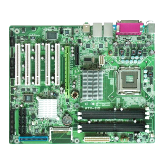
Jumper Locations on the ATX-E15 ATX-E15 User`s Manual... -
Page 20: Jp1: Clear Cmos Ram Data
(3) Short the pin2 and pin3 for three seconds. (4) Put Jumper cap back to pin1 & 2. (5) Turn on your computer. (6) Hold Down <Delete> during boot up and enter BIOS setup to enter your preferences. Clear CMOS Normal Operation Content (default) ATX-E15 User`s Manual... -
Page 21: Jp2, Jp3, Jp4: Front Side Bus Selection
This Jumper is to select the CF works as Secondary Channel Master device or Slave device. Master Slave JP6: COM1 Power Selection JP6 can be used to select the COM1 supply power: +5V, Ring-IN or +12V. +12V ATX-E15 User`s Manual... -
Page 22: Jp7: Com4 Power Selection
JP7: COM4 Power Selection JP7 can be used to select the COM4 supply power: +5V or +12V. +12V AT_MODE: Power Supply Mode Selection AT mode ATX mode AT_MODE AT_MODE ATX-E15 User`s Manual... -
Page 23: Connectors On The Atx-E15
The connectors on the ATX-E15 allow you to connect external devices such as keyboard, floppy disk drives, hard disk drives, printers and etc. The following table lists the connectors on ATX-E15 Connector Locations on the ATX-E15..........16 DIO Connector ................17 USB12, USB34, USB56 Connectors .......... -
Page 24: Connector Locations On The Atx-E15
Connector Locations on the ATX-E15 ATX-E15 User`s Manual... -
Page 25: Dio Connector
DIO_6 DIO_2 DIO_5 DIO_1 DIO_4 DIO_0 USB12, USB34, USB56 Connectors The following table shows the pin outs of the USB12, USB34, USB56 connectors. Signal Name Pin # Pin # Signal Name N.C. USB- USB+ USB+ USB- N.C. ATX-E15 User`s Manual... -
Page 26: Sata1~6 Connectors
Pin # Signal Name SATARX+ SATARX- SATATX- SATATX+ VGA Connector The pin assignments of VGA CRT connector are as follows: Signal Name Pin # Pin # Signal Name Green Blue N.C. N.C. N.C. DDC_DATA HSYNC VSYNC DDC_CLK ATX-E15 User`s Manual... -
Page 27: Lanrj45+Usbx2 Connectors
LAN- RJ45 Connectors This connector is for the 10/100/1000Mbps Ethernet capability. The figure below shows the pin out assignments of this connector and its corresponding input jack. Pin # Signal Name MDI0+ MDI0- MDI1+ MDI1- MDI2+ MDI2- MDI3+ MDI3- ATX-E15 User`s Manual... -
Page 28: Lan Rj45 Leds
100 Mbps 10 Mbps AUDIO Connector After install onboard audio driver, you may connect speaker to Lin Out jack, microphone to MIC In jack. Audio sources devices like CD-ROM, walkman and etc can be connected to Lin-In jack. ATX-E15 User`s Manual... -
Page 29: Int_Audio Connector
Pin # Signal Name SURR-OUT_R SURR-OUT_L CENTER-OUT LFE-OUT MICI-IN_R MICI-IN_L LINE-OUT_R LINE-OUT_L LINE-IN_R LINE-IN_L CD_IN Connector CD_IN connector is designed for wire the CD_ROM audio signals to the on-board Audio CODEC. Pin # Signal Name CD_Left CD_Right ATX-E15 User`s Manual... -
Page 30: Atx-24P Connector
Signal Name 3.3V 3.3V 3.3V -12V PS_ON- PWROK 5VSB +12V +12V 3.3V PS/2 Keyboard & Mouse Connector The following table describes the pin assignment of PS/2 Keyboard and Mouse connector. Pin # Signal Name Keyboard/Mouse data Keyboard/Mouse clock ATX-E15 User`s Manual... -
Page 31: Front_Panel Connector
PWRBTN1 (ATX Power ON/OFF Button) This 2-pin connector acts as the “Power Supply On/Off Switch” on the ATX-E15 main board. When pressed, the switch will force the Main board to power on. When pressed again, it will force the main board to power off. -
Page 32: System Fan Connector
CPU FAN Connector This is a 3-pin header for the CPU fan. Pin # Signal Name Ground +12V CPUPWM PWR FAN Connector This is a 3-pin header for the PWR fan. Pin # Signal Name Ground +12V PWRPWM ATX-E15 User`s Manual... -
Page 33: Lpt Port
Signal Name Strobe AUTOFD DATA0 ERROR DATA1 INIT SLIN DATA2 DATA3 DATA4 DATA5 DATA6 DATA7 BUSY SLCT IRDA Connector This connector is used for an IRDA connector for wireless communication. IrDA Pin # Signal Name IR-RX Ground IR-TX ATX-E15 User`s Manual... -
Page 34: Cf-Ii Connector
Name PDD3 PDD4 PDD5 PDD6 PDD7 PCS1- PDA2 PDA1 PDA0 PDD0 PDD1 PDD2 N.C. N.C. N.C. PDD11 PDD12 PDD13 PDD14 PDD15 PCS3- N.C. PDIOR- PDIOW- IRQ14 MST#_SLV N.C. PST1- PIORDY PDDREQ PDDACK- CF_LED- N.C. PDD8 PDD9 PDD10 ATX-E15 User`s Manual... -
Page 35: Com1 Serial Port
RXD, Receive data RX+ (422) TXD, Transmit data RX- (422) DTR, Data terminal ready GND, ground N.C. DSR, Data set ready N.C. RTS, Request to send N.C. CTS, Clear to send N.C. +5V,Ring-IN or +12V N.C. N.C. ATX-E15 User`s Manual... -
Page 36: Com3 Serial Port
Pin # RS232 Mode Signal Name DCD, Data carrier detect RXD, Receive data TXD, Transmit data DTR, Data terminal ready GND, ground DSR, Data set ready RTS, Request to send CTS, Clear to send +5V,Ring-IN or +12V N.C. ATX-E15 User`s Manual... -
Page 37: Pide Connector
LAN_LED1 Connector The 4-pins LAN_LED1 connector designed for LAN1 port is for applications need to display LAN1 port status on front panel or the places administrators are easy to access. Pin # Signal Name 1_ACTLED 1_PULUP 1_LINK1000 1_LINK100 ATX-E15 User`s Manual... -
Page 38: Lan_Led2 Connector
SPDIFI ATX_12V Power Connector The ATX_12V power connector mainly supplies power to the CPU. Caution! If the ATX_12V power connector is not connected, the system will not start. Pin # Signal Name ATX_12V +12V +12V +12V +12V ATX-E15 User`s Manual... -
Page 39: Floppy Drive Connector
Drive select 1 Ground Drive select 0 Ground Motor enable 1 Ground Direction Ground Step Ground Write data Ground Write gate Ground Track 00 Ground Write protect Ground Read data Ground Side 1 select Ground Diskette change ATX-E15 User`s Manual... - Page 40 This page is intentionally left blank ATX-E15 User`s Manual...
-
Page 41: Chapter 3 Bios Setup
Chapter 3 BIOS Setup This chapter describes the different settings available in the Award BIOS that comes with the ATX-E15 CPU card. The topics covered in this chapter are as follows: 3.1 M .................. 35 3.2 S CMOS F ............37... -
Page 42: Bios Introduction
And the firmware chip will store the setup utility on the board. However, if you want to enter the setup after the POST, you can press Ctrl + Alt + Del simultaneously or turn off the power then back on. ATX-E15 User`s Manual... -
Page 43: Main Menu
Use this menu for basic system configuration. Advanced BIOS Features Use this menu to set the Advanced Features available on your system. Advance Chipset Features Use this menu to change the values in the chipset registers and optimize your system's performance. ATX-E15 User`s Manual... -
Page 44: Integrated Peripherals
Set Supervisor/ User Password Use this menu to set User and Supervisor Passwords. Save & Exit Setup Save CMOS value changes to CMOS and exit setup. Exit Without Saving Abandon all CMOS value changes and exit setup. ATX-E15 User`s Manual... -
Page 45: Standard Cmos Features
Video [EGA/VGA] Halt On [All , But Disk/Key] Base Memory 639K Extend Memory 1037312K Total Memory 1038336K ↑↓← → :Move Enter: Select +/-/PU/PD: Value F10:Save Esc: Exit F1:General Help F5:Previous Value F6:Fail-Safe Defaults F7:Optimized Default (Figure 2) ATX-E15 User`s Manual... - Page 46 All, but Disk/Key Base Memory Displays the amount of conventional memory detected during boot up Extended Memory Displays the amount of extended memory detected during boot up Total Memory Displays the total memory available in the system ATX-E15 User`s Manual...
-
Page 47: Ide Channel 0, 1 Master/ Slave
To auto-detect the HDD’s Capacity 0 MB size, head…on this channel Cylinder Head Precomp Landing Zone Sector ↑↓← → :Move Enter: Select +/-/PU/PD: Value F10:Save Esc: Exit F1:General Help F5:Previous Value F6:Fail-Safe Defaults F7:Optimized Default (Figure 3) ATX-E15 User`s Manual... -
Page 48: Ide Channel 2, 3 Master
↑↓← → :Move Enter: Accept Esc: Abort Precomp Landing Zone Sector ↑↓← → :Move Enter: Select +/-/PU/PD: Value F10:Save Esc: Exit F1:General Help F5:Previous Value F6:Fail-Safe Defaults F7:Optimized Default (Figure 4) Extended IDE Drive The choice: None, Auto (default) ATX-E15 User`s Manual... - Page 49 Min = 0 **** Warning: Setting a value Max = 65535 of 65535 means no hard disk Landing zone Min = 0 **** Max = 65535 Sector Min = 0 Number of sectors per track Max = 255 ATX-E15 User`s Manual...
-
Page 50: Drive A/B
The system boot will not be halted for a disk error; it will stop for all other errors. All, But Disk/Key The system boot will not be halted for a key- board or disk error; it will stop for all others. (default) ATX-E15 User`s Manual... -
Page 51: Advanced Bios Features
MPS Version Control For OS [1.4] OS Select For DRAM > 64MB [Non-OS2] Report No FDD For WIN 95 [No] ↑↓← → :Move Enter: Select +/-/PU/PD: Value F10:Save Esc: Exit F1:General Help F5:Previous Value F6:Fail-Safe Defaults F7:Optimized Default (Figure 5) ATX-E15 User`s Manual... -
Page 52: Cpu Feature
Limit CPUID Max Val The choice: Enabled, Disabled (default). C1E Function The choice: Auto (default), Disabled. Execute Disabled Bit The choice: Enabled, Disabled (default). Virtualization Technology The choice: Enabled (default), Disabled. Core Multi-Processing The choice: Enabled (default), Disabled. ATX-E15 User`s Manual... -
Page 53: Hard Disk Boot Priority
F1:General Help F5:Previous Value F6:Fail-Safe Defaults F7:Optimized Default (Figure 7) Bootable Add-in Cards This is for setting the priority of the hard disk boot order when the “Hard Disk” option is selected in the “*First/Second/Third+ Boot Device “menu item. ATX-E15 User`s Manual... - Page 54 The BIOS attempts to load the operating system from the devices in the sequence selected in these items. The Choice: Floppy, LS120, Hard-Disk, ZIP100, CDROM, Disabled, USB-FDD, USB-ZIP, USB-CDROM, Legacy LAN. Item Default First Boot Device Hard-Disk Second Boot Device CDROM Third Boot Device LS120 ATX-E15 User`s Manual...
- Page 55 Keystrokes repeat at a rate determined by the keyboard controller. When enabled, the typematic rate and typematic delay can be selected. The choice: Enabled, Disabled (default). If Typematic Rate Setting is [Enabled], can choice Rate and Delay: ATX-E15 User`s Manual...
- Page 56 Sets the delay time after the key is held down before it begins to repeat the keystroke. The choice: 250 (default), 500, 750, and 1000. Typematic Delay (Msec) ….. [ ….. [ ] ….. [ ] 1000 ….. [ ] : Move Enter: Accept ESC:Abort ATX-E15 User`s Manual...
- Page 57 OS Select For DRAM > 64MB Select OS2 only if you are running OS/2 operating system with greater than 64MB of RAM on the system. The choice: Non-OS2 (default), OS2. Report No FDD For WIN 95 The choice: No (default), Yes. ATX-E15 User`s Manual...
- Page 58 DVMT Mode [DVMT] DVMT / FIXED Memory Size [128MB] LAN1 Chip Control [Enabled] LAN2 Chip Control [Enabled] ↑↓← → :Move Enter: Select +/-/PU/PD: Value F10:Save Esc: Exit F1:General Help F5:Previous Value F6:Fail-Safe Defaults F7:Optimized Default (Figure 8) ATX-E15 User`s Manual...
- Page 59 Leave this on the default setting. The choice: Auto (default), 2, 3,4,5,6. Precharge dealy (tRAS) The choice: Auto (default), 4,5,6,7,8,9,10,11,12,13,14,15. System Memory Frequency The choice: Auto (default), 533MHz, 667MHz. System BIOS Cacheable The choice: Enabled (default), Disabled. ATX-E15 User`s Manual...
- Page 60 The choice: Onchip VGA, PEG Port, Auto (default). On-Chip Frame Buffer Size User can select frame buffer size. The choice: 1MB, 8MB (default). DVMT Mode This field shows the current DVMT mode. The choice: FIXED, DVMT (default), BOTH. ATX-E15 User`s Manual...
- Page 61 This field is used to select the graphics memory size used by DVMT/ Fixed mode. The choice: 64MB, 128MB (default), 224MB. LAN1 Chip Control The choice: Enabled (default), Disabled. LAN2 Chip Control The choice: Enabled (default), Disabled. ATX-E15 User`s Manual...
- Page 62 IDE Secondary Slave UDMA [Auto] of lock SATA Mode [IDE] read/writes per LEGACY Mode Support [Disabled] sector the drive can support ↑↓← → :Move Enter: Select +/-/PU/PD: Value F10:Save Esc: Exit F1:General Help F5:Previous Value F6:Fail-Safe Defaults F7:Optimized Default ATX-E15 User`s Manual...
- Page 63 The BIOS will automatically set the system according to your hard disk drive’s timing (default). Mode 0-4 You can select a mode that matches your hard disk drive’s timing. IDE Primary/Secondary, Master/ Slave UDMA The choice: Disabled, Auto (default). ATX-E15 User`s Manual...
- Page 64 F1:General Help F5:Previous Value F6:Fail-Safe Defaults F7:Optimized Default Onboard FDC Controller The choice: Enabled (default), Disabled. Onboard Serial Port 1 Select an address and corresponding interrupt for the first serial ports. The choice: Disable, 3F8/IRQ4 (default), 2F8/IRQ3, 3E8/IRQ4, 2E8/IRQ3, Auto. ATX-E15 User`s Manual...
- Page 65 F1:General Help F5:Previous Value F6:Fail-Safe Defaults F7:Optimized Default RxD, TxD Active The choice: UART Mode Select Hi, Hi ……[ ] Hi, Lo ……[ ] Lo, Hi …..[ ] Lo, Lo …..[ ] : Move Enter: Accept ESC: Abort ATX-E15 User`s Manual...
- Page 66 [378/IRQ7] Parallel Port Mode [SPP] x EPP Mode Select EPP1.7 x ECP Mode Use DMA PWRON After PWR-Fail [Off] ↑↓← → :Move Enter: Select +/-/PU/PD: Value F10:Save Esc: Exit F1:General Help F5:Previous Value F6:Fail-Safe Defaults F7:Optimized Default ATX-E15 User`s Manual...
- Page 67 Onboard Parallel Port [378/IRQ7] Parallel Port Mode [ECP] x EPP Mode Select ECP Mode Use DMA PWRON After PWR-Fail [Off] ↑↓← → :Move Enter: Select +/-/PU/PD: Value F10:Save Esc: Exit F1:General Help F5:Previous Value F6:Fail-Safe Defaults F7:Optimized Default ATX-E15 User`s Manual...
- Page 68 ECP, you must use this setting to assign a DMA channel for use by the port. The choice: DMA1, DMA3 (default). PWRON After PWR-Fail When power fails, you can select power ON or Off or Former status. The choice: Off (default), On, Former-Sts. ATX-E15 User`s Manual...
- Page 69 USB Keyboard Function [Enabled] Menu USB Mouse Function [Enabled] Level ► USB Storage Function [Enabled] ***USB Mass Storage Device Boot Setting*** ↑↓← → :Move Enter: Select +/-/PU/PD: Value F10:Save Esc: Exit F1:General Help F5:Previous Value F6:Fail-Safe Defaults F7:Optimized Default ATX-E15 User`s Manual...
- Page 70 The choice: Full/Low Speed, High Speed (default). USB Keyboard Function The choice: Enabled (default), Disabled. USB Mouse Function The choice: Enabled (default), Disabled. USB Storage Function The choice: Enabled (default), Disabled. SanDisk Cruzer Crossfire0. The choice: Auto (default), FDD mode, HDD mode. ATX-E15 User`s Manual...
- Page 71 ↑↓← → :Move Enter: Select +/-/PU/PD: Value F10:Save Esc: Exit F1:General Help F5:Previous Value F6:Fail-Safe Defaults F7:Optimized Default ACPI Function This item allows you to enable/disable the Advanced Configuration and Power Management (ACPI). The choice: Enabled (default), Disabled. ATX-E15 User`s Manual...
- Page 72 Suspend Type The choice: Stop Grant (default),PwrOn Suspend. MODEM Use IRQ This field is used to set an IRQ channel for the modem installed in your system. The choice: NA, 3 (default), 4, 5, 7, 9, 10, 11. ATX-E15 User`s Manual...
- Page 73 This field allows you to select the CPU THRM-Throttling rate. The choice: 75.0%, 50.0% (default), 25.0%. Wake-Up by PCI card Enable/Disable PCI PME wake up function. The choice: Enabled (default), Disabled. Power On by Ring Enable/Disable Power on by Ring function. The choice: Enabled (default), Disabled. ATX-E15 User`s Manual...
- Page 74 Key in a DEC number: wwww : Move Enter: Accept ESC:Abort Primary/ Secondary IDE 0/1 When Enabled, the system will resume from suspend mode if Primary IDE 0 (1) or Secondary IDE 0 (1) is active. The choice: Enabled, Disabled (default). ATX-E15 User`s Manual...
- Page 75 When Enabled, the system will resume from suspend mode if FDD, COM port, or LPT port is active. The choice: Enabled, Disabled (default). PCI PIRQ [A-D] # When Enabled, the system will resume from suspend mode if interrupt occurs. The choice: Enabled, Disabled (default). ATX-E15 User`s Manual...
- Page 76 ↑↓← → :Move Enter: Select +/-/PU/PD: Value F10:Save Esc: Exit F1:General Help F5:Previous Value F6:Fail-Safe Defaults F7:Optimized Default Init Display First This item allows you to choose which one to activate first, PCI Slot or onchip VGA. The choice: PCI Slot (default), Onboard, PCIEx. ATX-E15 User`s Manual...
- Page 77 [Auto] INT Pin 7 Assignment [Auto] INT Pin 8 Assignment [Auto] **PCI Express relative items** Maximum Payload Size [128] ↑↓← → :Move Enter: Select +/-/PU/PD: Value F10:Save Esc: Exit F1:General Help F5:Previous Value F6:Fail-Safe Defaults F7:Optimized Default ATX-E15 User`s Manual...
- Page 78 ↑↓← → :Move Enter: Select +/-/PU/PD: Value F10:Save Esc: Exit F1:General Help F5:Previous Value F6:Fail-Safe Defaults F7:Optimized Default IRQ-3,4,5,7,9,10,11,12,14,15 assigned to IRQ-3 assigned to PCI Device ….. [ Reserved ….. [ : Move Enter: Accept ESC:Abort The choice: PCI Device, Reserved. ATX-E15 User`s Manual...
- Page 79 This BIOS feature determines if your graphics card should allow VGA palette snooping by a fixed function display card. The choice: Enabled, Disabled (default). INT Pin 1/2/3/4/5/6/7/8 Assignment The choice: Auto (default),3,4,5,7,9,10,11,12,14,15. Maximum Payload Size The choice: 128 (default), 256,512,1024,2048,4096. ATX-E15 User`s Manual...
- Page 80 F1:General Help F5:Previous Value F6:Fail-Safe Defaults F7:Optimized Default CPU Warning Temperature Select the CPU over-heated warning temperature. C/122F, 53C/127F, 56C/133F, The choice: Disabled (default), 50 60C/140F, 63C/145F, 66C/151F, 70C/158F. Current System Temp Show System Temperature. Current CPU Temp Shows Board Temperature. ATX-E15 User`s Manual...
- Page 81 CPU FAN Speed Shows speed. CPU Fan CHASSIS Fan Speed Shows CHASSIS speed. POWER Fan Speed Shows POWER speed. Shutdown Temperature Select the CPU over-heated shutdown temperature. C/140F, 65C/149F, 70C/158F, The choice: Disabled (default), 60 75C/167F. ATX-E15 User`s Manual...
- Page 82 Load Optimized Defaults (Y/N)? N Save & Exit Setup ►PC Health Status Exit Without Saving ↑↓← → :Select Item Esc :Quit F10:Save & Exit Setup Pressing ‘Y’ loads the default values that are factory settings for optimal performance system operations. ATX-E15 User`s Manual...
- Page 83 Load Optimized Default ►Integrated Peripherals Set Supervisor Password ►Power Management Set User Password ►PnP/PCI Configuration Save & Exit Setup ►PC Health Status Enter Password: Exit Without Saving ↑↓← → :Select Item Esc :Quit F10:Save & Exit Setup ATX-E15 User`s Manual...
- Page 84 Features Setup Menu and its Security option. If the Security option is set to “System”, the password will be required both at boot and at entry to Setup. If set to “Setup”, prompting only occurs when trying to enter Setup. ATX-E15 User`s Manual...
- Page 85 ↑↓← → :Select Item Esc :Quit F10:Save & Exit Setup This allows you to exit Setup without storing in CMOS any change. The previous selections remain in effect. This exits the Setup utility and restarts your computer. ATX-E15 User`s Manual...
- Page 86 This page is intentionally left blank ATX-E15 User`s Manual...
- Page 87 CHAPTER 4 Appendix A. I/O P ..............80 DDRESS B. I (IRQ) ............81 NTERRUPT EQUEST INES C. POST B ..................82 ATX-E15 User`s Manual...
- Page 88 Parallel Port #1(LPT1) 360 - 36F Network Ports 3B0 - 3BF Monochrome & Printer adapter 3C0 - 3CF EGA adapter 3D0 - 3DF CGA adapter 3F0h - 3F7h Floppy Disk Controller 3F8h - 3FFh Serial Port #1(COM1) ATX-E15 User`s Manual...
- Page 89 Serial Port #1 IRQ5 Reserved IRQ6 Floppy Disk Controller IRQ7 Parallel Port #1 IRQ8 Real Time Clock IRQ9 Software Redirected to Int0Ah IRQ10 Reserved IRQ11 Reserved IRQ12 PS/2 Mouse IRQ13 80287 IRQ14 Primary IDE IRQ15 Secondary IDE ATX-E15 User`s Manual...
- Page 90 This beep code consists of a single long beep followed by two short beeps. The other code indicates that your DRAM error has occurred. This beep code consists of a single long beep repeatedly. ATX-E15 User`s Manual...
Need help?
Do you have a question about the ATX-E15 and is the answer not in the manual?
Questions and answers