Table of Contents
Advertisement
Quick Links
Advertisement
Table of Contents

Related Manuals for ETOP ITX-E16


Summary of Contents for ETOP ITX-E16
- Page 1 ITX-E16 Intel® Core™ 2Duo 945GME Mini-ITX Main-Board User’s Manual Version 1.0...
- Page 2 IBM, PS/2 is trademarks of International Business Machines Corporation. Intel Pentium4 is registered trademarks of Intel Corporation. Microsoft Windows is a registered trademark of Microsoft Corporation. All other product names or trademarks are properties of their respective owners. ITX-E16 User`s Manual...
-
Page 3: Table Of Contents
JUMPER SETTING & CONNECTORS ............. 7 2.1 J ITX-E16 ............8 UMPERS ON THE Jumper Locations on the ITX-E16 ............9 JP1, JP2, JP3: FSB SPD Selection ............10 JP4: Clear CMOS RAM Data ..............10 JP5: CF Card Mode Selection ............... 11 JP6, JP7: COM Power Selection ............ - Page 4 Virus Warning ..................45 CPU L1 & L2 Cache ................45 CPU L3 Cache ..................45 Quick Power On Self Test ..............45 First/Second/Third Boot Device ............46 Boot Other Device ................46 Swap Floppy Drive ................46 ITX-E16 User`s Manual...
- Page 5 On-Chip Secondary PCI IDE ............. 55 On-Chip Serial ATA ................56 SATA Mode ..................58 PATA IDE Mode ................58 SATA Mode ..................59 SATA Port Speed Settings ............... 59 SATA Mode ..................60 On board Device .................. 61 ITX-E16 User`s Manual...
- Page 6 CPU THRM-Throttling ................72 Wake-Up by PCI card ................72 Power On by Ring ................72 Resume by Alarm ................73 Date (of Month) Alarm ................ 73 Time (hh: mm: ss) Alarm ..............73 Primary/ Secondary IDE 0/1 ..............73 ITX-E16 User`s Manual...
- Page 7 3.13 S & E ..............84 ETUP 3.14 E ............84 ITHOUT AVING CHAPTER 4 APPENDIX ..............85 A. I/O P ............86 DDRESS B. I (IRQ) ..........87 NTERRUPT EQUEST INES C. POST B ................88 ITX-E16 User`s Manual...
- Page 8 Contents This page is intentionally left blank viii ITX-E16 User`s Manual...
-
Page 9: Introduction
Introduction This manual is designed to give you information on the ITX-E16 Single Board Computer card. The topics covered in this manual are as follows: Features Specification Jumper setting and Connectors BIOS Setup Appendix ITX-E16 User`s Manual... -
Page 10: Chapter 1
Chapter 1 Features & Specifications ..................3 EATURES ................4 PECIFICATIONS ITX-E16 User`s Manual... -
Page 11: Features
Dedicate LCD inverter connector. Support LCD Brightness control with Software ready for Windows XP/2K OS. One Mini-PCI socket on board to support WLAN, Modem and CANBUS module. One PCI-Express x1 slot for high-end Storage RAID Cards or Multiple-ports LAN Cards. ITX-E16 User`s Manual... -
Page 12: Specifications
Female on Rear). 1 x IrDA port; (5-pins pin-header with +5V powered). Four USB2.0 ports for internal or front panel connection. ( 2x5 pin-header/ 2mm pitch). Four USB2.0 ports integrated with RJ45 connector on rear panel. ITX-E16 User`s Manual... - Page 13 Three Audio-Jack on rear panel for Audio Line-out and Microphone. One 14-pins pin-header to provide internal audio device connection or surrounding speaker connection. One CD-IN to support DVD player audio input. One SPDIF interface to support SPDIF digital audio input and output. ITX-E16 User`s Manual...
- Page 14 VBIOS and LAN remote Boot Agent integrated. PCI and PCI-Express Expansion Slot: One PCI 120-pins connector and support ETOP Riser card up to 3 PCI-slots. One Mini-PCI Socket (124pins/Type-B) on board to support WLAN, Modem and Canbus modules.
-
Page 15: Chapter 2
Chapter 2 Jumper setting & Connectors 2.1 J ITX-E16 ............8 UMPERS ON THE 2.2 C ITX-E16 ..........14 ONNECTORS ON THE ITX-E16 User`s Manual... -
Page 16: Umpers On The Itx-E16
2.1 Jumpers on the ITX-E16 The jumpers on the ITX-E16 allow you to configure your Single Board Computer card according to the needs of your applications. If you have doubts about the best jumper configuration for your needs, contact your dealer or sales representative. -
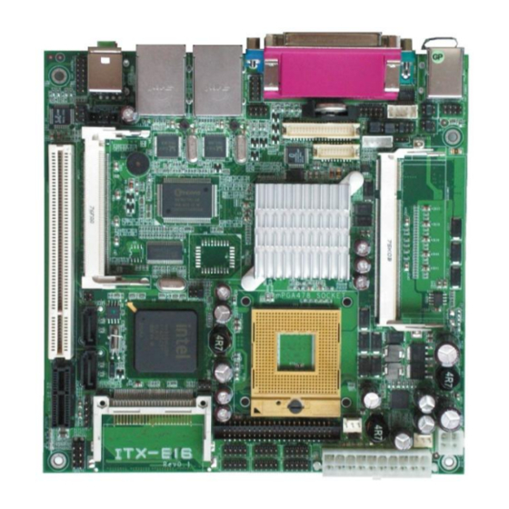
Page 17: Jumper Locations On The Itx-E16
Jumper Locations on the ITX-E16 ITX-E16 User`s Manual... -
Page 18: Jp1, Jp2, Jp3: Fsb Spd Selection
(3) Short the pin2 and pin3 for three seconds. (4) Put Jumper cap back to pin1 & 2. (5) Turn on your computer. (6) Hold Down <Delete> during boot up and enter BIOS setup to enter your preferences. COMS NORMAL CLEAR ITX-E16 User`s Manual... -
Page 19: Jp5: Cf Card Mode Selection
JP6, JP7 can be used to select the COM supple power: +5V, Ring-IN or +12V. JP6: COM1 Pin9 power or Ring-IN JP7: COM2 pin9 power or Ring-IN RING +12V JP8: COM6 Power Pin (Pin9) JP8: COM6 Pin9 power. +12V ITX-E16 User`s Manual... -
Page 20: At Mode: At Mode Selection
COM3, COM4. COM5 and COM6 support diffused RS232 protocol. The Protocols of COM2 can be set up through jumpers. COM2MODE: COM2 Protocols selection. The pin-out for each mode is illustrated on next chapter. COM2MODE1 I/F TYPE RS-232 RS-422 RS-485 ITX-E16 User`s Manual... -
Page 21: Lcdpwr: Lcd Panel Power Selection
LCDPWR can be used to select the Panel LCD supple power: +3.3V or +5V.The default setting is on +3.3V.User need to check the LCD panel spec and adjust this jumper to make Panel work in specified power rail. This Jumper serves LVDS LCD connector. LCDPWR +3.3V ITX-E16 User`s Manual... -
Page 22: Connectors On The Itx-E16
2.2 Connectors on the ITX-E16 The connectors on the ITX-E16 allow you to connect external devices such as keyboard, floppy disk drives, hard disk drives, printers and etc. The following table lists the connectors on ITX-E16 and their respective page number. -
Page 23: Connector Locations On The Itx-E16
Connector Locations on the ITX-E16 ITX-E16 User`s Manual... -
Page 24: Audio Connector
Out jack, microphone to MIC In jack. Audio sources devices like CD-ROM, walkman and etc can be connected to Lin-In jack. INT_AUDIO Connector Signal Name Pin # Pin # Signal Name LINE-IN_L LINE-IN_R LINE-OUT_L LINE-OUT_R MICI-IN_L MICI-IN_R LFE-OUT CENTER-OUT SURR-OUT_L SURR-OUT_R ITX-E16 User`s Manual... -
Page 25: Spdif Connector
SPDIF connector is for S/PDIF audio modules that allow digital instead of analog sound input or output. Signal Name Signal Name SPDIFO SPDIFI CD_IN Connector CD_IN connector is designed for wire the CD_ROM audio signals to the on-board Audio CODEC. Pin # Signal Name CD_Left CD_Right ITX-E16 User`s Manual... -
Page 26: Dio Connector
DIO_4 DIO_1 DIO_5 DIO_2 DIO_6 DIO_3 DIO_7 USB12, 34 Connectors The following table shows the pin outs of the USB12, USB34, USB56 connectors. Signal Pin # Pin # Signal Name Name N.C. USB- USB+ USB+ USB- N.C. ITX-E16 User`s Manual... -
Page 27: Int_Vga Connector
INT_VGA is for internal Video A/D board connection. The pin out is listed as below: Signal Pin # Pin # Signal Name Name GREEN BLUE HSYNC DDC_DATA VSYNC DDC_CLK SATA1.2 Connectors Pin # Signal Name SATARX+ SATARX- SATATX- SATATX+ ITX-E16 User`s Manual... -
Page 28: Vga Connector
Have a standard USB interface. Also make sure your OS supports USB controller. If your OS does not support USB controller, please contact OS vendor for possible patch or driver upgrade. For more information please contact your OS or device(s) vendors. ITX-E16 User`s Manual... -
Page 29: Lan1, 2 Gbe Connectors
System FAN Connector This is a 3-pin header for the system fan. Pin # Signal Name Ground +12V SYSPWM CPU FAN Connector This is a 3-pin header for the CPU fan. Pin # Signal Name Ground +12V CPUPWM ITX-E16 User`s Manual... -
Page 30: Lan1, 2 Gbe Leds
YELLOW Link Disconnected FLASH Packets TX/RX SPEED MODE ORANGE 1000 Mbps GREEN 100 Mbps 10 Mbps ATX_12V Power Connector The ATX_12V power connector mainly supplies power to the CPU. Caution! Pin # Signal Name ATX_12V +12V +12V ITX-E16 User`s Manual... -
Page 31: Atx_20P Connector
PSON PWROK 5VSB INT_KBMS Connector INT_KBMS is for internal input devices or MSR connection. The pin out is listed as below: Signal Name Pin # Pin # Signal Name KBDAT KBDAT KBCLK KBCLK MSDAT MSDAT MSCLK MSCLK ITX-E16 User`s Manual... -
Page 32: Ps/2 Keyboard & Mouse Connector
Mouse connector, which is mount on button of bracket. To attach PS/2 Keyboard and mouse, users need to connect trough a PS/2 1-to-2 Y-cable and plug into this Mini-Din connector. All the ITX-E16 boards come with a Y-cable. Contact with your dealer if the Y-cable is missing. Pin #... -
Page 33: Front_Panel Connector
PWR-BTN IDE Hard Disk LED Connector This connector connects to the hard drive activity LED on control panel. This LED will flash when the HDD is being accessed. IDE LED Signal Name Pin # HDDLED1 HDDLED ITX-E16 User`s Manual... -
Page 34: Tvout
Orientation is not required when making a connection to this header. RESET Signal Name RESET1 Pin # Reset Ground TVOUT Signal Name Pin # Pin # Signal Name LUMA CVBS TVGND TVGND CHOMA ITX-E16 User`s Manual... -
Page 35: Lvds Lcd Connector
+12V LCDVDD 5V/3.3V LCDVDD 5V/3.3V BCKLITE_ON BRIGHTNES LVDS_GND LVDS_GND CHB_TX0+ CHA_TX0+ CHB_TX0- CHA_TX0- LVDS_GND LVDS_GND CHB_TX1+ CHA_TX1+ CHB_TX1- CHA_TX1- LVDS_GND LVDS_GND CHB_TX2+ CHA_TX2+ CHB_TX2- CHA_TX2- LVDS_GND LVDS_GND CHB_TXC+ CHA_TXC+ CHB_TXC- CHA_TXC- LVDS_GND LVDS_GND CHB_TX3+ CHA_TX3+ CHB_TX3- CHA_TX3- ITX-E16 User`s Manual... -
Page 36: Dvi Connector
The LPT parallel port is a standard DSUB 26-pins Female connector. It can be configured as EPP or ECP or SPP mode. Signal Name Pin # Pin # Signal Name Strobe AUTOFD DATA0 ERROR DATA1 INIT SLIN DATA2 DATA3 DATA4 DATA5 DATA6 DATA7 BUSY SLCT ITX-E16 User`s Manual... -
Page 37: Cf-Ii Connector
Signal Name PDD3 PDD4 PDD5 PDD6 PDD7 PCS1- PDA2 PDA1 PDA0 PDD0 PDD1 PDD2 N.C. N.C. N.C. PDD11 PDD12 PDD13 PDD14 PDD15 PCS3- N.C. PDIOR- PDIOW- IRQ14 MST#_SLV N.C. PST1- PIORDY PDDREQ PDDACK- CF_LED- N.C. PDD8 PDD9 PDD10 ITX-E16 User`s Manual... -
Page 38: Com1 Serial Port
Pin # RS232 Mode Signal Name DCD, Data carrier detect RXD, Receive data TXD, Transmit data DTR, Data terminal ready GND, ground DSR, Data set ready RTS, Request to send CTS, Clear to send +5V,Ring-IN or +12V N.C. ITX-E16 User`s Manual... -
Page 39: Com3, 4, 5 Serial Ports
The following table shows its pin assignments. Pin # RS232 Mode Signal Name DCD, Data carrier detect RXD, Receive data TXD, Transmit data DTR, Data terminal ready GND, ground DSR, Data set ready RTS, Request to send CTS, Clear to send Ring-IN N.C. ITX-E16 User`s Manual... -
Page 40: Ide Connector
Host data 0 Host data 15 Ground Ground Host IOW Ground Host IOR Ground IOCHRDY Host PU 0 DACK Ground IRQ14 No connect Address 1 P66DET Address 0 Address 2 Chip select 1 Chip select 3 Activity LED ITX-E16 User`s Manual... -
Page 41: Chapter 3 Bios Setup
Chapter 3 BIOS Setup This chapter describes the different settings available in the Award BIOS that comes with the ITX-E16 CPU card. The topics covered in this chapter are as follows: 3.1 M ................35 3.2 S CMOS F ............ 37... -
Page 42: Bios Introduction
And the firmware chip will store the setup utility on the board. However, if you want to enter the setup after the POST, you can press Ctrl + Alt + Del simultaneously or turn off the power then back on. ITX-E16 User`s Manual... -
Page 43: Main Menu
Use this menu for basic system configuration. Advanced BIOS Features Use this menu to set the Advanced Features available on your system. Advance Chipset Features Use this menu to change the values in the chipset registers and optimize your system's performance. ITX-E16 User`s Manual... -
Page 44: Integrated Peripherals
Set Supervisor/ User Password Use this menu to set User and Supervisor Passwords. Save & Exit Setup Save CMOS value changes to CMOS and exit setup. Exit Without Saving Abandon all CMOS value changes and exit setup. ITX-E16 User`s Manual... -
Page 45: Standard Cmos Features
Video [EGA/VGA] Halt On [All , But Disk/Key] Base Memory 639K Extend Memory 1038336K Total Memory 1039360K ↑↓← → :Move Enter: Select +/-/PU/PD: Value F10:Save Esc: Exit F1:General Help F5:Previous Value F6:Fail-Safe Defaults F7:Optimized Default (Figure 2) ITX-E16 User`s Manual... - Page 46 All, but Disk/Key Base Memory Displays the amount of conventional memory detected during boot up Extended Memory Displays the amount of extended memory detected during boot up Total Memory Displays the total memory available in the system ITX-E16 User`s Manual...
-
Page 47: Ide Channel 0, 1 Master/ Slave
To auto-detect the HDD’s size, head…on this Capacity 0 MB channel Cylinder Head Precomp Landing Zone Sector ↑↓← → :Move Enter: Select +/-/PU/PD: Value F10:Save Esc: Exit F1:General Help F5:Previous Value F6:Fail-Safe Defaults F7:Optimized Default (Figure 3) ITX-E16 User`s Manual... - Page 48 Min = 0 **** Warning: Setting a value Max = 65535 of 65535 means no hard disk Landing zone Min = 0 **** Max = 65535 Sector Min = 0 Number of sectors per track Max = 255 ITX-E16 User`s Manual...
-
Page 49: Drive A/B
The system boot will not be halted for a disk error; it will stop for all other errors. All, But Disk/Key The system boot will not be halted for a key- board or disk error; it will stop for all others. (default) ITX-E16 User`s Manual... -
Page 50: Advanced Bios Features
MPS Version Control For OS [1.4] OS Select For DRAM > 64MB [Non-OS2] Report No FDD For WIN 95 [No] ↑↓← → :Move Enter: Select +/-/PU/PD: Value F10:Save Esc: Exit F1:General Help F5:Previous Value F6:Fail-Safe Defaults F7:Optimized Default (Figure 4) ITX-E16 User`s Manual... -
Page 51: Cpu Feature
The choice: 4 Min , 8 Min, 16 Min (default), 32 Min. Limit CPUID Max Val The choice: Enabled, Disabled (default). C1E Function The choice: Auto (default), Disabled Execute Disabled Bit The choice: Enabled (default), Disabled ITX-E16 User`s Manual... -
Page 52: Hard Disk Boot Priority
F1:General Help F5:Previous Value F6:Fail-Safe Defaults F7:Optimized Default (Figure 6) Bootable Add-in Cards This is for setting the priority of the hard disk boot order when the “Hard Disk” option is selected in the “[First/Second/Third] Boot Device “menu item. ITX-E16 User`s Manual... -
Page 53: Virus Warning
This field is used to enable or disable the CPU’s L3 cache. The choice: Enabled (default), Disabled. Quick Power On Self Test Allows the system to skip certain tests while booting. This will decrease the time needed to boot the system. Enabled Enable quick POST(default) Disabled Normal POST ITX-E16 User`s Manual... -
Page 54: First/Second/Third Boot Device
Boot Up Num Lock Status Selects power on state for Num Lock. The choice: On, Off (default). Gate A20 Option The choice: Normal: A pin in the keyboard controller controls GateA20. Fast (default): Lets chipset control GateA20. ITX-E16 User`s Manual... -
Page 55: Typematic Rate Setting
Sets the delay time after the key is held down before it begins to repeat the keystroke. The choice: 250 (default), 500, 750, and 1000. Typematic Delay (Msec) ….. [ ….. [ ] ….. [ ] 1000 ….. [ ] : Move Enter: Accept ESC:Abort ITX-E16 User`s Manual... -
Page 56: Security Option
OS Select For DRAM > 64MB Select OS2 only if you are running OS/2 operating system with greater than 64MB of RAM on the system. The choice: Non-OS2 (default), OS2. Report No FDD For WIN 95 The choice: No (default), Yes. ITX-E16 User`s Manual... -
Page 57: Advanced Chipset Features
TV Standard [Off] Video Connector [Automatic] TV Format [Auto] Lan1 Chip Control [Enabled] Lan2 Chip Control [Enabled] ↑↓← → :Move Enter: Select +/-/PU/PD: Value F10:Save Esc: Exit F1:General Help F5:Previous Value F6:Fail-Safe Defaults F7:Optimized Default (Figure 7) ITX-E16 User`s Manual... -
Page 58: Dram Timing Selectable
This controls the idle clocks after issuing a precharge command to DRAM. Leave this on the default setting. The choice: Auto (default), 2, 3,4,5,6. Precharge dealy (tRAS) The choice: Auto (default), 4,5,6,7,8,9,10,11,12,13,14,15. System Memory Frequency The choice: Auto (default), 533MHz, 667MHz ITX-E16 User`s Manual... -
Page 59: Slp_S4#Assertoin Width
This field shows the current DVMT mode. The choice: FIXED, DVMT (default), BOTH DVMT / FIXED Memory Size This field is used to select the graphics memory size used by DVMT/ Fixed mode. The choice: 64MB, 128MB (default), 224MB ITX-E16 User`s Manual... -
Page 60: Boot Display
Auto(defau NTSC_M NTSC_M_J NTSC_433 NTSC_N PAL_B PAL_G PAL_D PAL_H PAL_I PAL_M PAL_N PAL_60 SECAM_L SECAM_L1 SECAN_B SECAN_D SECAN_G SECAN_H SECAN_K SECAN_K1 Lan1 Chip Control The choice: Enabled (default), Disabled. Lan2 Chip Control The choice: Enabled (default), Disabled. ITX-E16 User`s Manual... -
Page 61: Integrated Peripherals
[IRQ5] Onboard Serial Port 6 [4E8] Serial Port 6 Use IRQ [IRQ7] Watch Dog Timer Select [Disabled] ↑↓← → :Move Enter: Select +/-/PU/PD: Value F10:Save Esc: Exit F1:General Help F5:Previous Value F6:Fail-Safe Defaults F7:Optimized Default (Figure 8) ITX-E16 User`s Manual... -
Page 62: On Chip Ide Device
The choice: Enabled (default), Disabled On-Chip Primary PCI IDE This field allows you to enable or disable the primary and secondary IDE controller. Select disabled if you want to add a different hard drive controller. The choice: Enabled (default), Disabled ITX-E16 User`s Manual... -
Page 63: Ide Primary/Secondary, Master/Slave Pio
The choice: Disabled, Auto (default) On-Chip Secondary PCI IDE These fields allow you to enable or disable the primary and secondary IDE controller. Select disabled if you want to add a different hard drive controller. The choice: Enabled (default), Disabled. ITX-E16 User`s Manual... -
Page 64: On-Chip Serial Ata
SATA PORT Speed Settings Disable x PATA IDE Mode Secondary x SATA Port PO, P2 is Primary ↑↓← → :Move Enter: Select +/-/PU/PD: Value F10:Save Esc: Exit F1:General Help F5:Previous Value F6:Fail-Safe Defaults F7:Optimized Default (Figure 10) ITX-E16 User`s Manual... - Page 65 SATA PORT Speed Settings Disable x PATA IDE Mode Secondary x SATA Port PO, P2 is Primary ↑↓← → :Move Enter: Select +/-/PU/PD: Value F10:Save Esc: Exit F1:General Help F5:Previous Value F6:Fail-Safe Defaults F7:Optimized Default (Figure11) ITX-E16 User`s Manual...
-
Page 66: Sata Mode
This field is used to select the function mode of the IDE connector. The only choice: Secondary: IDE serves as Secondary Master and Secondary Slave channel. SATA 1 and SATA 2 serve as Primary Master and Primary Slave channel. ITX-E16 User`s Manual... -
Page 67: Sata Mode
Help F5:Previous Value F6:Fail-Safe Defaults F7:Optimized Default (Figure13) SATA Mode Controls the SATA controller's operating mode. The choice: IDE (default), RAID, AHCI. SATA Port Speed Settings Select SATA speed. The choice: Disabled (default), Force GEN I, Force GEN II. ITX-E16 User`s Manual... -
Page 68: Sata Mode
PO, P2 is Primary ↑↓← → :Move Enter: Select +/-/PU/PD: Value F10:Save Esc: Exit F1:General Help F5:Previous Value F6:Fail-Safe Defaults F7:Optimized Default (Figure14) SATA Mode Controls the SATA controller's operating mode. The choice: IDE (default), RAID, AHCI. ITX-E16 User`s Manual... -
Page 69: Onboard Device
USB Keyboard Support Select enabled if user plan to use an USB keyboard. The choice: Enabled, Disabled (default). Azalia/AC97 Audio Select The choice: Auto (default), Azalia, AC97 Audio and Modem, AC97 Audio only, AC97 Modem only, ALL Disabled. ITX-E16 User`s Manual... -
Page 70: Super Io Device
Select an address and corresponding interrupt for the first serial ports. The choice: Disable, 3F8/IRQ4 (default), 2F8/IRQ3, 3E8/IRQ4, 2E8/IRQ3, Auto. Onboard Serial Port 2 Select an address and corresponding interrupt for the second serial ports. The choice: Disable, 3F8/IRQ4, 2F8/IRQ3 (default), 3E8/IRQ4, 2E8/IRQ3, Auto. ITX-E16 User`s Manual... -
Page 71: Uart Mode Select
Hi, Hi ……[ ] Hi, Lo ……[ ] Lo, Hi …..[ ] Lo, Lo …..[ ] : Move Enter: Accept ESC: Abort IR Transmission Delay The choice: Disabled, Enabled (default). UR2 Duplex Mode The choice: Full, Half (default). ITX-E16 User`s Manual... -
Page 72: Onboard Parallel Port
[378/IRQ7] Parallel Port Mode [SPP] x EPP Mode Select EPP1.7 x ECP Mode Use DMA PWRON After PWR-Fail [Off] ↑↓← → :Move Enter: Select +/-/PU/PD: Value F10:Save Esc: Exit F1:General Help F5:Previous Value F6:Fail-Safe Defaults F7:Optimized Default ITX-E16 User`s Manual... -
Page 73: Epp Mode Select
PWRON After PWR-Fail [Off] ↑↓← → :Move Enter: Select +/-/PU/PD: Value F10:Save Esc: Exit F1:General Help F5:Previous Value F6:Fail-Safe Defaults F7:Optimized Default EPP Mode Select Select EPP port type 1.7 or 1.9. The choice: 1.7 (default), 1.9. ITX-E16 User`s Manual... -
Page 74: Ecp Mode Use Dma
If your system supports ECP parallel port mode and you have the port set to use ECP, you must use this setting to assign a DMA channel for use by the port. The choice: DMA1, DMA3 (default). ITX-E16 User`s Manual... -
Page 75: Epp Mode Select
ECP, you must use this setting to assign a DMA channel for use by the port. The choice: DMA1, DMA3 (default). PWRON After PWR-Fail When power fails, you can select power ON or Off or Former status. The choice: Off (default), On, Former-Sts. ITX-E16 User`s Manual... -
Page 76: Onboard Serial Port 3
The choice: Disabled, 4F8, 4E8 (default). Serial Port 6 Use IRQ This is used to select an IRQ for the onboard serial port 6. The choice: IRQ3, IRQ4, IRQ5, IRQ7 (default), IRQ10, IRQ11 Watch Dog Timer Select The choice: Disabled (default), Enable ITX-E16 User`s Manual... -
Page 77: Power Management Setup
[Disabled] Secondary IDE 0 [Disabled] Secondary IDE 1 [Disabled] FDD , COM , LPT Port [Disabled] PCI PIRQ[A-D]# [Disabled] ↑↓← → :Move Enter: Select +/-/PU/PD: Value F10:Save Esc: Exit F1:General Help F5:Previous Value F6:Fail-Safe Defaults F7:Optimized Default ITX-E16 User`s Manual... -
Page 78: Pci Express Pm Function
CPUs. Inactivity period is 1 minute in each mode. User Define Set each mode individually. Select time-out periods in the section for each mode, below. Min Saving Minimum power savings. Inactivity period is 1 hour in each mode (except the hard drive). ITX-E16 User`s Manual... -
Page 79: Video Off Method
This field specifies the length of time of system inactivity while in full power on state before the computer enters suspend mode and motivates the enable 'Wake up Events in Doze & Standby' / 'PM Events'. The choice: 1Min, 2Min, 4Min, 8Min, 12Min, 20Min, 30Min, 40Min,1Hour, Disable (default). ITX-E16 User`s Manual... -
Page 80: Hdd Power Down
This field allows you to select the CPU THRM-Throttling rate. The choice: 75.0%, 50.0% (default), 25.0%. Wake-Up by PCI card Enable/Disable PCI PME wake up function. The choice: Enabled (default), Disabled. Power On by Ring Enable/Disable Power on by Ring function. The choice: Enabled (default), Disabled. ITX-E16 User`s Manual... -
Page 81: Resume By Alarm
Key in a DEC number: wwww : Move Enter: Accept ESC:Abort Primary/ Secondary IDE 0/1 When Enabled, the system will resume from suspend mode if Primary IDE 0 (1) or Secondary IDE 0 (1) is active. The choice: Enabled, Disabled (default) ITX-E16 User`s Manual... -
Page 82: Fdd, Com, Lpt Port
When Enabled, the system will resume from suspend mode if FDD, COM port, or LPT port is active. The choice: Enabled, Disabled (default). PCI PIRQ [A-D] # When Enabled, the system will resume from suspend mode if interrupt occurs. The choice: Enabled, Disabled (default). ITX-E16 User`s Manual... -
Page 83: Pnp/Pci Configuration
↑↓← → :Move Enter: Select +/-/PU/PD: Value F10:Save Esc: Exit F1:General Help F5:Previous Value F6:Fail-Safe Defaults F7:Optimized Default Init Display First This item allows you to choose which one to activate first, PCI Slot or onchip VGA. The choice: PCI Slot (default), Onboard, PCIEx. ITX-E16 User`s Manual... -
Page 84: Reset Configuration Data
[Auto] INT Pin 7 Assignment [Auto] INT Pin 8 Assignment [Auto] **PCI Express relative items** Maximum Payload Size [128] ↑↓← → :Move Enter: Select +/-/PU/PD: Value F10:Save Esc: Exit F1:General Help F5:Previous Value F6:Fail-Safe Defaults F7:Optimized Default ITX-E16 User`s Manual... -
Page 85: Irq Resource
↑↓← → :Move Enter: Select +/-/PU/PD: Value F10:Save Esc: Exit F1:General Help F5:Previous Value F6:Fail-Safe Defaults F7:Optimized Default IRQ-3,4,5,7,9,10,11,12,14,15 assigned to IRQ-3 assigned to PCI Device ….. [ Reserved ….. [ : Move Enter: Accept ESC:Abort The choice: PCI Device, Reserved. ITX-E16 User`s Manual... -
Page 86: Pci/Vga Palette Snoop
This BIOS feature determines if your graphics card should allow VGA palette snooping by a fixed function display card. The choice: Enabled, Disabled (default). INT Pin 1/2/3/4/5/6/7/8 Assignment The choice: Auto (default),3,4,5,7,9,10,11,12,14,15. Maximum Payload Size The choice: 128 (default), 256,512,1024,2048,4096. ITX-E16 User`s Manual... -
Page 87: Pc Health Status
F1:General Help F5:Previous Value F6:Fail-Safe Defaults F7:Optimized Default CPU Warning Temperature Select the CPU over-heated warning temperature. C/122F, 53C/127F, 56C/133F, The choice: Disabled (default), 50 60C/140F, 63C/145F, 66C/151F, 70C/158F. Current System Temp Show System Temperature. Current CPU Temperature Shows Board Temperature ITX-E16 User`s Manual... -
Page 88: Cpu Fan Speed
CPU FAN Speed Shows speed. CPU Fan CHASSIS Fan Speed Shows CHASSIS speed Shutdown Temperature Select the CPU over-heated shutdown temperature. C/140F, 65C/149F, 70C/158F, The choice: Disabled (default), 60 75C/167F ITX-E16 User`s Manual... -
Page 89: Frequency/Voltage Control
Load Fial-Safe Defaults (Y/N)? N ►PnP/PCI Configuration Save & Exit Setup ►PC Health Status Exit Without Saving ↑↓← → :Select Item Esc :Quit F10:Save & Exit Setup Pressing ‘Y’ loads the BIOS default values for the most stable, minimal-performance system operations. ITX-E16 User`s Manual... -
Page 90: Load Optimized Defaults
Load Optimized Default ►Integrated Peripherals Set Supervisor Password ►Power Management Set User Password ►PnP/PCI Configuration Save & Exit Setup ►PC Health Status Enter Password: Exit Without Saving ↑↓← → :Select Item Esc :Quit F10:Save & Exit Setup ITX-E16 User`s Manual... - Page 91 Features Setup Menu and its Security option. If the Security option is set to “System”, the password will be required both at boot and at entry to Setup. If set to “Setup”, prompting only occurs when trying to enter Setup. ITX-E16 User`s Manual...
-
Page 92: Save & Exit Setup
↑↓← → :Select Item Esc :Quit F10:Save & Exit Setup This allows you to exit Setup without storing in CMOS any change. The previous selections remain in effect. This exits the Setup utility and restarts your computer. ITX-E16 User`s Manual... -
Page 93: Chapter 4 Appendix
CHAPTER 4 Appendix A. I/O P ............86 DDRESS B. I (IRQ) ..........87 NTERRUPT EQUEST INES C. POST B ................88 ITX-E16 User`s Manual... -
Page 94: I/O Port Address Map
Parallel Port #1(LPT1) 360 - 36F Network Ports 3B0 - 3BF Monochrome & Printer adapter 3C0 - 3CF EGA adapter 3D0 - 3DF CGA adapter 3F0h - 3F7h Floppy Disk Controller 3F8h - 3FFh Serial Port #1(COM1) ITX-E16 User`s Manual... -
Page 95: Interrupt Request Lines (Irq)
Serial Port #1 IRQ5 Reserved IRQ6 Floppy Disk Controller IRQ7 Parallel Port #1 IRQ8 Real Time Clock IRQ9 Software Redirected to Int0Ah IRQ10 Reserved IRQ11 Reserved IRQ12 PS/2 Mouse IRQ13 80287 IRQ14 Primary IDE IRQ15 Secondary IDE ITX-E16 User`s Manual... -
Page 96: Post Beep
This beep code consists of a single long beep followed by two short beeps. The other code indicates that your DRAM error has occurred. This beep code consists of a single long beep repeatedly. ITX-E16 User`s Manual...
Need help?
Do you have a question about the ITX-E16 and is the answer not in the manual?
Questions and answers