Table of Contents
Advertisement
Quick Links
Super-mini Signal Conditioners Mini-M Series
CURRENT LOOP SUPPLY
(applicable to HART signal)
Functions & Features
• Powers a 4 – 20 mA DC current loop
• Isolates and relays HART signals
• Shortcircuit protection
• Applicable to smart transmitters
Typical Applications
• 2-wire HART transmitters
23 (.91)
76
(2.99)
124
(4.88)
mm (inch)
MODEL: M2DYH–24A–[1][2]
ORDERING INFORMATION
• Code number: M2DYH-24A-[1][2]
Specify a code from below for each [1] and [2].
(e.g. M2DYH-24A-M2/Q)
• Specify the specification for option code /Q
(e.g. /C01/S01)
SUPPLY OUTPUT
24: 24 V DC
INPUT
Current
4 – 20 mA DC (Input resistance 250 Ω)
OUTPUT
Current
A: 4 – 20 mA DC (Load resistance 600 Ω max.)
225 - 600 Ω for HART communication
[1] POWER INPUT
AC Power
M2: 100 – 240 V AC (Operational voltage range 85 – 264 V,
47 – 66 Hz)
DC Power
R: 24 V DC
SEN TRONIC
AG
Produkte, Support und Service
(Operational voltage range 24 V ±10 %, ripple 10 %p-p max.)
R2: 11 – 27 V DC
(Operational voltage range 11 – 27 V, ripple 10 %p-p max.)
P: 110 V DC
(Operational voltage range 85 – 150 V, ripple 10 %p-p max.)
[2] OPTIONS
blank: none
/Q: With options (specify the specification)
SPECIFICATIONS OF OPTION: Q (multiple selections)
COATING (For the detail, refer to M-System's web site.)
/C01: Silicone coating
/C02: Polyurethane coating
/C03: Rubber coating
TERMINAL SCREW MATERIAL
/S01: Stainless steel
GENERAL SPECIFICATIONS
Construction: Plug-in
Connection: M3 screw terminals (torque 0.8 N·m)
Screw terminal: Chromated steel (standard) or stainless
steel
Housing material: Flame-resistant resin (black)
Isolation: Input to output to power
Overrange output: Approx. -10 to +110 %
Zero adjustment: -5 to +5 % (front)
Span adjustment: 95 to 105 % (front)
SUPPLY OUTPUT
(across the terminals 1 – 5)
Output voltage: 24 – 28 V DC with no load
18 V DC min. at 20 mA
Current rating: ≤ 22 mA DC
• Shortcircuit Protection
Current limited: 30 mA max.
Protected time duration: No limit
INPUT SPECIFICATIONS
■ DC Current: Input resistor incorporated
HART COMMUNICATION
Frequency band: 500 Hz – 10 kHz (within -10 dB)
Transmission gain: Approx. -3 dB (within 1 k – 3 kHz)
measured with 250 Ω at output
Loop impedance: 250 Ω ±10 %
Communication directions: Bidirectional
Rugghölzli 2
Tel. +41 (0)56 222 38 18
CH - 5453 Busslingen
Fax +41 (0)56 222 10 12
MODEL: M2DYH
mailbox@sentronic.com
www.sentronic.com
Advertisement
Table of Contents

Related Manuals for M-system Mini-M M2DYH Series


Summary of Contents for M-system Mini-M M2DYH Series
- Page 1 /Q: With options (specify the specification) • Applicable to smart transmitters Typical Applications SPECIFICATIONS OF OPTION: Q (multiple selections) • 2-wire HART transmitters COATING (For the detail, refer to M-System's web site.) 23 (.91) /C01: Silicone coating /C02: Polyurethane coating /C03: Rubber coating TERMINAL SCREW MATERIAL (2.99)
- Page 2 MODEL: M2DYH INSTALLATION Power Consumption •AC: Approx. 3.5 VA at 100 V Approx. 5.5 VA at 200 V Approx. 6.5 VA at 264 V •DC: Approx. 3 W Operating temperature: -5 to +55°C (23 to 131°F) Operating humidity: 30 to 90 %RH (non-condensing) Mounting: Surface or DIN rail Weight: 150 g (0.33 lbs) PERFORMANCE in percentage of span...
- Page 3 MODEL: M2DYH SCHEMATIC CIRCUITRY & CONNECTION DIAGRAM HART Isolation DC Isolation Output 4–20mADC Driver INPUT 250Ω OUTPUT – – 2-WIRE XMTR PWR SUPPLY 24V DC Supply HART Isolation U(+) POWER V(–) Base Socket *Hand-held communicator ■ When Used as DC Supply ■...
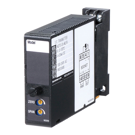
- Page 4 MODEL (applicable to HART signal) BEFORE USE ..COMPONENT IDENTIFICATION Thank you for choosing M-System. Before use, please check Body Base Socket contents of the package you received as outlined below. If you have any problems or questions with the product, please contact M-System’s Sales Office or representatives.
- Page 5 M2DYH CHECKING ADJUSTMENT PROCEDURE 1) Terminal wiring: Check that all cables are correctly con- This unit is calibrated at the factory to meet the ordered nected according to the connection diagram. specifications, therefore you usually do not need any cali- 2) Power input voltage: Check voltage across the terminal bration.
Need help?
Do you have a question about the Mini-M M2DYH Series and is the answer not in the manual?
Questions and answers