Table of Contents
Advertisement
Quick Links
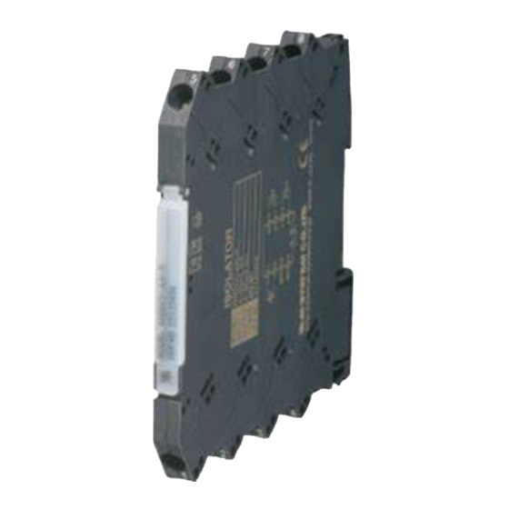
Euro Terminal Ultra-Slim Signal Conditioners M6D Series
THERMOCOUPLE ALARM
(PC programmable)
Functions & Features
• 5.9-mm wide ultra-slim design
• Low profile allows the M6D module mounted in a 120-mm
deep panel
• Provides a relay contact output at preset DC input levels
• PC programmable
• Linearization and upscale and downscale burnout
protection
• High-density mounting
• Power and status indicator LEDs
5.9 (.23)
94
(3.70)
102
(4.02)
mm (inch)
MODEL: M6DXAT–[1]–R
ORDERING INFORMATION
• Code number: M6DXAT-[1]-R
Spacify a code from below for [1].
(e.g. M6DXAT-2-R)
• Temperature range (e.g. 0 – 1000°C)
[1] INPUT THERMOCOUPLE
1: (PR)
2: K (CA)
3: E (CRC)
4: J (IC)
5: T (CC)
6: B (RH)
7: R
8: S
N: N
0: Specify (Please provide a emf table.)
(Configurator software is used to change the input type and
precise range.)
SEN TRONIC
AG
Produkte, Support und Service
OUTPUT
Relay; SPDT or transfer contact
POWER INPUT
DC Power
R: 24 V DC
(Operational voltage range 24 V ±10 %, ripple 10 %p-p max.)
RELATED PRODUCTS
• PC configurator software (model: M6CFG)
Downloadable at M-System's web site.
A dedicated cable is required to connect the module to the
PC. Please refer to the internet software download site or
the users manual for the PC configurator for applicable
cable types.
GENERAL SPECIFICATIONS
Connection
Input and output: Euro terminal (torque 0.3 N·m)
Power input: Via the Installation Base (model: M6DBS)
or Euro terminal (torque 0.3 N·m)
Applicable wire size: 0.2 to 2.5 mm
Housing material: Flame-resistant resin (black)
Isolation: Input to output to power
Burnout: Upscale standard; downscale or no burnout
optional by programming
In case of upscale standard, the alarm operates as if the
input signal has exceeded over the range.
Linearization: Standard
Cold Junction Compensation: CJC sensor incorporated
Power LED: Green light turns on when the power is supplied.
Status indicator LED: Orange LED; Flashing patterns
indicate different operating status of the transmitter.
Alarm monitor LED: Red LED turns on when the alarm is
tripped.
Programming: Downloaded from PC
Input type and range
Input fine adjustments
User's Thermocouple table
Burnout (Upscale, downscale or no burnout)
Alarm setpoint (input %)
Trip action (High or Low)
Relay coil (energized or de-energized)
Power ON delay time (0 to 999 sec.)
Alarm ON delay time (0 to 999 sec.)
Hysteresis (deadband) (input %)
Alarm test, and others
Configurator connection: 2.5 dia. miniature jack;
RS-232C level
Factory default setting
Alarm setpoint: 80 %
Rugghölzli 2
Tel. +41 (0)56 222 38 18
CH - 5453 Busslingen
Fax +41 (0)56 222 10 12
MODEL: M6DXAT
2
mailbox@sentronic.com
www.sentronic.com
Advertisement
Table of Contents

Related Manuals for M-system M6D Series


Summary of Contents for M-system M6D Series
- Page 1 MODEL: M6DXAT OUTPUT Euro Terminal Ultra-Slim Signal Conditioners M6D Series Relay; SPDT or transfer contact THERMOCOUPLE ALARM POWER INPUT (PC programmable) Functions & Features DC Power • 5.9-mm wide ultra-slim design R: 24 V DC • Low profile allows the M6D module mounted in a 120-mm (Operational voltage range 24 V ±10 %, ripple 10 %p-p max.)
-
Page 2: Input Specifications
MODEL: M6DXAT Trip action: High PERFORMANCE in percentage of span Relay coil at alarm: Energized Setpoint accuracy (trip point accuracy): Power ON delay time: 5 sec. Accuracy in Table 1 + Cold junction compensation error Alarm ON delay time: 0 sec. Cold junction compensation error: Hysteresis (deadband) : 1.0 % ±3°C at 25 ±10°C... -
Page 3: External View
MODEL: M6DXAT Pollution Degree 2 Max. operating voltage 250 V (relay output circuit) Input or power to output: Reinforced insulation Input to power: Basic insulation EXTERNAL VIEW (With the cover open) Power LED Alarm Monitor LED Status Indicator LED Configurator Jack DIMENSIONS unit: mm (inch) WIRE INSERTION ANGLE: approx. - Page 4 MODEL: M6DXAT SCHEMATIC CIRCUITRY & CONNECTION DIAGRAM STATUS ALARM SENSOR MONITOR LED comp. leadwire Digital Computation Low Drift OUTPUT Amplifier – POWER LED POWER JACK CONFIGURATOR – POWER I Relay Protection • AC Powered • DC Powered Inductive Inductive Load (Coil) Load (Coil) LOAD LOAD...
- Page 5 (PC programmable) BEFORE USE ..POINTS OF CAUTION Thank you for choosing M-System. Before use, please check ■ CONFORMITY WITH EC DIRECTIVES contents of the package you received as outlined below. • The relay output circuit is suitable for use in Pollution De-...
-
Page 6: Component Identification
M6DXAT COMPONENT IDENTIFICATION INSTALLATION Set the unit so that its DIN rail adapter is at the bottom. When the unit is installed to an Installation Base (model Body M6DBS), refer to its instruction manual. ■ MOUNTING THE UNIT ON A DIN RAIL A) Hang the upper hook at the rear side of unit on the DIN rail. -
Page 7: Terminal Connections
M6DXAT TERMINAL CONNECTIONS Connect the unit as in the diagram below or refer to the connection diagram on the side of the unit. ■ EXTERNAL DIMENSIONS unit: mm (inch) WIRE INSERTION ANGLE: approx. 7° 8–M3 EURO TERMINAL DIN RAIL HOOK DIN RAIL 35mm wide SCREWDRIVER... -
Page 8: Maintenance
M6DXAT CHECKING MAINTENANCE 1) Terminal wiring: Check that all cables are correctly con- Regular calibration procedure is explained below: nected according to the connection diagram. 2) Power input voltage: Check voltage across the terminal ■ CALIBRATION 7– 8 with a multimeter. Warm up the unit for at least 10 minutes.
Need help?
Do you have a question about the M6D Series and is the answer not in the manual?
Questions and answers