
Related Manuals for Bromic Heating SMART-HEAT LINK

Summary of Contents for Bromic Heating SMART-HEAT LINK
- Page 1 BROMIC SMART-HEAT LINK HOME AUTOMATION INSTALLATION INSTRUCTIONS IMPORTANT READ THIS MANUAL CAREFULLY. SEE INSIDE COVER FOR IMPORTANT INFORMATION ABOUT THIS MANUAL. KEEP INSTRUCTION WITH APPLIANCE FOR FUTURE REFERENCE. Version 3.0 AU...
- Page 2 IMPORTANT This manual contains important information about the installation, and operation of Bromic Smart-Heat Link. Please pay close attention to the important safety information shown throughout this instruction manual. Any safety information will be accompanied by the following safety alert symbols: DANGER WARNING IMPORTANT...
-
Page 3: Table Of Contents
CONTENTS IMPORTANT NOTES & WARNINGS GETTING STARTED TECHNICAL SPECIFICATIONS INSTALLATION & OPERATION 6 - 11 SUPPLEMENTARY INFORMATIONS INSTALLATION INSTRUCTION TROUBLESHOOTING bromic.com... -
Page 4: Important Notes & Warnings
IMPORTANT NOTES AND WARNINGS WARNING • This device must only be used on a 5 Volt DC electrical supply. Correct polarity must be used or the device will be damaged. • Read all instructions before installing or using this • This controller is NOT intended to be installed on device. -
Page 5: Getting Started
GETTING STARTED Integration must be performed by a Home Automation Integrator or licenced technician with software and communication debugging experience. You will need the following from Bromic - Bromic Smart-Heat Link device (for Bromic Part Numbers refer to table on next page) - Bromic Heater controller (ON/OFF or Dimmer) supplied with pre-programmed paired remote control and installed by licenced electrical contractor. -
Page 6: Technical Specifications
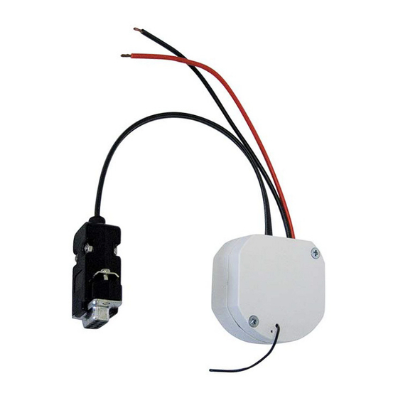
TECHNICAL SPECIFICATION Model Bromic Smart-Heat Link Part no. For AU P/N: 2620279 For US/CA P/N: BH3130097 For EU P/N: BH3130098 Power Supply 5VDC Carrier frequency US/CA/AU 916 MHz, EU 868 MHz Transmission Range to 30m or 100 feet Controller Working temperature -10°C to +55°C (14°F to 131°F) INSTALLATION INSTRUCTIONS SETTING UP... - Page 7 PROGRAMMING INSTRUCTIONS STEP 1 – Connection of devices Wire the Bromic Smart-Heat Link to a 5VDC supply, by connecting the RED (+) and BLACK (-) wires ensuring correct polarity. 5VDC adaptor and RS232 cable/RS232 convertor are not supplied byBromic. TO BE INSTALLED BY HOME INTEGRATOR Power input lead Black: Ground Red: 5VDC...
- Page 8 PROGRAMMING INSTRUCTIONS © Instructions are based on Docklight but any other product with RS232 debugging reading and writing features can be used. Docklight© Disclaimer: Refer to http:\www.docklight.de for more information. Docklight© is a 3rd party software tool developed by Flachmann und Heggelbacher with no association with Bromic. Refer to the software end licence agreement before downloading and choosing to use this software tool.
- Page 9 PROGRAMMING INSTRUCTIONS STEP 4 – Setting up the button codes in Docklight. The Smart-Heat Link device can operate up to 50 controllers using pre-program codes. The codes are stored in memory ID location 1 – 50. The following example uses ID location 1. Refer to section “Additional Codes” for further examples and defining additional commands.
- Page 10 PROGRAMMING INSTRUCTIONS Click ok and repeat the process for all button commands. STEP 5 – Programming the controller Ensure power is on to the Controller by checking the operation with the remote. Open the remote cover by inserting flat screwdriver into bottom recess left and right side tabs.
- Page 11 PROGRAMMING INSTRUCTIONS Note: The following operations must be performed within working range to the controller. 1. Press the P3 button on the remote - this sets the controller into learn function. 2. A continuous audible sound will be heard from the controller (if in audible range of the controller).
-
Page 12: Supplementary Informations
PROGRAMMING INSTRUCTIONS CODE STRUCTURE AND ADDITIONAL CODES The code structure for transmit codes is as listed below 7 Button 4 Button Button Function Function Transmit Code Transmit Code Transmit Code (Dimmer (ON/OFF ID Location 3 ID Location 4 ID Location 2 Controller) Controller) 1 -1 00%... -
Page 13: Installation Instruction
INSTALLATION INSTRUCTIONS TO HOME AUTOMATION SYSTEM Now that all remote functions have been programmed into the Bromic Smart-Heat Link device, the RS232 connection can be made to the Home Automation System. Your Home Automation System Integrator is required to perform this operation and program the codes and button functions into the Home Automation Interface. -
Page 14: Troubleshooting
TROUBLESHOOTING It is recommended that all button operations are confirmed using the device connected to a PC before integration of commands to a Home Automation System. The Docklight command window is a useful tool to confirm the Bromic Smart-Heat Link is ©... - Page 15 TROUBLESHOOTING Symptom Cause Resolution Command not Device is not on Check power to device is ON working Check power to controller is ON Check remote control operates controller functions Device is not plugged Check RS232 connection working with PC into RS232 first, then debug RS232 on Home automation system Device transmission out...
Need help?
Do you have a question about the SMART-HEAT LINK and is the answer not in the manual?
Questions and answers