Table of Contents
Advertisement
Quick Links
Advertisement
Table of Contents

Related Manuals for Hikmicro Raptor Series


Summary of Contents for Hikmicro Raptor Series
- Page 1 Thermal Binocular HIKMICRO Raptor Series User Manual...
- Page 2 INTERRUPTION, OR LOSS OF DATA, CORRUPTION OF SYSTEMS, OR LOSS OF DOCUMENTATION, WHETHER BASED ON BREACH OF CONTRACT, TORT (INCLUDING NEGLIGENCE), PRODUCT LIABILITY, OR OTHERWISE, IN CONNECTION WITH THE USE OF THE PRODUCT, EVEN IF HIKMICRO HAS BEEN ADVISED OF THE POSSIBILITY OF SUCH DAMAGES OR LOSS.
- Page 3 Thermal Binocular User Manual ABUSES. IN THE EVENT OF ANY CONFLICTS BETWEEN THIS MANUAL AND THE APPLICABLE LAW, THE LATTER PREVAILS.
- Page 4 Thermal Binocular User Manual Regulatory Information FCC Information Note: This product has been tested and found to comply with the limits for a Class B digital device, pursuant to Part 15 of the FCC Rules. These limits are designed to provide reasonable protection against harmful interference in a residential installation.
- Page 5 Thermal Binocular User Manual Directive 2012/19/EU (WEEE Directive): Products marked with this symbol cannot be disposed of as unsorted municipal waste in the European Union. For proper recycling, return this product to your local supplier upon the purchase of equivalent new equipment, or dispose of it at designated collection points. For more information see: www.recyclethis.info According to the Waste Electrical and Electronic Equipment Regulations 2013:...
- Page 6 Thermal Binocular User Manual dans un autre environnement. B 급 기기 : 이 기기는 가정용 (B 급 ) 전자파적합기기로써 주로 가정에서 사용하는 것을 목적으로 하며 , 모든 지역에서 사용할 수 있습니다 .
- Page 7 Thermal Binocular User Manual Symbol Conventions The symbols that may be found in this document are defined as follows. Symbol Description Indicates a hazardous situation which, if not avoided, will or could Danger result in death or serious injury. Indicates a potentially hazardous situation which, if not avoided, Caution could result in equipment damage, data loss, performance degradation, or unexpected results.
- Page 8 Thermal Binocular User Manual Safety Instruction These instructions are intended to ensure that user can use the product correctly to avoid danger or property loss. Laws and Regulations ● Use of the product must be in strict compliance with the local electrical safety regulations. Transportation ●...
- Page 9 Thermal Binocular User Manual ● If the equipment is used in a manner not specified by the manufacturer, the protection provided by the device may be impaired. ● It is recommended to reboot the device every 2 hours when using it to ensure the device performance.
-
Page 10: Table Of Contents
Thermal Binocular User Manual Table of Contents Chapter 1 Overview ........................1 1.1 Device Description ......................1 1.2 Main Function ........................1 1.3 Appearance ........................1 Chapter 2 Preparation ........................4 2.1 Cable Connection ......................4 2.2 Install Battery ........................4 2.3 Power On/Off ........................ - Page 11 Thermal Binocular User Manual Chapter 4 Burning Prevention ...................... 15 Chapter 5 Hot Tracking ......................... 16 Chapter 6 Measure Distance ......................17 Chapter 7 Geographic Location Display ..................18 Chapter 8 Direction Display ......................19 8.1 Calibrate Compass ......................19 8.2 Magnetic Declination Correction ..................
-
Page 12: Chapter 1 Overview
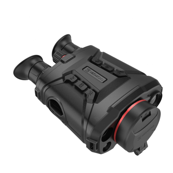
Chapter 1 Overview 1.1 Device Description HIKMICRO RAPTOR series is a powerful and innovative handheld thermal and digital night vision binocular which adopts a 12μm infrared thermal sensor with NETD < 20mK sensitivity, 2560 × 1440 low illumination optical sensor with built-in adjustable IR illuminator, and a precise built-in laser rangefinder up to 1000 m measuring distance. - Page 13 Thermal Binocular User Manual Figure 1-1 Device Appearance Table 1-1 Buttons and Components Description Function Lens Cover Protect the lens. The eye end of the device. You can view target from this Eyepiece part. Focus Ring Adjust focus to obtain clear targets. ●...
- Page 14 Thermal Binocular User Manual Description Function ● Press to switch day/night/defog/auto mode. Mode Key ● Hold: Trigger FFC. ● Press: Measure distance with laser for once. Laser Key ● Hold: Measure distance with laser for continuously. ● Press: Capture snapshots. Capture Key ●...
-
Page 15: Chapter 2 Preparation
Thermal Binocular User Manual Chapter 2 Preparation 2.1 Cable Connection Connect the device and power adaptor with a type-C cable to power on the device. Alternatively, connect the device and PC to export files. Figure 2-1 Cable Connection 2.2 Install Battery Insert the batteries into the battery compartment. - Page 16 Thermal Binocular User Manual Figure 2-2 Loosen Knob 2. Take out the detachable battery compartment, and install the batteries as the positive and negative marks indicate. Figure 2-3 Install Batteries 3. Install the battery compartment back, and rotate the battery compartment cover clockwise to lock it.
-
Page 17: Power On/Off
Thermal Binocular User Manual ● Charge the batteries with the supplied battery charger for more than 4 hours before first use. ● The battery type is 18650 with the protection board, and the battery size should be within 19 mm × 70 mm. The rated voltage and capacity are 3.6 VDC/3.2 Ah. 2.3 Power On/Off Power On When the battery is sufficiently charged, hold... -
Page 18: Chapter 3 Image Settings
Thermal Binocular User Manual Chapter 3 Image Settings 3.1 Adjust Diopter Steps 1. Power on the device. 2. Hold the device and make sure the eyepiece covers your eye. 3. Adjust the diopter adjustment ring until the OSD text or image is clear. Figure 3-1 Adjust Diopter Note When adjusting diopter, DO NOT touch the surface of lens to avoid smearing the lens. -
Page 19: Adjust Brightness
Thermal Binocular User Manual Figure 3-2 Adjust Focus Note When adjusting focus, DO NOT touch the surface of lens to avoid smearing the lens. 3.3 Adjust Brightness In the menu mode, select and press to adjust brightness. In white hot mode, the higher the value of brightness is, the brighter the image is. -
Page 20: Set Picture In Picture
Thermal Binocular User Manual 2. Select and press to switch scene. – refers to recognition mode and is recommended in normal scene. – refers to jungle mode and is recommended in hunting environment. 3. Hold to save settings and exit. 3.6 Set Picture in Picture Hold in live view mode to enable PIP, and hold... - Page 21 Thermal Binocular User Manual 6. Press in live view interface to switch the selected palettes. Optical The image of optical channel is displayed in this mode. White Hot The hot part is light-colored in view. The higher the temperature is, the lighter the color is. Black Hot The hot part is black-colored in view.
- Page 22 Thermal Binocular User Manual Red Hot The hot part is red-colored in view. The higher the temperature is, the redder the color is. Fusion From high temperature to low temperature, the image is colored in from white, yellow, red, pink to purple. Image Fusion Fuse the optical image with the thermal image.
-
Page 23: Set Display Mode
Thermal Binocular User Manual 3.8 Set Display Mode You can select different display modes in different scenes. Press in live view interface to switch display modes. Day, night, defog, and auto are selectable. : Day mode. You can use this mode at daytime and in bright environment. In day mode, the IR light is off automatically. -
Page 24: Flat Field Correction
Thermal Binocular User Manual interface. ● When the menu or OSD blocks the defective pixel, the menu at the bottom can be hidden, and the menu at the upper left can be mirrored to the upper left of the interface. 3.11 Flat Field Correction This function can correct non-uniformity of display. -
Page 25: Adjust Digital Zoom
Thermal Binocular User Manual 2. Select 3. Press to enable this function. 4. Hold to return to the live view interface, and view the target. Result The details of the whole live view image will be enhanced. 3.14 Adjust Digital Zoom You can zoom the image by using this function. -
Page 26: Chapter 4 Burning Prevention
Thermal Binocular User Manual Chapter 4 Burning Prevention This function can prevent the detector of the thermal channel from being burned. When you enable this function, the shield will close if the grey scale of the detector reaches a certain value. Steps 1. -
Page 27: Chapter 5 Hot Tracking
Thermal Binocular User Manual Chapter 5 Hot Tracking The device can detect the highest temperature spot in the scene and mark it on display. Steps 1. Hold to show the menu. 2. Select and press to mark the spot of highest temperature. 3. -
Page 28: Chapter 6 Measure Distance
Thermal Binocular User Manual Chapter 6 Measure Distance The device can detect the distance between the target and the observation position with laser. Before You Start When measuring the distance, keep the hand and the position steady. Otherwise, the accuracy may be affected. -
Page 29: Chapter 7 Geographic Location Display
Thermal Binocular User Manual Chapter 7 Geographic Location Display Equipped with satellite positioning modules, the device is able to display the longitude and latitude, as well as the sea level altitude of the device on the live image, captured images, and recorded videos. -
Page 30: Chapter 8 Direction Display
Thermal Binocular User Manual Chapter 8 Direction Display Equipped with a compass, the device is able to display its direction on the live image, captured images, and recorded videos. In menu mode, select and press to enable the compass modules, then follow the pop-up instructions to calibrate the compass. -
Page 31: Magnetic Declination Correction
Thermal Binocular User Manual ● Calibration Level indicates the validity of calibration. Higher level means more accurate compass reading. Calibration succeeds when the Calibration Level turns to 3. 3. Stop moving the device when calibration success message pops up. Result The direction information is displayed on the up right of the live view image. -
Page 32: Chapter 9 Picture And Video
Thermal Binocular User Manual Chapter 9 Picture and Video You can manually record video or capture picture when displaying live view. 9.1 Capture Picture In live view mode, press to capture picture. Note When capturing succeeds, the image freezes for 1 second and a prompt shows on the display. For exporting captured pictures, refer to Export Files. -
Page 33: View Local Files
Thermal Binocular User Manual loud noise in the video, you can disable this function. Steps 1. Hold to show the menu. 2. Select 3. Press to enable or disable this function. 4. Hold to save and exit. 9.4 View Local Files Captured images and recorded videos are automatically stored in the device, and you can view the files in local albums. - Page 34 Thermal Binocular User Manual before other operations. ● Remove batteries from the device before connecting to your PC, or it may cause device damage. Steps 1. Connect the device and PC with cable. Note Make sure the device is turned on when connecting the cable. 2.
-
Page 35: Chapter 10 Client Software Connection
● Hotspot Name: HIK-IPTS Serial No. ● Hotspot Password: Serial No. 4. Search the HIKMICRO Sight App on App Store (iOS System) or Google Play™ (Android System) to download it, or scan the QR code to download and install the app. -
Page 36: Chapter 11 Cvbs Output
Thermal Binocular User Manual Chapter 11 CVBS Output The CVBS output is used to debug the device. You can also view the device image on the display unit for details. Before You Start Connect the device to the display unit via CVBS interface of the aviation plug. Steps 1. -
Page 37: Chapter 12 System Settings
Thermal Binocular User Manual Chapter 12 System Settings You can set unit, time, and language for your device. 12.1 Synchronize Time Steps 1. Hold to show the menu. 2. Select , and press to enter the time setting interface. 3. Press to switch the time system, and press to select the time and date to be synchronized. -
Page 38: Chapter 13 Maintenance
Thermal Binocular User Manual Chapter 13 Maintenance This part introduces the operation of checking device information, upgrading device, and restoring to defaults, etc. 13.1 View Device Information Steps 1. Hold to show the menu of device. 2. Select , and press . -
Page 39: Chapter 14 Frequently Asked Questions
Thermal Binocular User Manual Chapter 14 Frequently Asked Questions 14.1 Why is the monitor off? Check whether the device is off-battery. Check the monitor after charging the device for 5 minutes. 14.2 The image is not clear, how to adjust it? Adjust the diopter adjustment knob until the image is clear. -
Page 40: Chapter 15 Appendix
Chapter 15 Appendix 15.1 Device Command Scan the following QR code to get device common serial port commands. Note that the command list contains the commonly used serial port commands for HIKMICRO thermal cameras. 15.2 Device Communication Matrix Scan the following QR code to get device communication matrix. - Page 41 UD30627B-A...
Need help?
Do you have a question about the Raptor Series and is the answer not in the manual?
Questions and answers