Advertisement
Available languages
Available languages
Quick Links
G e n e r a l i n f o r m a t i o n :
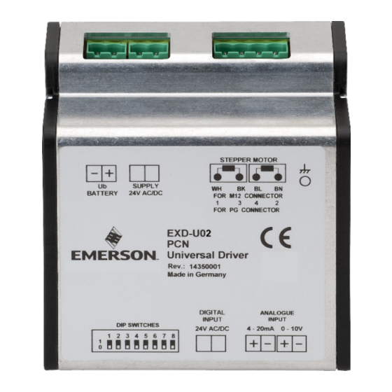
EXD-U02 Universal Driver Module is for driving Emerson stepper motor driven
electrical control valves series EX4-8 and CV4-7. Typical application of EXD-U02
in a CO
booster transcritical system is shown in Fig. 8.
2
S a f e t y i n s t r u c t i o n s :
• Read operating instructions thoroughly. Failure to comply can result in device
failure, system damage or personal injury
• According to EN 13313 it is intended for use by persons having the
appropriate knowledge and skill.
• Before wiring disconnect all voltages from system and device.
• Do not operate system before all cable connections are completed.
• Do not apply 110/220/230V to any terminal of driver module.
• Entire electrical connections have to comply with local regulations.
I n s t a l l a t i o n :
• EXD-U02 delivery is in two versions: as standalone or as kit with K09-U00
electrical terminal.
• Mount all electrical terminals. Electrical
terminal for analogue signal connection is
different to other terminals in term of size and fit
only on location (#6) as Fig. 3/4. The small
terminals require smaller size of screw driver
compared to other terminals.
• EXD-U02 is delivered with bracket suitable for
mounting on DIN-Rail. Hang driver above DIN-
Rail and push down- and backward until it snaps
completely and hold by DIN-Rail.
W i r i n g :
• Wiring diagram for single driver with optional backup battery ECP-024 see Fig. 3.
Single ECP-024 can be connected to two EXD-U02 see Fig. 4
• It is recommended the use of prewired M12 plug and cable assembly (EXV-Mxx)
for easy wiring between EX4-8 or CV4-7 and EXD-U02. The wires colors match
to colors coding of stepper motor terminals (see Fig.3 & 4).
• 24VAC digital input (#1, Fig 3 & 4) can be supplied from same source of power.
Digital input act as ON/OFF command and it is only method to make sure valve
is fully closed. The digital input can be controlled by potential free contact(s).
As illustrated, external contact "C" is a normally open contact and the
activation/deactivation is in general parallel with compressor ON/OFF. Additional
external contact "P" as normally close in series with contact "C" can be used for
pump down function.
• It is mandatory the external grounding backside of EXD-U02 (Fig.2).
• Use a class II category transformer (#2) for 24 VAC power supply. Do not ground
the 24 VAC line and install proper size of fuse (#3)
• Keep separate the wires for power supply, stepper motor of valve and signal.
• Recommended wire size Ø 0.5 ... 2.5 mm
Special wiring for two valves/drivers from single source of analog input (Fig.4):
• Two valves operating simultaneously in parallel. It is intended for application that
both valves are synchronized, equally opening or closing. In case of 4-20mA
analog signal, see Fig.5a and in case of 0-10V signal, see Fig.5b.
D i p s w i t c h e s s e t t i n g ( F i g . 6 ) :
Disconnect power supply as well as analog input signal. Set dip switches by a pencil
or similar according table 1. The dip switches of new EXD-U02 are all set to OFF
position (OFF: Downward / ON: Upward).
1
Valve type/ step
recovery /analog input
EX4-6
OFF
CV4
OFF
CV5-6
OFF
EX7
OFF
CV7
OFF
EX8
OFF
Step Recovery – Yes
-
Step Recovery – No
-
Signal: 4-20 mA
-
Signal: 0-10V
-
Table 1
Emerson Climate Technologies GmbH
Am Borsigturm 31 I 13507 Berlin I Germany
Universal Driver Module EXD-U02
for Electrical Control Valves EX4-8 / CV4-7
Fig.1
Fig.2
2
.
Dip Switch Number
2
3
4
5
6
Dip switch position
OFF
OFF
ON
OFF
OFF
OFF
ON
OFF
OFF
OFF
OFF
ON
ON
OFF
OFF
ON
OFF
OFF
OFF
OFF
ON
OFF
ON
OFF
OFF
ON
ON
OFF
OFF
OFF
-
-
-
-
-
-
-
-
-
-
-
-
-
-
-
-
-
-
-
-
https://climate.emerson.com/en-gb
Operating instructions
V a l v e S y n c h r o n i z a t i o n :
• The EXD-U02 synchronizes the stepper motor driven valve with the Mechanical
reference point in the fully closed position when the digital input is interrupted for
minimum time shown in the table 2.
S t e p R e c o v e r y f u n c t i o n :
• Step Recovery enables to recover potentially lost steps during operation if the
digital input has not been interrupted for a continuous operation (for more detail
see technical bulletin of EXD-U02
Warning:
• Minimum analog signal (0VDC in case of 0-10VDC or 4 mA in case of 4-
20 mA) is not intended for driving valve to fully close position. Only digital
input interruption is the appropriate command for driving valve to fully close
position.
S t a r t - u p p r o c e d u r e :
• Note: EX/CV valves are delivered in partially open position.
• Vacuum the entire refrigeration circuit. The valve can be driven to close position
before charging the system. In order to close the valve fully, disconnect the Digital
input while keeping the 24VAC supply voltage connected for a period of time as
shown in table 2.
Valve
EX4-6
EX7
EX8
Table 2
T e c h n i c a l d a t a :
Power supply
Note: 24 VDC supply voltage can be used but it results to lower MOPD and
it needs to be verified/approved under system manufacturer responsibility.
Inputs
Outputs
Uninterruptible power
supply ECP-024
Wiring Diagram
(#1)
Digital input terminals/signal (0 V = OFF; 24 V = ON)
(#2)
Transformer
(#3)
Fuse
(#4)
Plug cable assembly EXV-Mxx for connection to EX4-8 / CV4-7
Cable color code:
(#5)
Third party controller's analog signal supplies (4...20 mA or 0...10 V)
(#6)
Analog input terminal/signal (4...20 mA or 0...10 V)
(#7)
Optional Uninterruptible Power Supply insures the closure of valve during
power failure in system.
(#8) Terminal (EXD-U02 /ECP-024) to be connected to single source. In event of power
interruption, ECP-024 drive automatically the valve(s) to close position.
(C)
Normally open external potential free contact.
Function: Interruption of digital input for synchronization purpose or fully closing
the valve.
(P)
Normally close external potential free contact
(Pump down function)
Dimensions
Marking
7
8
-
-
-
-
-
-
-
-
-
-
-
-
OFF
-
ON
-
-
OFF
-
ON
Date: 26.11.2019
Closing time (sec.)
Valve
2...5
CV4-6
4...5
CV7
6...8
-
Analog input 4...20 mA, burden 364 Ω,
Analog input 0...10 V, impedance 24 kΩ.
Digital input: 24 VAC/DC (+10%, -15%), 50-60 Hz
Current outputs for stepper motor of EX4-8/ CV4-7
Required power supply voltage: 24 VAC ± 10%
Outputs: two individual, each +18 VDC
(see Fig. 3,4,5a,5b)
WH=White
BK=Black
BL= Blue
BN=Brown
EXD-U02_OI_ML_R03_866919.docx
Closing time (sec.)
2...5
13...15
-
24 VAC ±10%, 50-60 Hz
or
See Fig.7
Advertisement

Related Manuals for Emerson EXD-U02


Summary of Contents for Emerson EXD-U02
- Page 1 Disconnect power supply as well as analog input signal. Set dip switches by a pencil Dimensions See Fig.7 or similar according table 1. The dip switches of new EXD-U02 are all set to OFF Marking position (OFF: Downward / ON: Upward).
- Page 2 U02 angeschlossen werden: siehe Fig.4. Tabelle 2 • Für eine einfache Verdrahtung zwischen EX4-8 / CV4-7 und EXD-U02 wird die T e c h n i s c h e D a t e n : Verwendung von vorverdrahteten M12-Steckern mit Kabel (EXV-Mxx) Versorgungs- empfohlen.
- Page 3 à l’aide d’un crayon ou équivalent selon la table 1. Les commutateurs Fonction: Interruption du signal d’entrée digital pour la synchronisation ou d’un nouvel EXD-U02 sont tous en position OFF (OFF: vers le bas / ON: vers le la fermeture complète de la vanne.
- Page 4 • El driver EXD-U02 sincroniza la válvula sobre la posición totalmente cerrada de las series EX4-8 y CV4-7. La aplicación típica de EXD-U02 en un circuito booster cuando la entrada digital se interrumpe por un espacio de tiempo mínimo según de CO2, se muestra en la Fig.
- Page 5 Fig.7 Disconnettere l'alimentazione e il segnale di ingresso analogico. Impostare i dip switch con una matita (o simile) come in tabella 1. I dip switch del nuovo EXD-U02 Marchio sono tutti in posizione OFF (OFF: Downward / ON: Upward).
- Page 6 • Схема подключения привода с дополнительной батареей ECP-024 см. на 1 Цифровой вход: 24 В (+10%, -15%), переменного/ Рис. 3. Одна ECP-024 может присоединяться к двум EXD-U02 – см. Рис. 4 постоянного тока, 50-60 Гц. • Рекомендуется использовать разъём M12 и кабельную сборку EXV-Mxx для...
- Page 7 EXD-U02 Fig./ Рис. 3 Fig./ Рис. 4 Fig./ Рис. 5a Fig./ Рис. 5b Emerson Climate Technologies GmbH https://climate.emerson.com/en-gb Am Borsigturm 31 I 13507 Berlin I Germany Date: 26.11.2019 EXD-U02_OI_ML_R03_866919.docx...
- Page 8 Valvola Bypass Valvola recupero calore Valvola di espansione aspirazione Газовый клапан Клапан для рекуперации Регулятор давления в Байпасный клапан Расширительный клапан высокого давления тепла испарителе Emerson Climate Technologies GmbH https://climate.emerson.com/en-gb Am Borsigturm 31 I 13507 Berlin I Germany Date: 26.11.2019 EXD-U02_OI_ML_R03_866919.docx...
Need help?
Do you have a question about the EXD-U02 and is the answer not in the manual?
Questions and answers