Table of Contents
Advertisement
Quick Links
O
P
O
P
C C
h h
a a
n n
g g
z z
h h
o o
u u
E E
C
h
a
n
g
z
h
o
u
E
A A
d d
d d
: : No.1, North Qiyang Road, Tianning District, Changzhou, Jiangsu
A
d
d
:
E
R
A
T
I
O
E
R
A
T
I
O
U2829 Series
u u
c c
o o
l l
E E
l l
e e
c c
t t
r r
o o
u
c
o
l
E
l
e
c
t
r
o
T T
e e
l l
: :
0 0
5 5
1 1
9 9
( (
) )
T
e
l
:
0
5
1
9
(
)
F F
a a
x x
: :
0 0
5 5
1 1
9 9
( (
) )
F
a
x
:
0
5
1
9
(
)
E E
- -
m m
a a
i i
l l
: :
S S
a a
l l
e e
s s
@ @
E
-
m
a
i
l
:
S
a
l
e
s
@
W W
e e
b b
s s
i i
t t
e e
: :
h h
t t
t t
p p
: :
/ /
/ /
w w
W
e
b
s
i
t
e
:
h
t
t
p
:
/
/
w
N
M
A
N
U
N
M
A
N
U
n n
i i
c c
T T
e e
c c
h h
n n
o o
l l
o o
n
i
c
T
e
c
h
n
o
l
o
8 8
5 5
5 5
0 0
5 5
1 1
9 9
9 9
8
5
5
0
5
1
9
9
8 8
5 5
5 5
0 0
5 5
1 1
6 6
9 9
8
5
5
0
5
1
6
9
m m
. .
c c
n n
e e
u u
c c
o o
l l
. .
c c
o o
e
u
c
o
l
.
c
o
m
.
c
n
w w
w w
. .
e e
u u
c c
o o
l l
. .
c c
o o
m m
. .
c c
n n
w
w
.
e
u
c
o
l
.
c
o
m
.
c
n
A
L
A
L
g g
y y
C C
o o
. .
, ,
L L
t t
d d
. .
g
y
C
o
.
,
L
t
d
.
Advertisement
Table of Contents

Related Manuals for EUCOL U2829 Series


Summary of Contents for EUCOL U2829 Series
- Page 1 U2829 Series : : No.1, North Qiyang Road, Tianning District, Changzhou, Jiangsu ( ( ) ) ( ) ( ( ) ) ( )...
-
Page 2: Table Of Contents
U2829 Series Operation Manual Contents Contents Chapter 1 Out of Box Audit ......................1 1.1 To Inspect the package ....................1 1.2 Power connection ......................1 1.3 Fuse ..........................1 1.4 Environment ......................... 2 1.5 Use of Test Fixture ....................... 2 ... - Page 3 U2829 Series Operation Manual Contents 3.4.1 Trigger mode ...................... 23 3.4.2 Auto level control function ................24 3.4.3 Bias current isolation function ................24 3.4.4 Average ......................25 3.4.5 Level monitor function ..................25 3.4.6 Delay time ......................26 3.4.7 ...
- Page 4 U2829 Series Operation Manual Contents 4.2.1 Setup file for single-group component (*.STA) ..........48 4.2.2 U-disk manage performance ................50 4.2.3 Operation steps for file management..............50 Chapter 5 Execute LCR operation and some examples .............. 52 5.1 Correction operation ....................52 ...
- Page 5 U2829 Series Operation Manual Contents 6.3.10 Accuracy of leakage inductance Lk ..........70 6.3.11 Accuracy of the rate of Turns to Ratio ......... 70 6.4 Safety requirement ..................... 71 6.4.1 Insulation resistance .................. 71 6.4.2 Insulation intensity ..................71 6.4.3 ...
-
Page 6: Out Of Box Audit
U2829 Series Operation Manual Chapter 1 Out of Box Audit Chapter 1 Out of Box Audit When you receive the instrument, some inspections are necessary, and the condition must be understood and available before installing the instrument. 1.1 To Inspect the package Inspect the shipping container for damage after unpacking it. -
Page 7: Environment
U2829 Series Operation Manual Chapter 1 Out of Box Audit 1.4 Environment 1) Please do not operate the instrument in the place that is vibrative, dusty, under direct sunlight or where there is corrosive air. 2) The normal working temperature is 0℃~40℃, relative humidity ≤75%, so the instrument should be used under above condition to guarantee the accuracy. -
Page 8: Other Features
U2829 Series Operation Manual Chapter 1 Out of Box Audit 1.7 Other features 1) Power: consumption power≤80VA. 2) Dimension (W*H*D): 400mm*132mm*350mm 3) Weight: About 10kg. -
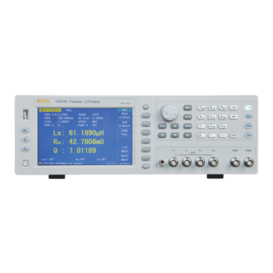
Page 9: Chapter 2 Introduction
Chapter 2 Introduction Chapter 2 Introduction In this chapter, the basic operation features of U2829 series are described. Please read the content carefully before using U2829 series instruments, thus you can learn the operation of U2829. 2.1 Introduction to front panel Figure 2-1 shows the front panel of U2829. - Page 10 U2829 Series Operation Manual Chapter 2 Introduction 8) [TRIG] When the trigger mode is set to MAN mode, press this key to trigger the instrument. 9) [RESET] Press this key, when transformer auto scanning is cancelled, other operation cannot be executed on other pages.
-
Page 11: Introduction To Rear Panel
U2829 Series Operation Manual Chapter 2 Introduction 2.2 Introduction to rear panel Figure 2-2 shows the rear panel of U2829. Figure 2-2 Rear panel 1) SCANNER interface Control the transformer scanning box through SCANNER interface. 2) IEEE-488 interface The tester can communicate with PC through GPIB interface. -
Page 12: Introduction To Display Zone
U2829 Series Operation Manual Chapter 2 Introduction 11) Power socket and Fuse base Input AC power and being used to install power fuse, protect instrument. 2.3 Introduction to display zone U2829 applies a 65k, 7-inch TFT display. The display screen is divided into the... -
Page 13: Setup]
U2829 Series Operation Manual Chapter 2 Introduction measurement display page, the following soft keys will be displayed in the soft key zone. <MEAS DISPLAY> <BIN DISPLAY> <PASS FAIL> <LIST SWEEP> <GRAPH SWEEP> When the transformer measurement function is active, press this key-[MEAS], the following soft keys will be displayed on the transformer measurement display page. -
Page 14: System]
U2829 Series Operation Manual Chapter 2 Introduction <STAT.> <SCAN MEAS> 2.4.3 [SYSTEM] This key-[SYSTEM] is used to enter into the system setup page. The following soft keys will be available: <SYSTEM SETUP> <SYSTEM INFO> <FIRMWARE UPDATE> <SYSTEM TEST> 2.5 Basic Operation... - Page 15 U2829 Series Operation Manual Chapter 2 Introduction If the password protection function is on, users are required to input the password and then press [ENTER] to enter into the page of main menu. ——————————————————————————————————————— Note: The instrument has a default password-123456. In your practical use, you can change it and set your own one.
-
Page 16: Chapter 3 Introduction To [Disp]
U2829 Series Operation Manual Chapter 3 Introduction to [DISP] Chapter 3 Introduction to [DISP] 3.1 <MEAS DISPLAY> When the LCR function is applied, press [MEAS], the <MEAS DISPLAY> page will be displayed on screen as shown in the following figure. -
Page 17: Test Function
U2829 Series Operation Manual Chapter 3 Introduction to [DISP] 3.1.1 Test function In a measurement period, U2829 can test four parameters for an impedance component: two primary parameters and two secondary parameters. Parameters that can be tested are as follows:... -
Page 18: Test Range
U2829 Series Operation Manual Chapter 3 Introduction to [DISP] Cs-Q Cs-Rs RETURN Press the soft key corresponding to your desired parameter. Then press RETURN to return to upper soft key menu. 4) Press Lp—…→, the following parameters will be shown for your choice. -
Page 19: Test Frequency
U2829 Series Operation Manual Chapter 3 Introduction to [DISP] U2829 has 8 AC measurement ranges: 10Ω, 100Ω, 300Ω, 1kΩ, 3kΩ, 10kΩ, 30kΩ, 100kΩ. U2829 has 10 DCR measurement ranges: 100mΩ, 1Ω, 10Ω, 100Ω, 300Ω, 1kΩ, 3kΩ, 10kΩ, 30kΩ, 100kΩ. Operation steps for setting test range: 1) Move the cursor to the range zone, the following soft keys will be displayed: AUTO The soft key is used to set the range mode to AUTO. -
Page 20: Test Level
U2829 Series Operation Manual Chapter 3 Introduction to [DISP] selectable frequencies are the same as that of ↑(+). ↓(--) This is a coarse adjustment soft key used to decrease the frequency. The selectable frequencies are the same as that of ↑(++). -
Page 21: Dc Bias
U2829 Series Operation Manual Chapter 3 Introduction to [DISP] 3.1.5 DC bias U2829 provides internal DC bias voltage from -10V to +10V. When the test function is selected as DCR, the bias zone will display “---”. Operation steps for setting DC bias: U2829 provides two methods to set the DC bias. -
Page 22: Tools
U2829 Series Operation Manual Chapter 3 Introduction to [DISP] 3.1.7 Tools The test result of U2829 is displayed as 6 floating-point digits. Decimal point lock function can make U2829 output the test result in fixed way. Meanwhile this function can change the displayed count of test result. This displayed result can be selected to be shown in large character or small character. -
Page 23: Comparator Function
U2829 Series Operation Manual Chapter 3 Introduction to [DISP] U2829303 The following control parameters can be set on <BIN DISPLAY>. Compare function ON/OFF (BIN CMP) Counter switch ON/OFF(COUNTER) There are 2 zones: BIN NO. DISP, COMP. Their detailed information will be introduced as below. -
Page 24: Func
U2829 Series Operation Manual Chapter 3 Introduction to [DISP] 2) Select one of above soft keys to set the compare function as ON or OFF. 3.2.2 FUNC Parameter zone shows the “Function” parameter, if user selects primary and secondary parameter swap compare mode, the parameter will be displayed as swap parameter, such as: “Cp-D”... -
Page 25: List Sweep Disp
U2829 Series Operation Manual Chapter 3 Introduction to [DISP] 2) Press the soft key ON to turn on the count function. 3) Press the soft key OFF to turn off the count function. 4) On < BIN DISPLAY> page, move the cursor to TOOL zone, the following soft keys will be displayed. -
Page 26: Sweep Mode
U2829 Series Operation Manual Chapter 3 Introduction to [DISP] Fail mode(FAIL MODE) There are 2 zones on this page: LIST SWEEP DISP and mode. List sweep points cannot be set on this page but can be set on <LIST SWEEP SETUP>. -
Page 27: Comp (Compare)
U2829 Series Operation Manual Chapter 3 Introduction to [DISP] below this item are the sweep results. 3.3.4 COMP (Compare) This zone indicates the compare results of the currently swept points. L means the result is lower than the standard and H is higher than the standard, while blank is medium. -
Page 28: Trigger Mode
U2829 Series Operation Manual Chapter 3 Introduction to [DISP] Output Resistance (SOUR IMP) Average times (AVG) Voltage Level Monitor ON/ OFF (VAC MON) Current Level Monitor ON/ OFF (IAC MON) Bias Current Isolation ON/ OFF (DCI ISO) ... -
Page 29: Auto Level Control Function
U2829 Series Operation Manual Chapter 3 Introduction to [DISP] 1) Move the cursor to the TRIG zone, the following soft keys will be displayed: 2) Use above soft keys to set the trigger mode. 3.4.2 Auto level control function Auto level control function can adjust the real test level (voltage across or current through DUT) to the test level value. -
Page 30: Average
U2829 Series Operation Manual Chapter 3 Introduction to [DISP] ——————————————————————————————————————— Note: Bias current isolation function (ISO) can only be set as ON after installing bias board. After bias current isolation function is turned on, the test accuracy will be influenced, so under the condition of low frequency and bias current, the bias current isolation function should be set as OFF. -
Page 31: Delay Time
U2829 Series Operation Manual Chapter 3 Introduction to [DISP] OFF. 1) Move the cursor to VAC MON zone, the following soft keys will be displayed. 2) Press ON to set the voltage monitor function as ON while press OFF to set the voltage monitor function as OFF. -
Page 32: Deviation Test Function
U2829 Series Operation Manual Chapter 3 Introduction to [DISP] 2) Press 100Ω to select the output impedance as 100Ω. Press 25Ω to select the output impedance as 25Ω. 3.4.8 Deviation test function The deviation test function can make the deviation value (instead of real test value) be directly displayed on the screen. -
Page 33: Correction
U2829 Series Operation Manual Chapter 3 Introduction to [DISP] ΔABS Δ% 6) Use above soft keys to se the deviation mode of the primary parameter. 7) Move the cursor to the DEV B zone, the following soft keys will be displayed. -
Page 34: Open
U2829 Series Operation Manual Chapter 3 Introduction to [DISP] Frequency points of OPEN, SHOR and LOAD (SPOT NO.,FREQ) Reference values for 3 frequency points of load correction ( REF A, REF B) There are 16 zones on this page: Correction, Open, Short, Load, Cable, CH Mode, Func, SPOT NO., FREQ, REF A, REF B, OPEN A, OPEN B, SHORT A,... -
Page 35: Short
U2829 Series Operation Manual Chapter 3 Introduction to [DISP] 800 Hz 8 kHz 80 kH 64 open correction frequencies can be set in SOPT NO. and FREQ on <CORRECTION>: Move the cursor to SPOT NO. and then use the INCR++,INCR+,DECR-,DECR-- soft key to set the 64 points frequencies respectively. -
Page 36: Load
U2829 Series Operation Manual Chapter 3 Introduction to [DISP] No matter what the current frequency is, U2829 will execute short correction test on the 41 fixed frequency points. Except the 41 frequencies, the instrument will adopt imbedding algorithm to calculate the short correction data of different test frequencies which correspond to different ranges. - Page 37 U2829 Series Operation Manual Chapter 3 Introduction to [DISP] in the setup zones of REF A and REF B. The standard test function must be set in the Func zone before setting standard reference value. When the cursor moves to FREQ, the MEAS LOAD soft key will be displayed. Press MEAS LOAD to perform the load correction test.
-
Page 38: Load Correction Test Function
U2829 Series Operation Manual Chapter 3 Introduction to [DISP] 7) Make the test fixture be open. 8) Press SPOT OPEN to perform open correction at the current set frequency. The test result (G, B) of the open correction test will be displayed in the help line (the bottom line). -
Page 39: Cable Length Selection
U2829 Series Operation Manual Chapter 3 Introduction to [DISP] 3.5.5 Cable length selection The available cable length is 0m, 1m, 2m and 4m. 3.5.6 Single/ multi correction mode Refer to the instruction of the scanting optional interface. <LIMIT TABLE> Press [SETUP] and then LIMIT TABLE to enter into the <LIMIT TABLE SETUP>... -
Page 40: Swap Parameter
U2829 Series Operation Manual Chapter 3 Introduction to [DISP] Compare function ON/OFF (BIN COM) Low limit of each bin (LOW) High limit of each bin (HIGH) 3.6.1 Swap parameter The swap parameter function can swap the primary and the secondary parameter in FUNC. -
Page 41: Set Nominal Value Of Tolerance Mode
U2829 Series Operation Manual Chapter 3 Introduction to [DISP] Figure 3-3 Tolerance mode and Sequential mode ——————————————————————————————————————— Note: When setting limit values of tolerance mode, the error range should be set in the order from small to large. If the error range of BIN1 is the largest one, then all DUT will sort into BIN 1. -
Page 42: Comparator Function On/Off
U2829 Series Operation Manual Chapter 3 Introduction to [DISP] the display range. When the sequential mode is selected as the limit mode the primary parameter, the nominal value can be set, but it is not necessary to use it under this mode. -
Page 43: High/Low
U2829 Series Operation Manual Chapter 3 Introduction to [DISP] out of the limit range, the DUT will be sorted into the AUX BIN. ——————————————————————————————————————— Note: When the secondary parameter only has low limit and the auxiliary bin is set as ON, if the primary parameter of DUT is within the limit range and the secondary parameter is smaller than or equal to its low limit, the DUT will be sorted into the auxiliary bin. -
Page 44: List Setup
U2829 Series Operation Manual Chapter 3 Introduction to [DISP] the data, you can use (p, n, µ, m, k, M, *1) to replace [ENTER] to input the limit value. When [ENTER] is used to input the limit value, the default unit is the same as that being input last time. -
Page 45: Mode
U2829 Series Operation Manual Chapter 3 Introduction to [DISP] Sweep test point setup (sweep point) Selection of limit parameter (LMT) High/low limit (HIGH, LOW) 3.7.1 MODE Mode menu is the same as the mode on <List sweep display> page. -
Page 46: Chapter 4 [System] And
U2829 Series Operation Manual Chapter 4 [SYSTEM] and [FILE] Chapter 4 [SYSTEM] and <FILE MANAGE> 4.1 <SYSTEM SETUP> Press [System] and then SYSTEM SETUP to enter into the <SYSTEM SETUP> page shown as below. U2829401 On this page, most system setup items are displayed, such as instrument main function, beeper, PASS beeper, FAIL beeper, language, PASS word, bus mode, GPIB address, TALK only, Bias SRC, baud rate, data/time. -
Page 47: On Beepers
U2829 Series Operation Manual Chapter 4 [SYSTEM] and [FILE] 4.1.2 ON BEEPERS This zone is used to control and display the beeper source. Operation steps for selecting beeper 1) Move the cursor to Beeper, the following soft keys will be displayed. -
Page 48: Language
U2829 Series Operation Manual Chapter 4 [SYSTEM] and [FILE] HIGH LONG This soft key is used to select high and long beep. LOW LONG This soft key is used to select low and short beep. SHORT This soft key is used to select high and short beep. -
Page 49: Bus Mode (Reserved Function)
U2829 Series Operation Manual Chapter 4 [SYSTEM] and [FILE] follows: Press MODIFY to input a new password. After inputting, a prompt information will appear on the screen to prompt you to confirm the new password. Input the new password again till the modification finishes. -
Page 50: Bias Src
U2829 Series Operation Manual Chapter 4 [SYSTEM] and [FILE] AUTO 2) Press QUERY to turn on the talk only function or AUTO to turn off this function. 4.1.10 BIAS SRC Bias source is used to select the DC bias power. The instrument provides 3 kinds... -
Page 51: Data/Time
U2829 Series Operation Manual Chapter 4 [SYSTEM] and [FILE] 1) Move the cursor to BAUD RATE, the following soft keys will be displayed. 4800 9600 19200 38400 57600 115200 2) Use above soft key is to set the baud rate. -
Page 52: System Test
U2829 Series Operation Manual Chapter 4 [SYSTEM] and [FILE] 2) Press UPDTE, the following soft keys will be displayed. 3) Press YES soft key to update the firmware of the instrument. 4.1.15 SYSTEM TEST Press SYSTEM TEST enter into the <SYSTEM TEST> page shown as below. -
Page 53: Lcr
Chapter 4 [SYSTEM] and [FILE] 4.2 LCR <FILE MANAGE> U2829 series instrument can save the user-set parameter to the nonvolatile memory in the form of file, so when use the same setting next time user can load a corresponding file to obtain the parameter set and used last time. By doing so, it can save the time of setting parameter and improve the production efficiency. - Page 54 U2829 Series Operation Manual Chapter 4 [SYSTEM] and [FILE] DC BIAS BIAS SRC TRIGG DELAY Rsou DEV A DEV B REF A REF B Control and set parameters on <BIN COUNT DISP> page ...
-
Page 55: U-Disk Manage Performance
U2829 Series Operation Manual Chapter 4 [SYSTEM] and [FILE] 4.2.2 U-disk manage performance As described above, U2829 has a standard configuration of USB HOST interface, so the external U-disk can be used as the memory media. In this condition, it breaks the memory limit of 100 groups of *.LCR files. - Page 56 U2829 Series Operation Manual Chapter 4 [SYSTEM] and [FILE] SAVE DELETE COPY SEARCH 2) In the file list, move the cursor to the file-saved position or input the file number directly. 3) Press LOAD, the following soft keys will be displayed.
-
Page 57: Chapter 5 Execute Lcr Operation And Some Examples
U2829 Series Operation Manual Chapter 5 Execute LCR Operation and Some Examples Chapter 5 Execute LCR operation and some examples 5.1 Correction operation To execute correction operation (in order to prevent the stray impedance from affecting the test accuracy, it is necessary to make open/short correction), users can select one of the two correction modes. -
Page 58: Correct Connection Of Dut
U2829 Series Operation Manual Chapter 5 Execute LCR Operation and Some Examples displayed in the soft key zone. c) Press ON to turn on the open correction function. d) Move the cursor to the Short zone, ON, OFF and SWEEP SHORT will be displayed in the soft key zone. -
Page 59: Eliminate The Influence Of Stray Impedance
U2829 Series Operation Manual Chapter 5 Execute LCR Operation and Some Examples change stray capacitance and inductance on test terminals and this problem is unavoidable, because the test leads cannot be fixed in a position. So, the use of the test fixture should be used as possible in high frequency. If the test fixture is unavailable or cannot be used, the status of test leads should be the same in the processes of correction and test. - Page 60 U2829 Series Operation Manual Chapter 5 Execute LCR Operation and Some Examples Shielding ground Test terminal Metal conductor Figure 5-1 Influence of stray capacitance Shielding ground Shielding plate Test terminal Metal conductor Figure 5-2 Eliminate the influence of stray capacitance When the DUT has high impedance(such as small capacitance), the influence of stray capacitance cannot be ignored.
-
Page 61: Operation Example For Testing Inductance With U2829
U2829 Series Operation Manual Chapter 5 Execute LCR Operation and Some Examples coupling on test results. 5.4 Operation example for testing inductance with U2829 Test Condition Function: Ls-Q Frequency: 5.5kHz Level: 1.5Vrms Internal impedance: 100Ω Operation steps 1) Turn on the instrument. -
Page 62: Operation Example Of Testing Capacitance By Multi-Frequency List Sweep
U2829 Series Operation Manual Chapter 5 Execute LCR Operation and Some Examples U2829501 7) If the test result is obviously incorrect, please check the following items. a) Check the tested inductance is in good connection with the test fixture or not. - Page 63 U2829 Series Operation Manual Chapter 5 Execute LCR Operation and Some Examples a) Press [MEAS] to enter into the <MEAS DISPLAY> page. b) The FUNC A-B zone is currently displayed as Cp-D and the Level zone is 1.000V. c) Press [SETUP] to enter into the <MEAS SETUP> page, meanwhile the following soft keys will be displayed in the soft key zone: MEAS SETUP, CORRECTION, LIMIT TABLE, LIST SETUP and GRAPH SETUP.
- Page 64 U2829 Series Operation Manual Chapter 5 Execute LCR Operation and Some Examples zone and the soft key zone will display the following available units: p, n, μ, m. Press ENTER, this zone will be changed as 0.00200. v) Based on l-u steps, input 100kHz, 0.0060 and 0.0100 for the 3rd sweep point.
-
Page 65: Operation Example Of Load Correction
U2829 Series Operation Manual Chapter 5 Execute LCR Operation and Some Examples 5.6 Operation example of load correction 1) Operation steps Test condition Frequency: 100kHz Cp: 11nF D: 0.0005 a) Press [SETUP], the following soft keys will be displayed in the soft key zone: MEAS SETUP, CORRECTION, LIMIT TABLE LIST SETUPand GRAPH SETUP. - Page 66 U2829 Series Operation Manual Chapter 5 Execute LCR Operation and Some Examples Insert the short plate (U26010) into the test fixture. Please ensure that the short plate and the reeds of the test fixture have good contact. s) Press the soft key SPOT SHORT to execute short correction.
-
Page 67: Chapter 6 Performance And Test
U2829 Series Operation Manual Chapter 6 Performance and Test Chapter 6 Performance and Test 6.1 Test function 6.1.1 Parameter and symbol C:capacitance L:Inductance R:resistance Z:impedance Y:Admittance X:reactance B:susceptance G:Conductance D:dissipation :phase angle Q:Quality factor Lk: leakage inductance DCR: DC resistance... -
Page 68: Delay Time
U2829 Series Operation Manual Chapter 6 Performance and Test Internal: Test DUT constantly and display the result Manual: Press TRIGGER to test once then the result will be displayed. External: After HANDLER receiving “start” signal, perform a measurement and output test result. -
Page 69: Signal Mode
U2829 Series Operation Manual Chapter 6 Performance and Test 20Hz~1MHz (U2829B) Min. resolution:0.5mHz 6.2.2 Signal mode Normal: When testing, on measurement display page, voltage across test terminals may be smaller than preset voltage. Constant level: The auto adjustment of internal level makes the voltage of DUT accordant with preset voltage. -
Page 70: Dc Bias Voltage Source
U2829 Series Operation Manual Chapter 6 Performance and Test Y、B、G 0.00001μs ~ 99.9999S 0.00001 — 9.99999 0.00001 — 99999.9 -179.999°~179.999° θ -3.14159 ~ 3.14159 1:0.001—1000:1 Turns Ratio 6.2.7 DC bias voltage source 0V— ± 10V Minimum resolution: 0.5mV, Accuracy: 1%xpreset voltage+5mV 0mA—±... -
Page 71: Accuracy Of D
U2829 Series Operation Manual Chapter 6 Performance and Test WhenD ≥0.1, L, C, X, B accuracy factor A should be multiplied by When Q ≥0.1, R, G accuracy factor A should be multiplied by Accuracy of G can only be available in G-B combination 6.3.2 Accuracy of D... -
Page 72: Accuracy Of Rp
U2829 Series Operation Manual Chapter 6 Performance and Test is the accuracy of D. F is test frequency. The accuracy of G is only available in C -G and L -G combination 6.3.6 Accuracy of Rp when D (value of tested D)≤0.1 The accuracy of R is given by the formula below:... - Page 73 U2829 Series Operation Manual Chapter 6 Performance and Test 100kH 10kH [OHM] 10pF 100fF 10pF 100H 100pF 100M 100n 1.5M 10nF 100mH 100nF 100k 10mH 100u 0.05 10uF 100uH 100uF 10uH 100m 10mF 0.25 0.35 100nH 100mF 100m 0.65 10nH...
- Page 74 U2829 Series Operation Manual Chapter 6 Performance and Test Figure B is the basic accuracy modification curve, where V is the test signal voltage. 100m 150m [Vrms] 200m 500m Table A Impedance rate factors: K Speed Frequency ...
-
Page 75: Accuracy Of Dcr
U2829 Series Operation Manual Chapter 6 Performance and Test Direct calibrated frequency Other frequency 0.0003 Table C Direct Calibrated frequency [Hz] [Hz] [kHz] [kHz] [kHz] There are 43 frequencies in table C, there is no 250kHz and 300kHz in U2829. -
Page 76: Safety Requirement
U2829 Series Operation Manual Chapter 6 Performance and Test 6.4 Safety requirement The instrument is the Ⅰ class safety instrument. 6.4.1 Insulation resistance Under reference working condition,the insulation resistance between power terminal and instrument jacket should not be smaller than50MΩ. -
Page 77: Function Check
U2829 Series Operation Manual Chapter 6 Performance and Test capacitor 1000pF D is known 10000pF 10nF 0.1uF 10Ω 100Ω 0.02% 1kΩ standard resistor 10kΩ 100kΩ 0.1Ω 1Ω 10Ω 0.02% 100Ω standard resistor 1kΩ 10kΩ 100kΩ 100μH Standard inductor 0.02% 10mH... -
Page 78: Measurement Accuracy
U2829 Series Operation Manual Chapter 6 Performance and Test 10kHz, 100kHz, 200kHz(U2829 is 200kHz). The reading of frequency meter should meet the demand of the test signal frequency in this chapter. 6.6.6 Measurement accuracy Basic parameters are R, L, C and D,so measurement accuracy is mainly about R, L, C and D. -
Page 79: Accuracy Of Dcr
U2829 Series Operation Manual Chapter 6 Performance and Test Open and short correction should be made before testing. Connect standard AC resistors: 10Ω, 100Ω, 1kΩ, 10kΩ, 100kΩ and change the frequency. The error between reading and nominal value should be in the range ruled in this chapter. -
Page 80: Chapter 7 Command Reference
U2829 Series Operation Manual Chapter 7 Command Reference Chapter 7 Command Reference The signs in this manual are as follows: NR1: integer, e.g.:123 NR2: fix-point number, e.g.: 12.3 NR3: floating-point number, e.g.: 12.3E+5 NL: carriage key, ASCII code: 10 ˆEND: EOI signal in IEEE-488 7.1 Subsystem commands for U2829... - Page 81 U2829 Series Operation Manual Chapter 7 Command Reference DISPlay :PAGE MEASurement BNUMber BCOunt LIST MSETup CSETup LTABle LSETup SYSTem FLISt TTSe t TLSet TMDisp TJDisp TSDisp :LINE “<string>” :RFONt LARGe TINY The :PAGE command sets the display page. The :DISPlay:PAGE? query returns the current page.
- Page 82 U2829 Series Operation Manual Chapter 7 Command Reference measurement display page. Query syntax: DISPlay:PAGE? Return format: <page name><NL^END> <page name> can be set as the following items: <LCR MEAS DISP> The current page is the LCR measurement display page. <BIN No. DISP>...
-
Page 83: Frequency Subsystem Commands
U2829 Series Operation Manual Chapter 7 Command Reference LARGE TINY 7.1.2 FREQuency subsystem commands The FREQuency subsystem commands are mainly used to set the measurement frequency of the instrument. The :FREQuency query returns the current measurement frequency. <value> Command syntax:... -
Page 84: Amplitude Subsystem Commands
U2829 Series Operation Manual Chapter 7 Command Reference current. The CURRent? query returns the current measurement current. Command syntax: <value> CURRent Where, <value> NR1, NR2 or NR3 data format followed by MA. Set the measurement current as 50μA. Set the measurement current as 20mA. -
Page 85: Output Subsystem Commands
U2829 Series Operation Manual Chapter 7 Command Reference Query syntax: ORESister? Return format: <NR1><NL^END> 7.1.7 OUTPut subsystem commands The OUTPut subsystem commands are mainly used to set the status of the 1A DC bias source and DC isolation function. Command tree:... -
Page 86: Bias Subsystem Commands
U2829 Series Operation Manual Chapter 7 Command Reference OUTPut:DC:ISOLation Where, Character 1 (49) is equal to ON. Character 0 (48) is equal to OFF. Query syntax: OUTPut:DC:ISOLation? Return format: <NR1><NL^END> 7.1.8 BIAS subsystem commands The :BIAS subsystem commands are mainly used to set the internal bias voltage and the bias status. -
Page 87: Function Subsystem Commands
U2829 Series Operation Manual Chapter 7 Command Reference BIAS:VOLTage? query returns the current bias voltage. Command syntax: <value> BIAS:VOLTage Where, <value> NR1, NR2 or NR3 data format. Set the bias voltage as 0V. Set the bias voltage as 10V. For example: WrtCmd (“BIAS:VOLT MIN”) Set the DC bias voltage as 0V. - Page 88 U2829 Series Operation Manual Chapter 7 Command Reference FUNCtion :IMPedance CPRP CSRS LPRP LSRS :RANGe <value> :AUTO ON (1) OFF (0) :Source MONitor :VAC ON (1) OFF (0) :IAC ON (1) OFF (0) :DEV1 :MODE ABSolute PERcent :REFerence <value> :FILL The FUNCtion:IMPedance command is used to set instrument functions.
- Page 89 U2829 Series Operation Manual Chapter 7 Command Reference CPRP Set the function as Cp-Rp LSRS Set the function as Ls-Rs Set the function as Cs-D Set the function as R-X ◦ Set the function as Cs-Q Set the function as Z-θ...
- Page 90 U2829 Series Operation Manual Chapter 7 Command Reference ON (1) FUNCtion:SMONitor:VAC OFF (0) Where, Character 1 (49) is equal to ON. Character 0 (48) is equal to OFF. For example: WrtCmd (“FUNC:SMON:VAC ON”) Set the voltage monitor as ON. Query syntax: FUNCtion:SMONitor:VAC? Return format: <NR1><NL^END>...
-
Page 91: List Subsystem Commands
U2829 Series Operation Manual Chapter 7 Command Reference PERC <NL^END> The FUNCtion:DEV<n>:REFerence<value> command is used to set the nominal value of the deviation. The FUNCtion:DEV<n>:REFernece<value>? query returns the current nominal value of the deviation. Command syntax: FUNCtion:DEV<n>:REFerence<value> Where, <value> is NR1, NR2 or NR3 data format. - Page 92 U2829 Series Operation Manual Chapter 7 Command Reference The LIST:FREQuency command is used to clear the original sweep points and set the frequencies of the sweep points. The LIST:FREQuency? query returns the current frequency of each sweep point. Command syntax: LIST:FREQuency<value>[,<value>*] NOTE: * part means 10 sweep points at most can be set.
- Page 93 40mA. Query syntax: LIST:BIAS:CURRent? Return format: <NR3>[,<NR3>*]<NL^END> NOTE: U2829 series instrument has installed a 10V/100mA internal DC bias current source. If 1A DC source is required, please install an external source. U2829 can be used with TH1773 DC Bias Source...
-
Page 94: Aperture Subsystem Commands
U2829 Series Operation Manual Chapter 7 Command Reference company). The LIST:MODE command is used to set the list sweep mode. The LIST:MODE? query returns the current list sweep mode. Command syntax: SEQuence LIST:MODE STEPped Where, SEQuence means sequential mode. STEPped means single step mode. -
Page 95: Trigger Subsystem Commands
U2829 Series Operation Manual Chapter 7 Command Reference FAST APERture MEDium [,<value>] SLOW Where, FAST: 30 times/sec MEDium: 10 times/sec SLOW: 2 times/sec <value> 1 to 255 in NR1 For example: WrtCmd (“APER MED, 55”) Query syntax: APERture? Return format: FAST , <NR1><NL^END>... -
Page 96: Fetch? Subsystem Commands
U2829 Series Operation Manual Chapter 7 Command Reference EXTernal Triggered by HANDLER interface. Triggered by RS232C interface or GPIB interface HOLD Triggered by pressing TRIGGER. For example: WrtCmd (“TRIG:SOUR BUS”) Query syntax: TRIGger:SOURce? Return format: <NL^END> HOLD The TRIGger:DELay command is used to set the delay time after triggering. The TRIGger:DELay? query returns the current delay time. - Page 97 U2829 Series Operation Manual Chapter 7 Command Reference WrtCmd (“FETC?”) U2829 applies ASCII to delivery result, details are follows. On measurement display page, bin NO. display page, bin count display page, ASCII data output format are described as below: SN.NNNNNESNN , SN.NNNNNESNN , SN , SN or SNN NL^END <DATA A>...
- Page 98 U2829 Series Operation Manual Chapter 7 Command Reference Only when the instrument compare function is set as ON, <bin No.> data can be displayed. The output format of <bin No.> data applies 2 to 3 digits ASCII: SN or SNN (S: +/_, N: from 0 to 9).
-
Page 99: Correction Subsystem Commands
U2829 Series Operation Manual Chapter 7 Command Reference When the measurement parameter is inductance (Zx), secondary parameter <DATA B> is the phase angle θ, its description is the same as that of <DATA A>. When the measurement parameter is inductance (Acr), secondary parameter of <DATA B>... - Page 100 U2829 Series Operation Manual Chapter 7 Command Reference CORRection :LENGth <value> :METHod SINGle MULTiple :OPEN :STATe ON (1) OFF (0) :SHORt :STATe ON (1) OFF (0) :LOAD :STATe ON (1) OFF (0) :TYPE CPRP CSRS LPRP LSRS :SPOT1 :STATe ON (1) OFF (0) :FREQuency <value>...
- Page 101 U2829 Series Operation Manual Chapter 7 Command Reference Query syntax: CORRection:LENGth? Return format: <NR1><NL^END> The CORReciton:METHod command is used to set the correction mode. The CORRection:METHod? query returns the current correction mode. Command syntax: CORRection:METHod SINGle MULTi Where, SINGle Set or return single channel mode.
- Page 102 U2829 Series Operation Manual Chapter 7 Command Reference The CORRection:SHORt:STATe? query returns the current short correction status. Command syntax: CORRection:SHORt:STATe Where, 1 (decimal 49) is equal to ON. 0 (decimal 48) is equal to OFF. For example: WrtCmd (“CORR:SHOR:STAT ON”) Query syntax: CORRection:SHORt:STATe? Return format: <NR1><NL^END>...
- Page 103 U2829 Series Operation Manual Chapter 7 Command Reference Query syntax: CORRection:LOAD:TYPE? Return format: <function><NL^END> The CORRection:SPOT<n>:STATe command is used to set the state of some specific frequency spots. The CORRection:SPOT<n>:STATe query returns the current state of each frequency spot (FREQ 1, FREQ 2 or FREQ 3).
- Page 104 U2829 Series Operation Manual Chapter 7 Command Reference Command syntax: CORRection:SPOT<n>:OPEN Where, <n>: 1 refers to frequency spot 1. 2 refers to frequency spot 2. 3 refers to frequency spot 3. For example: WrtCmd (“CORR:SPOT1:OPEN”) Execute open correction for frequency spot 1.
-
Page 105: Comparator Subsystem Commands
U2829 Series Operation Manual Chapter 7 Command Reference Where, <channel number> ranges from 1 to 127 (NR1, NR2 or NR3 data format). For example: WrtCmd (“CORR:USE 10”) Set the channel number as 10. Query syntax: CORRection:USE? Return format: <channel number><NL^END>... - Page 106 U2829 Series Operation Manual Chapter 7 Command Reference COMParator [:STATe] ON (1) OFF (0) :MODE Absolute TOLerance Percent TOLerance SEQuence :TOLerance :NOMinal <value> :BIN<n> <low limit>,<high limit> :SEQuence :BIN <BIN1 low limit>,<BIN1 high limit>, <BIN2 high limit>,<BIN3 high limit>, …… ,<BINn high limit>...
- Page 107 U2829 Series Operation Manual Chapter 7 Command Reference ATOLerance means absolute tolerance mode. PTOLerance means proportional tolerance mode. SEQuence means sequential tolerance mode. For example: WrtCmd (“COM:MODE ATOL”) Query syntax: COMParator:MODE? Return format: ATOL PTOL <NL^END> The COMParator:TOLerance:NOMinal command is used to set the nominal value (this function is valid only when the limit mode is set as deviation mode).
- Page 108 U2829 Series Operation Manual Chapter 7 Command Reference Where, <BIN1 low limit> is the low limit of BIN 1 in NR1, NR2 or NR3 data format. <BIN1 high limit> is the high limit of BIN1 in NR1, NR2 or NR3 data format.
- Page 109 U2829 Series Operation Manual Chapter 7 Command Reference ON, the function parameter will be changed as D-Cp. In this case, the limits from BIN1 to BIN9 become the high and the low limits of D, the original secondary limits become that of Cp. That is to say, this function is to make swap comparison between the primary and the secondary parameters.
-
Page 110: Mass Memory Subsystem Commands
U2829 Series Operation Manual Chapter 7 Command Reference count>, <AUX BIN count><NL^END> Where, <BIN1-9 count> is the count result of BIN1-9, in NR1 data format. <OUT OF BIN count> is the count result of the OUT OF BIN, in NR1 data format. - Page 111 U2829 Series Operation Manual Chapter 7 Command Reference TRAN :TURN :STAT ON (1) OFF(0) :FREQ <value> :LEVel <value> :Np LIMit <value>,<low limit>,<high limit> :Ns LIMit <value>,<low limit>,<high limit> :STAT ON (1) OFF(0) :FREQ <value> :LEVel <value> :LIMit <value>,<low limit>,<high limit>...
- Page 112 U2829 Series Operation Manual Chapter 7 Command Reference TRAN:TURN:STAT Where, 1 (decimal 49) is equal to ON. 0 (decimal 48) is equal to OFF. For example: WrtCmd (“TRAN:TURN:STAT:ON”) All test parameter setting of turn-ratio is valid. Query syntax: TRAN:TURN:STAT? Return format: <NR1><NL^END>...
- Page 113 U2829 Series Operation Manual Chapter 7 Command Reference NOTE: The low limit should be smaller than the high limit, or error information will be reported. For example: WrtCmd (“TRAN:TURN:NPLI 100, -0.01, 0.01”) Query syntax: TRAN:TURN:NPLI? Return format: <NR3>, <NR3>, <NR3><NL^END>...
- Page 114 U2829 Series Operation Manual Chapter 7 Command Reference <value> is NR1, NR2 or NR3 data format followed by HZ, KHZ and MHZ. For example: WrtCmd (“TRAN:Lk:FREQ 1KHZ”) Set the test frequency of the leakage inductance is 1KHZ. Query syntax: TRAN:Lk:FREQ? Return format: <NR3><NL^END>...
- Page 115 U2829 Series Operation Manual Chapter 7 Command Reference 0 (decimal 48) is equal to OFF. For example: WrtCmd (“TRAN:Lx:STAT:ON”) Set all Lx parameters to be valid. Query syntax: TRAN:Lx:STAT? Return format: <NR1><NL^END> The TRAN:Lx:FREQ command is used to set the Lx test frequency. The TRAN:Lx;FREQ query returns the current Lx test frequency.
- Page 116 U2829 Series Operation Manual Chapter 7 Command Reference The TRAN:Zx:STAT command is used to set the Zx test parameter as ON or OFF. The TRAN:Zx:STAT? query returns the current state of the Zx test parameter. Command syntax: TRAN:Zx:STAT Where, 1 (decimal 49) is equal to ON.
- Page 117 U2829 Series Operation Manual Chapter 7 Command Reference Command syntax: TRAN:ACR:STAT Where, 1 (decimal 49) is equal to ON. 0 (decimal 48) is equal to OFF. For example: WrtCmd (“TRAN:ACR:STAT:ON”) Set the ACR test parameter to be valid. The TRAN:ACR:FREQ command is used to set the ACR test frequency. The TRAN:ACR:FREQ? query returns the current ACR test frequency.
- Page 118 U2829 Series Operation Manual Chapter 7 Command Reference The TRAN:Cx:STAT command is used to set the Cx test parameter to be ON or OFF. The TRAN:Cx:STAT query returns the current state of the Cx test parameter. Command syntax: TRAN:Cx:STAT Where, 1 (decimal 49) is equal to ON.
- Page 119 U2829 Series Operation Manual Chapter 7 Command Reference <value> is the Cx nominal value in NR1, NR2 or NR3 data format followed by H. <low limit> is the low limit in NR1, NR2 or NR3 data format. <high limit> is the high limit in NR1, NR2 or NR3 data format.
-
Page 120: Gpib Common Commands
U2829 Series Operation Manual Chapter 7 Command Reference TRAN:MODE SEQuence STEPped Where, SEQuence refers to sequential mode. STEPped refers to single step mode. For example: WrtCmd (“TRAN:MODE SEQ”) Query syntax: TRAN:MODE? Return format: <NL^END> STEP 7.2 GPIB Common Commands ●*RST ●*TRG... - Page 121 U2829 Series Operation Manual Chapter 7 Command Reference Command syntax: *ESE<value> Where, <value> NR1 format:decimal expression for each bit of operation status register. Descriptions for each byte of the standard event status register are shown as follows: Bit number Description...
- Page 122 U2829 Series Operation Manual Chapter 7 Command Reference Bit number Description Power On(PON) Bit User Request(URQ) Bit Command Error(EME) Bit Execution Error(EXE) Bit Device Dependent Error(DDE) Bit Query Error(QYE) Bit Request Control(RQC) Bit Operation Complete(OPC) Bit For example: WrtCmd (“*ESR?”) The *STB? query returns contents of the standard service status byte register.
Need help?
Do you have a question about the U2829 Series and is the answer not in the manual?
Questions and answers