Table of Contents
Advertisement
Quick Links
O
P
E
R
O
P
E
R
U2836 Precision LCR meter
C C
h h
a a
n n
g g
z z
h h
o o
u u
C
h
a
n
g
z
h
o
A A
d d
d d
: : No.1, Ziyang Road, Tianning District, Changzhou, Jiangsu
A
d
d
:
T T
e e
l l
T
e
F F
a a
x x
F
a
E E
- -
m m
E
-
W W
e e
b b
W
e
b
A
T
I
O
N
A
T
I
O
N
E E
u u
c c
o o
l l
E E
l l
e e
c c
u
E
u
c
o
l
E
l
e
c
: :
0 0
5 5
1 1
9 9
8 8
5 5
5 5
0 0
5 5
1 1
9 9
( (
) )
l
:
0
5
1
9
8
5
5
0
5
1
(
)
: :
0 0
5 5
1 1
9 9
8 8
5 5
5 5
0 0
5 5
1 1
( (
) )
x
:
0
5
1
9
8
5
5
0
5
1
(
)
a a
i i
l l
: :
S S
a a
l l
e e
s s
@ @
e e
u u
c c
o o
l l
m
a
i
l
:
S
a
l
e
s
@
e
u
c
o
l
s s
i i
t t
e e
: :
h h
t t
t t
p p
: :
/ /
/ /
w w
w w
w w
. .
s
i
t
e
:
h
t
t
p
:
/
/
w
w
w
I
M
A
N
U
A
M
A
N
U
A
t t
r r
o o
n n
i i
c c
C C
o o
. .
, ,
t
r
o
n
i
c
C
o
.
,
9 9
9
9
6 6
9 9
6
9
. .
c c
o o
m m
. .
c c
n n
.
c
o
m
.
c
n
e e
u u
c c
o o
l l
. .
c c
o o
m m
. .
c c
n n
.
e
u
c
o
l
.
c
o
m
.
c
n
L
L
L L
t t
d d
. .
L
t
d
.
Advertisement
Table of Contents

Related Manuals for EUCOL U2836


Summary of Contents for EUCOL U2836
- Page 1 U2836 Precision LCR meter : : No.1, Ziyang Road, Tianning District, Changzhou, Jiangsu ( ( ) ) ( ) ( ( ) ) ( )...
-
Page 2: Table Of Contents
U2836 Operation Manual Contents Contents Chapter 1 Out of Box Audit ......................1 1.1 To Inspect the package ....................1 1.2 Power connection ......................1 1.3 Fuse ..........................1 1.4 Environment ......................... 2 1.5 Use of Test Fixture ....................... 2 ... - Page 3 Execute LCR operation and some examples .............. 38 5.1 Correct connection of DUT ..................38 5.2 Eliminate the influence of stray impedance ............... 39 5.3 Operation example for testing inductance with U2836 ..........41 Chapter 6 Performance and Test ....................43 6.1 Test function ....................... 43 6.1.1 ...
- Page 4 U2836 Operation Manual Contents 6.1.11 Display digit ....................44 6.2 Test signal ........................44 6.2.1 Test signal frequency ................. 44 6.2.2 Signal mode ....................44 6.2.3 Test signal level .................... 45 6.2.4 Output impedance ..................45 6.2.5 Monitor for test signal level ..............45 ...
-
Page 5: Out Of Box Audit
U2836 Operation Manual Chapter 1 Out of Box Audit Chapter 1 Out of Box Audit When you receive the instrument, some inspections are necessary, and the condition must be understood and available before installing the instrument. 1.1 To Inspect the package Inspect the shipping container for damage after unpacking it. -
Page 6: Environment
U2836 Operation Manual Chapter 1 Out of Box Audit 1.4 Environment 1) Please do not operate the instrument in the place that is vibrative, dusty, under direct sunlight or where there is corrosive air. 2) The normal working temperature is 0℃~40℃, relative humidity ≤75%, so the instrument should be used under above condition to guarantee the accuracy. -
Page 7: Other Features
U2836 Operation Manual Chapter 1 Out of Box Audit 1.7 Other features 1) Power: consumption power≤20VA. 2) Dimension (W*H*D): 280mm*88mm*320mm 3) Weight: About 3.5kg. -
Page 8: Chapter 2 Introduction
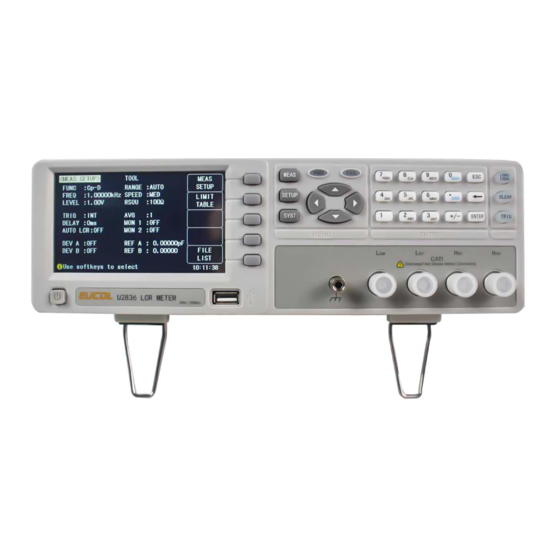
U2836 Operation Manual Chapter 2 Introduction Chapter 2 Introduction In this chapter, the basic operation features of U2836 are described. Please read the content carefully before using U2836 instruments, thus you can learn the operation of U2836. 2.1 Introduction to front panel Figure 2-1 shows the front panel of U2836. - Page 9 U2836 Operation Manual Chapter 2 Introduction 9) [TRIG] When the trigger mode is set to MAN mode, press this key to trigger the instrument. 10) [LOCK/LOCAL] Press this key, the buzzer will beep, which means the function of current panel is locked. Press it again, it will be off, which means discharging the lock status.
-
Page 10: Introduction To Rear Panel
U2836 Operation Manual Chapter 2 Introduction 2.2 Introduction to rear panel Figure 2-2 shows the rear panel of U2836. 1) HANDLER interface Handler interface is used to realize the sorting output of test results. 2) External trigger interface Handler interface is used to realize the sorting output of test results. -
Page 11: Introduction To Display Zone
U2836 Operation Manual Chapter 2 Introduction 2.3 Introduction to display zone U2836 applies a 65k, 4.3-inch TFT display. The display screen is divided into the following zones: Figure 2-3 display zones 1) Display page name Indicate the name of the currently displayed page. -
Page 12: Main Menu Keys And Corresponding Displayed
<SYSTEM TEST> <FILE LIST> 2.5 Basic Operation Basic operation of U2836 is as follows: Use menu keys ([MEAS DISP], [MEAS SETUP], [SYSTEM]) and soft keys to select the desired page. Use cursor keys ([←][→]) to move the cursor to the desired zone. When the cursor moves to a specified zone, the zone will become reverse expression. -
Page 13: Start The Instrument
U2836 Operation Manual Chapter 2 Introduction displayed in the soft key zone. You can choose a unit soft key or press [ENTER] to end data inputting. When [ENTER] is used to terminate data inputting, the unit of data will be set to a default unit, such as Hz, V or A. For example, the default unit for frequency is Hz. -
Page 14: Chapter 3 Introduction To [Meas Disp]
U2836 Operation Manual Chapter 3 Introduction to [MEAS DISP] Chapter 3 Introduction to [MEAS DISP] 3.1 <MEAS DISPLAY> Press [MEAS], the <MEAS DISPLAY> page will be displayed on screen as shown in the following figure. On this page, the test result is displayed. The measurement control parameters... -
Page 15: Test Function
U2836 Operation Manual Chapter 3 Introduction to [MEAS DISP] 3.1.1 Test function In a measurement period, U2836 can test two parameters for an impedance component. Parameters that can be tested are as follows: Primary parameters |Z| (Module of impedance) L (Inductance) -
Page 16: Test Range
LCR component. U2836 has 5 AC measurement ranges: 30Ω, 100Ω, 1kΩ, 10kΩ and 100kΩ. When the output impedance is selected as 30Ω and 50Ω, U2836 has 6 AC measurement ranges: 10Ω, 30Ω, 100Ω, 1kΩ, 10kΩ and 100kΩ. -
Page 17: Test Level
10mV. Operation steps for setting test level: U2836 provides two methods to set the level of test signal source. The first one is to use soft keys, while the second one is to input data by numeric keys. -
Page 18: Output Impedance
4) Use above soft keys to set the output impedance. 3.1.7 Tools The test result of U2836 is displayed as 6 floating-point digits. Decimal point lock function can make U2836 output the test result in fixed way. Meanwhile this function can change the displayed count of test result. This displayed result can be selected to be shown in large character or small character. -
Page 19: Bin Disp
Bin limit value (HIGH/ LOW) 3.2.1 Comparator function U2836 has an inserted compare function which can divide DUT to up to 4 bins (from BIN1 to BIN3 and BIN OUT). Users can set 3 pairs of primary parameter limit and one pair of secondary bin limit. If the primary parameter of DUT is within the range of the bin limit but the secondary parameter is outside of the bin limit, the DUT will be sorted into the auxiliary bin. -
Page 20: Bin
U2836 Operation Manual Chapter 3 Introduction to [MEAS DISP] be displayed. COUNT OFF ON COMP OFF ON RESET COUNT 2) Press the soft key COUNT OFF ON to set the bin counter as ON or OFF. 3) Press the soft key COMP OFF ON to set the compare function as ON or OFF. -
Page 21: Meas Setup
U2836 Operation Manual Chapter 3 Introduction to [MEAS DISP] 3.3 <MEAS SETUP> Press [ SETUP] to enter into the <MEAS SETUP> page shown as below: In this page, the following control parameters can be set. (Items in parenthesis can be set) -
Page 22: Trigger Mode
When the trigger mode is set as INT, U2836 will make sequential and repeated tests. When the trigger mode is set as MAN, press [TRIG] once, U2836 will make one test. When the trigger mode is set as EXT, once the HANDLER interface receives a positive impulse, U2836 will execute one measurement. -
Page 23: Monitor Function
U2836 Operation Manual Chapter 3 Introduction to [MEAS DISP] 2) Use above soft keys to set the average times or use numeric keys and [ENTER] input average times directly. 3.3.3 Monitor function The monitor function can monitor the real voltage across DUT or real current through DUT. -
Page 24: Delay Time
These soft keys can replace [ENTER] to input delay time. 3.3.5 Output impedance U2836 provides four output impedances for your choice: 100 Ω, 50 Ω and 30 Ω. When testing inductance, it is necessary to input the same output impedance so as to make data comparison with other instruments. -
Page 25: Deviation Test Function
MEAS When the reference component is connected with the test terminal, you should press MEAS. Then U2836 will test the reference component and the test result will be automatically input as the value of REF A. 2) Use MEAS or numeric keys to input the reference value of primary parameter. -
Page 26: Correction
3.4.1 OPEN The open correction function of U2836 can eliminate the error caused by the stray admittance (G, B) parallel-connected with DUT, shown as figure 3-1. -
Page 27: Short
If OFF, no open correction calculation will be taken in later measurement. 3.4.2 SHORT The short correction function of U2836 can eliminate the error caused by spurious inductance (R, X) in serial with DUT as shown in figure 3-2. -
Page 28: Limit Table
4) Press SPOT SHORT, U2836 will make short correction on the current frequency. 5) Press the SWEEP SHORT soft key, U2836 will test the short spurious impedances (resistance and reactance) of 37 frequencies. Short full frequency correction takes about 20 seconds and in this process, the following soft keys will be displayed. -
Page 29: Swap Parameter
U2836 Operation Manual Chapter 3 Introduction to [MEAS DISP] Compare function can be set on this page. U2836 can set 3 bin limits of primary parameters and one of secondary parameters. The tested result can be divided into up to 4 bins (BIN 1 to BIN 3 and BIN OUT). If the primary parameter of DUT is within the limit range from BIN1 to BIN3, but the secondary parameter is out of the limit range, in this case the DUT will be sorted into aux bin. -
Page 30: Limit Modes Of Compare Function
U2836 Operation Manual Chapter 3 Introduction to [MEAS DISP] 3.5.2 Limit modes of compare function Compare functions has two limit setup modes for primary parameters as shown in figure 3-3. Tolerance mode Under tolerance mode, set the deviation value of the nominal one (be set in the NOM zone) as the compare limit value. -
Page 31: Set Nominal Value Of Tolerance Mode
3.5.4 Comparator function ON/OFF U2836 can set 3 bin limits of primary parameters and 1 bin limit of secondary parameters. The tested results can be sorted into 4 bins (BIN 1 to BIN 3 and BIN OUT) at most. If the primary parameter of DUT is within the limit range from BIN 1 to BIN 3, but the secondary parameter is out of the limit range, in this case the DUT will be sorted into aux bin. -
Page 32: High/Low
2) Use above soft keys to set the auxiliary function as ON or OFF. 3.5.6 HIGH/LOW U2836 can set bin limits of 3 primary parameters and one secondary parameter. The test results can be sorted into 4 bins at most (BIN 1 to BIN 9 and BIN OUT). - Page 33 U2836 Operation Manual Chapter 3 Introduction to [MEAS DISP] 3) User numeric keys to input low limit value in Low limit. After inputting the data, you can use ( m, k, *1) to replace [ENTER] to input the limit value.
-
Page 34: Chapter 4 System And File
U2836 Operation Manual Chapter 4 System and FILE Chapter 4 SYSTEM and FILE 4.1 <SYSTEM> Press [System] to enter into the <SYSTEM SETUP> page shown as below. On this page, most system setup items are displayed, such as instrument skin,language, PASS alarm, FAIL alarm, password, bus mode, GPIB address, baud rate, data/time. -
Page 35: Pass Alarm
U2836 Operation Manual Chapter 4 System and FILE This soft key is used to select English as the operation language. 中文 This soft key is used to select Chinese as the operation language. 4.1.3 PASS ALARM This zone is used to control and display the beep mode when the test result is qualified. -
Page 36: Password
U2836 Operation Manual Chapter 4 System and FILE 4.1.6 PASSWORD This zone is used to display the password –protection mode. Operation steps for setting the password 1) Move the cursor to Password, the following soft keys will be displayed. This soft key is used to turn off the password protection mode. -
Page 37: Baud Rate
U2836 Operation Manual Chapter 4 System and FILE USBCDC 2) Use above soft keys to select the required interface bus. ——————————————————————————————————————— Note: GPIB optional must be installed before GPIB mode is available. ——————————————————————————————————————— 4.1.9 BAUD RATE Baud rate is used select the baud rate of the RS232C interface. The available baud rate of this instrument is from 4.800k to 115.200k. -
Page 38: Firmware Update
U2836 Operation Manual Chapter 4 System and FILE 4.1.12 FIRMWARE UPDATE 1) Press FIRMWARE UPDTE enter into the <FIRMWARE UPDATE> page shown as below. 2) Press UPDTE, the following soft keys will be displayed. 3) Press YES soft key to update the firmware of the instrument. -
Page 39: File
Chapter 4 System and FILE 4.2 <FILE> U2836 instrument can save the user-set parameter to the nonvolatile memory in the form of file, so when use the same setting next time user can load a corresponding file to obtain the parameter set and used last time. By doing so, it can save the time of setting parameter and improve the production efficiency. -
Page 40: U-Disk Manage Performance
High and low limits of each bin 4.2.2 U-disk manage performance As described above, U2836 has a standard configuration of USB HOST interface, so the external U-disk can be used as the memory media. In this condition, it breaks the memory limit of 100 groups of *.EST files. Meanwhile those files can be copied to IBM PC or compatible desk-top computer, laptop with USB interface to reach the infinite extension. - Page 41 6) Use numeric keys to input the current file name and press [ENTER]. Then U2836 will save the control and setting parameters as a file in this name. B. Load the control and setting parameters from a file by the following steps 1) Press [FILE], the file list and the following soft keys will be displayed.
-
Page 42: Chapter 5 Execute Lcr Operation And Some Examples
U2836 Operation Manual Chapter 5 Execute LCR operation and some examples Chapter 5 Execute LCR operation and some examples 5.1 Correct connection of DUT There are 4 pairs of test terminal: Hcur, Hpot, Lpot and corresponding shielding terminal of each terminal. -
Page 43: Eliminate The Influence Of Stray Impedance
U2836 Operation Manual Chapter 5 Execute LCR operation and some examples correction, the short plate of low impedance should be connected between test terminals. Another way is to directly connect Hc with Lc or Hp with Lp, then connect both. - Page 44 U2836 Operation Manual Chapter 5 Execute LCR operation and some examples measurement result will have errors. If a ground conductor is installed between high and low terminals, Cd can be reduced to Min. Meanwhile if the ground terminal is connected to the conductance plate, the influence of Ch and Cl will be eliminated.
-
Page 45: Operation Example For Testing Inductance With U2836
Press 100Ω to select 100Ω as the signal internal impedance. 3) Connect the test fixture (U26005) to the test terminals of U2836. 4) Execute correction (To avoid the influence of stray impedance on measurement accuracy, Open/ Short correction must be operated). - Page 46 U2836 Operation Manual Chapter 5 Execute LCR operation and some examples 7) If the test result is obviously incorrect, please check the following items. a) Check the tested inductance is in good connection with the test fixture or not. b) Check the test fixture is in good connection with the test terminals of the instrument or not.
-
Page 47: Chapter 6 Performance And Test
U2836 Operation Manual Chapter 5 Execute LCR operation and some examples Chapter 6 Performance and Test 6.1 Test function 6.1.1 Parameter and symbol C:capacitance L:Inductance R:resistance Z:impedance Y:Admittance X:reactance B:susceptance G:Conductance D:dissipation θ:phase angle Q:Quality factor 6.1.2 Test combination Parameters described above are combined in the following modes: Z,Y... -
Page 48: Delay Time
Delay time: time from trigger to start. 0 to 60s are programmable with a resolution of 1ms. 6.1.8 Connection modes of test terminals U2836 adopts 4-terminal test method. HD(Hcur): current sample high terminal LD(Lcur): Current sample low terminal HS(Hpot):voltage sample high terminal LS(Lpot): Voltage sample low terminal 6.1.9 Test speed (Frequency>=10kHz) -
Page 49: Test Signal Level
U2836 Operation Manual Chapter 5 Execute LCR operation and some examples 6.2.3 Test signal level Mode Range Accuracy Resolution ±(10%×preset value+2mV) 10mV Voltage Normal 10mV —2V 6.2.4 Output impedance 30Ω, 50Ω and 100Ω are selectable. 6.2.5 Monitor for test signal level... -
Page 50: Accuracy Of D
U2836 Operation Manual Chapter 5 Execute LCR operation and some examples = ±[A+(K )×100+ K ]×K A: basic test accuracy(figure A) :impedance rate factor(table A) :impedance rate factor(table A) :calibrated inter-factor(table B) :cable length factor(table D) :temperature factor(table E) Kf:scan fixture modification factor(no add:Kf = 0, add:Kf = 0.2)... -
Page 51: Accuracy Of G
U2836 Operation Manual Chapter 5 Execute LCR operation and some examples 6.3.5 Accuracy of G When Dx (tested value of D)≤0.1 The accuracy of G is given by the formula below: ×D π = 2πfC Where, B is the value of tested B with the unit [S]. - Page 52 U2836 Operation Manual Chapter 5 Execute LCR operation and some examples 100kH 10kH [OHM] 10pF 100fF 10pF 100H 100pF 100M 100n 1.5M 10nF 100mH 100nF 100k 10mH 100u 0.05 10uF 100uH 100uF 10uH 100m 10mF 0.25 0.35 100nH 100mF 100m 0.65...
- Page 53 U2836 Operation Manual Chapter 5 Execute LCR operation and some examples Figure B is the basic accuracy modification curve, where V is the test signal voltage. 100m 150m [Vrms] 200m 500m Table A Impedance rate factors: K Speed Frequency −...
-
Page 54: Accuracy Of Dcr
Table C Direct Calibrated frequency [Hz] [Hz] [kHz] [kHz] [kHz] There are 43 frequencies in table C, there is no 250kHz and 300kHz in U2836. Table D Cable length factor K Cable length Test signal level 2.5×10 ) 5×10 ≤1.5V (1+50×f... -
Page 55: Insulation Intensity
U2836 Operation Manual Chapter 5 Execute LCR operation and some examples 6.4.2 Insulation intensity Under reference working condition, the insulation between the power terminal and the instrument jacket should bear an AC voltage (50Hz frequency and 1.5kV rated voltage) for 1 minute and there is no breakdown and flashover. -
Page 56: The Used Instruments And Devices
U2836 Operation Manual Chapter 5 Execute LCR operation and some examples 6.6.2 The used instruments and devices Instrument and Device Specification 100pF 1000pF 0.02% Standard 10000pF capacitor D is known 10nF 0.1uF 10Ω 100Ω 0.02% 1kΩ standard resistor 10kΩ 100kΩ... -
Page 57: Frequency
U2836 Operation Manual Chapter 5 Execute LCR operation and some examples 6.6.5 Frequency Connect frequency meter to ground terminal. The test terminal of the frequency meter is connected with H Change the frequency as: 20Hz, 100Hz, 1kHz, CUR. 10kHz, 100kHz, 200kHz. The reading of frequency meter should meet the demand of the test signal frequency in this chapter. - Page 58 U2836 Operation Manual Chapter 5 Execute LCR operation and some examples Test frequency 100Hz 1kHz 10kHz 100kHz Test respectively Level Range AUTO Bias Speed Slow Open and short correction should be made before testing. Connect standard AC resistors: 10Ω, 100Ω, 1kΩ, 10kΩ, 100kΩ and change the frequency. The error...
Need help?
Do you have a question about the U2836 and is the answer not in the manual?
Questions and answers