
Related Manuals for EUCOL U2810D


Summary of Contents for EUCOL U2810D
- Page 1 OPERATION MANUAL U2810D LCR Meter EUCOL (CHANGZHOU) Electronic Technology Co., Ltd. www.eucol.com.cn...
-
Page 3: Table Of Contents
PERATION ............................4-22 4.2.1 S IGNAL EFINITION ..........................4-22 4.2.2 E LECTRICAL HARACTERISTICS ....................... 4-27 CHAPTER 5 RS232C SERIAL INTERFACE ..................5-29 5.1 I NTRODUCTION ............................5-29 5.2 U2810D’ ERIAL NTERFACE ......................5-29 5.3 C OMMUNICATION WITH OMPUTER ....................5-30... - Page 4 5.4 S ERIAL PORT PARAMETER ........................5-30 5.5 S OFTWARE ROTOCOL ......................... 5-30 CHAPTER 6 THE SPECIFICATIONS ....................6-32 6.1 M EASUREMENT UNCTIONS ......................... 6-32 6.2 E QUIVALENT EASUREMENT IRCUIT ....................6-32 6.3 M EASUREMENT ANGE ........................6-33 6.4 T RIGGER .............................
- Page 5 EUCOL’s responsibility to repair or replace defective products is the sole and exclusive remedy provided to the customer for breach of this warranty. EUCOL shall not be liable for any direct, indirect, special, incidental, or consequential damages, whether based on...
- Page 6 Safety Precautions The following safety precautions must be observed to avoid injury and prevent damage to this product or any products connected to it. To avoid potential hazards, read the operating information carefully before using the product and use this product only as specified.
-
Page 7: Chapter 1 Preparation
If the shipping container or cushioning material is damaged, it should be kept until the contents of the shipment have been checked for completeness and the U2810D has been checked mechanically and electrically. The contents of the shipment should be as listed in the packing list. -
Page 8: Operation Environment
(1) The Please do not operate the instrument in places where there is dusty, vibrant, under direct sunlight, or where there is corrosive air. (2) In order to maintain good measurement accuracy, the U2810D must be operated under the following environment conditions: Temperature: 0°C ~ 40°C... -
Page 9: Chapter 2 Panel Description
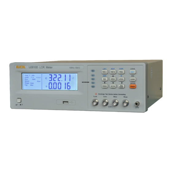
Chapter 2 Panel Description This chapter provides information including a tour of the front and rear panel and display area definition, which will help you to quickly learn how to operate the U2810D. A Tour of the Front Panel Figure 2-1 shows the brief description of each key on the U2810D’s front panel. - Page 10 Figure 2-2 Keybaord a) PAR A key: The primary function is the setup key of main test parameter. The secondary function is the sorting limits setup key LIMIT. b) PAR B key: The primary function is the setup key of second test parameter. The secondary function is the buzzer’s beep status setup key BEEP..
- Page 11 The second function is the automatic identification function key AI. h) CLEAR key: The primary function is the setup key of correction function. Under input status, it is the exit key [ESC]. RANGE key: The primary function is the setup key of range HOLD or AUTO. Under limit status , it is the left cursor key [ 30/100 key: The primary function is signal source output impedance setup key.
-
Page 12: A Tour Of The Rear Panel
A Tour of the Rear Panel Figure 2-3 shows a brief description of the U2810D’s rear panel. (1) Name Plate Name plate is used to provide the information of date, model, lot number and manufacturer etc. (2) Line Input Receptacle and Fuse Holder AC power cord receptacle. -
Page 13: Display Area Definition
Display Area Definition Figure 2-4 shows the display area definition of the U2810D LCD screen. Figure 2-4 Display Area Definition (1) Test Signal Frequency Indication “100 Hz” is on:The current test signal frequency is 100 Hz. “120 Hz” is on:The current test signal frequency is 120 Hz. - Page 14 “Hold” is off:Range HOLD (6) Trigger Mode Indication “Int” is on: Internal trigger mode “Man” is on: Manual trigger mode “Ext” is on: External trigger mode “Dut” is on: DUT trigger mode “Bus” is on: Bus trigger mode (7) Equivalent Circuit Mode Indication “...
- Page 15 (14) The Secondary Parameter Display Display the current measurement result of the secondary parameter. (15) The Secondary Parameter Indication Indicate the current measuring secondary parameter user selected. (16) The Secondary Function Indication “ ” is on: The current key function is the secondary function. “...
-
Page 16: Chapter 3 Operation
The Primary Function Operation 3.2.1 Measurement Function U2810D measures two components of the complex impedance parameters at the same time in a measurement cycle. The primary and secondary measurement parameters are listed as follows. -
Page 17: Test Frequency
6. Keep on pressing PAR B key, until the secondary parameter required is indicated. 3.2.2 Test Frequency U2810D provides 4 typical frequency points:100Hz, 120Hz, 1kHz and 10kHz. The current test frequency is displayed on the LCD. Perform the following steps to set the test frequency. -
Page 18: Measurement Speed
5. Keep on pressing LEVEL key, until the test signal level required is indicated on the LCD. 3.2.4 Measurement Speed U2810D provides 3 kinds of measurement speeds: Fast, Med and Slow. Generally, a slow measurement speed will result in more stable and accurate measurement results. Fast:... -
Page 19: Signal Source Output Impedance
Between above values: follow the manufacturer’s recommendation 3.2.6 Signal Source Output Impedance U2810D provides two different signal output impedance 30Ω and 100Ω. The measurement current through the DUT will be different with different signal output impedance under the test same signal voltage level. The current sensitive components, for example the inductors with cores, will get different measurement results under different signal source output impedance. -
Page 20: Measurement Range
(R, X) in serial with the device under test. Perform following steps for the open and short correction: 1. When the U2810D is under the measurement status, Press CLEAR key to enter the correction function. 2. If the fixture is open, the information shown in Figure 3-2 will be displayed. - Page 21 5. The OPEN correction is performed at all frequency points and ranges. The current frequency and range being corrected are displayed on the bottom of LCD. 6. U2810D judges the results of correction measurement automatically. If the current correction result is not correct, U2810D will interrupt the current correction operation and return to the measurement status.
- Page 22 It is not necessary to correction again under the same test conditions. U2810D selects the OPEN or SHORT correction operation according to the current measured impedance automatically. If there is a component in the test fixture or if the fixture is not shorted or opened reliably, “QUIT”...
-
Page 23: The Secondary Function Operation
3.3.2 Comparator Function U2810D’s built-in comparator can sort devices into a maximum of 4 bins (P1, P2, P3 and NG) using a maximum of three pairs of primary limits and one pair of secondary parameter limits. Also, a device whose primary parameter is within limits, but whose secondary... -
Page 24: Comparator Function On/Off
L, C, R, and Z can be inputted. Do not enter a value which is lower than the LOW limit in the tolerance sorting mode. If you do, the U2810D will never sort a device into the Bin you specified. The key functions under limits input status are described in table 3-3. - Page 25 Legend Description Set Auxiliary function;On or OFF Set tolerance mode;Per (percent tolerance)or Abs(Absolute tolerance ) Set nominal value of primary parameter Set the low limit value of P1 Set the high limit value of P1 Set the low limit value of P2 Set the high limit value of P2 Set the low limit value of P3 Set the high limit value of P3...
-
Page 26: Primary Parameter Display Mode
15. After all the sorting limits are inputted, press [ESC] key to return to the measurement status. 3.3.3 Primary Parameter Display Mode U2810D provides three kinds of display modes for the primary parameter: DIR: Direct reading display mode : Absolute deviation display mode ⊿... -
Page 27: Automatic Identification(Ai) Function
deviation display mode: ⊿ The difference between the measured value of the DUT and a previously stored reference value are displayed as a percentage of the reference value. The formula used to calculate the percent deviation is as follows. (X – Y)/ Y×100 [%] ⊿... -
Page 28: Chapter 4 Handler Interface
The comparison output signals include /P1, /P2, /P3, /AUX and /NG. Using these signals, the U2810D can easily be combined with a component handler and a system controller to fully automate component testing, sorting, and quality control data processing to increase production efficiency. - Page 29 Notice: The “/” (black slash) in front of the signal name means that the signal is asserted when LOW. Primary parameter High High Secondary parameter Figure 4-1 /P1, /P2, /P3, /AUX, /NG signal’s area example Contact assignment is described in Table 4-2, Pin assignment for handler interface connector is shown in Figure 4-2 and the timing diagram for handler interface is shown in Figure 4-3.
- Page 30 EXTV. /AUX Build-in pull-up resistance is 4.7kΩ. External Trigger: 12,13 /TRIG U2810D is triggered on the rising edge of a pulse applied to this pin. 14,15 No Connection Internal +5V voltage supply.(max. 0.3A) Generally, internal power supply is not recommended 16,17,18 to be used.
- Page 31 Figure 4-2 Pin Assignment for Handler Interface Connector 4-25...
- Page 32 T1 T2 /TRIG /IDX /EOM Data Previous data value Data value Measurement Time a measurement Trigger Delay Measurement Comparison Display Time Process Time Time Time Time Minimum Value Maximum Value T1 Trigger Pulse Width 10us ------ T2 Measurement Start Delay Time 200us Display time + 200us T3 Trigger wait time after...
-
Page 33: Electrical Characteristics
The /TRIG signal (pin 12 and 13) is connected to the cathode of the LED in an opto-coupler. The U2810D is triggered on the rising edge of the /TRIG pulse. The anode ot the LED can be powered from the internal +5V supply, or by an external voltage source (EXTV). - Page 34 Figure 4-4 Simplified Diagram of output and control signals Use the internal power: Pins 1 and 2 of the jumper J205 should be connected. Pins 1 and 2 of the jumper J204 should be connected. Use the external power (Factory default): Pins 2 and 3 of the jumper J205 should be connected.
-
Page 35: Chapter 5 Rs232C Serial Interface
Data Terminal Ready Transmitted Data Received Data Signal Ground Commom U2810D’s Serial Interface U2810D only used the smallest subset of the RS232C standard, the signals are listed as shown in Table 5-2. Table 5-2 U2810D Serial Signals Pin Number of 9 Function... -
Page 36: Serial Port Parameter
U2810D executes the command after the end character NL is received. 3) The character received by U2810D will be sent back to the controller again. The controller will not send the next character until the last return character is received correctively from U2810D. - Page 37 B. Check if the RS232 function is turned on and TALK ONLY function is turned off. C. When U2810D is executing a bus command, U2810D will not accept any character through the serial interface at the same time and the character sent by controller will be ignored.
-
Page 38: Chapter 6 The Specifications
Chapter 6 The Specifications The complete U2810D specifications are listed below. These specifications are the performance standards. When shipped from the factory, the U2810D meets the specifications listed in this section. Measurement Functions 1. Primary measurement parameters Inductance C: Capacitance... -
Page 39: Measurement Range
LC oscillator, then the parallel circuit mode should be selected. Measurement Range When U2810D is operated under 100Ω signal source output resistance, 5 ranges are available: 30Ω, 100Ω, 1kΩ, 10kΩ and100kΩ. When U2810D is operated under 30Ω signal source output resistance, 6 ranges are available: 10Ω, 30Ω, 100Ω, 1 kΩ, 10 kΩ... -
Page 40: Trigger Mode
Bus: When the measurement mode is set to “BUS”, U2810D performs a signal measurement every time the “TRIG IMM” command is sent to the U2810D via the RS232 interface. Measurement Terminals 4 Measurement Terminals :High current... -
Page 41: Maximum And Minimum Values Used For Accuracy Calculation
6.7.3 Measurement Voltage Level Factor kv 1.0Vrms: kv=0; 0.3Vrms: kv=1; 0.1Vrms: kv=4. 6.7.4 Measurement Frequency Factor kf kf=0; f ≤1kHz kf=0.5; f=10kHz Measurement Frequency U2810D provides 4 kinds of test frequencies: 100Hz, 120Hz, 1kHz and 10kHz. Accuracy: ±0.02% 6-35... -
Page 42: Test Signal Level
6.13 Comparator Function U2810D’s built-in comparator can short devices into a maximum of 4 bins (P1, P2, P3 and NG) using a maximum of three pairs of primary limits and one pair of secondary parameter limits. Also, a device whose primary parameter is within limits, but whose secondary parameter measurement result is not within limits can be sorted into an AUXiliary bin. -
Page 43: Ranging Mode
ASCII codes over the bus. 6.17 HANDLER interface U2810D can receive the Trigger signal and output the comparison results through the HANDLER interface. Synchronous signal /IDX and /EOM can be outputted. The output signals are logical low active and opto-isolated.
Need help?
Do you have a question about the U2810D and is the answer not in the manual?
Questions and answers