
Subscribe to Our Youtube Channel
Related Manuals for Monoprice 16102


Summary of Contents for Monoprice 16102
- Page 1 MONOPRICE Modular Video Wall System with Push-to-Pop-out and Anti-Theft Features P/N 16102 User's Manual...
-
Page 2: Table Of Contents
CONTENTS SAFETY WARNINGS AND GUIDELINES ............................3 INTRODUCTION ........................................ 4 FEATURES ..........................................5 CUSTOMER SERVICE ....................................6 PACKAGE CONTENTS ....................................6 REQUIRED TOOLS ......................................8 PRODUCT OVERVIEW ....................................9 PRODUCT DIMENSIONS ..................................10 MOUNT INSTALLATION ................................... 11 MULTIPLE MOUNT INSTALLATIONS ............................13 INSTALLING THE BRACKETS ................................ -
Page 3: Safety Warnings And Guidelines
SAFETY WARNINGS AND GUIDELINES Please read this entire manual before using this device, paying extra attention to these safety warnings and guidelines. Please keep this manual in a safe place for future reference. This wall mount is intended for indoor installations only. ... -
Page 4: Introduction
110 lbs (50kg). UL listed and backed by Monoprice's lifetime warranty and product support, rest assured that the Modular Video Wall Mount system is the best solution for... -
Page 5: Features
FEATURES... -
Page 6: Customer Service
If you have any problem with your order, please give us an opportunity to make it right. You can contact a Monoprice Customer Service representative through the Live Chat link on our website www.monoprice.com during normal business hours (Mon-Fri: 5am-7pm PT, Sat-Sun: 9am-... - Page 7 4x M5 x 16mm 4x M5 x 30mm Screws (A) Screws (B) 4x M6 x 16mm 4x M6 x 30mm Screws (C) Screws (D) 2x VESA Extension 4x TV Bracket 4x M8 x 16mm 4x M8 x 30mm Couplers (DD) Extenders (EE) Screws (E) Screws (F)
-
Page 8: Required Tools
6x 8 x 70 mm Lag 1x 1/2" Socket 6x Anchors (P) Bolts (O) Wrench (Q) REQUIRED TOOLS You will need the following tools for installation. Electronic Stud Finder Pencil Protective Eyewear Portable Drill 1/4" Drill Bit Carpenter's Level #2 Phillips Screwdriver 1/2"... -
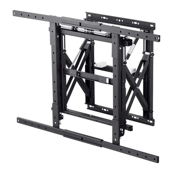
Page 9: Product Overview
PRODUCT OVERVIEW 1. Post-Installation Adjusters: Leveling, tilt, and in-out adjustment knobs make it easier than ever to flush and level the flat-panels for a seamless video wall. 2. Cable/Electrical Access: Allows for easy cable access and power distribution installations. 3. Kickstand: Prop up the flat-panel with the kickstand for easy maintenance. 4. -
Page 10: Product Dimensions
PRODUCT DIMENSIONS... -
Page 11: Mount Installation
MOUNT INSTALLATION Perform the following steps to install this wall mount. 1. Use a stud finder to locate two adjacent wall studs. Use a pencil to mark the exact center of each stud. 2. Two people are required for this step. Hold the mount against the wall. - Page 12 4. Place a 5/16" washer (N) onto one of the 5/16" x 3" lag bolts (O), then insert it in one of the mounting holes and tighten it with a 1/2" socket wrench. Do not over tighten the bolt. 5. Use a carpenter's level to level the mount again then mark the three remaining mounting hole locations.
-
Page 13: Multiple Mount Installations
7. Place a 5/16" washer (N) onto one of the 5/16" x 3" lag bolts (O), then insert it in one of the mounting holes and tighten it with a 1/2" socket wrench. Repeat with the other lag bolts. Do not over tighten the bolts. MULTIPLE MOUNT INSTALLATIONS If you will be installing multiple mounts in a video wall, draw horizontal and vertical lines to mark the locations for additional mounts, as shown in the following images. -
Page 14: Installing The Brackets
INSTALLING THE BRACKETS Refer to the section conforming to the VESA mounting size of your display. 100x100 ~ 400x400 1. Place your display face down on a blanket or towel. 2. If the bracket (BB) fits flush against the VESA holes, mount the brackets to the display as shown in image (a) below, otherwise, mount them as shown in image (b). -
Page 15: 600X400 ~ 900X400
600x400 ~ 900x400 1. Assemble the horizontal extensions, as shown in image (1), then attach the brackets to the extensions as shown in image (2). 2. Place your display face down on a blanket or towel. -
Page 16: 600X600 ~ 900X600
3. Mount the bracket assembly to the display, as shown in the image below. 600x600 ~ 900x600 1. Assemble the horizontal extensions, as shown in image (1). - Page 17 2. Attach the vertical extensions to the brackets, as shown in image (2). 3. Attach the brackets to the horizontal extensions, as shown below. 4. Place your display face down on a blanket or towel.
- Page 18 5. Mount the bracket assembly to the display, as shown in the image below.
-
Page 19: Attaching The Brackets To The Mount
ATTACHING THE BRACKETS TO THE MOUNT 1. With the help of an assistant, lift the display and hook the brackets onto the mount, as shown in the image below. 2. Locate the pre-installed security locking safety screw at the bottom of each bracket. -
Page 20: Post-Installation Adjustments
POST-INSTALLATION ADJUSTMENTS Use the adjustment points indicated in the image below to fine tune the display location. MAINTENANCE AND SERVICE Perform the following steps to access the rear of an installed display for maintenance. 1. Push evenly on the display to release the dual latch spring lock. - Page 21 2. Slowly pull the display to extend the scissor arms. 3. Loosen the locking safety screws on both mounting brackets. 4. Tilt up the bottom of the display, then set the kickstands against the bottom of the mount, as shown in the image below.
Need help?
Do you have a question about the 16102 and is the answer not in the manual?
Questions and answers