Table of Contents
Advertisement
Quick Links
Advertisement
Table of Contents

Related Manuals for UNICORECOMM UM960


Summary of Contents for UNICORECOMM UM960
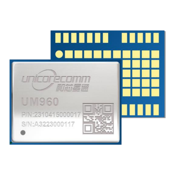
- Page 1 UM960 User Manual INSTALLATION AND OPERATION USER MANUAL WWW.UNICORECOMM.COM UM960 GPS/BDS/GLONASS/Galileo/QZSS All-constellation Multi-frequency Module High Precision RTK Positioning Copyright© 2009-2022, Unicore Communications, Inc. Data subject to change without notice.
- Page 2 UM960 User Manual Revision History Version Revision History Date R1.0 First release Sep., 2022...
- Page 3 Unicore holds the trademarks of “和芯星通”,“UNICORECOMM” and other trade name, trademark, icon, logo, brand name and/or service mark of Unicore products or their product serial referred to in this manual (collectively “Unicore Trademarks”).
- Page 4 UM960 User Manual Foreword This document describes the information of the hardware, package, specification and the use of Unicore UM960 modules. Target Readers This document applies to technicians who possess the expertise on GNSS receivers.
-
Page 5: Table Of Contents
Contents Introduction .................... 1 1.1 Key Features ........................2 1.2 Key Specifications ......................2 1.3 Interfaces ......................... 4 Hardware ....................5 2.1 Dimensions ........................5 2.2 Pin Definition ........................7 2.3 Electrical Specifications ....................9 2.3.1 Absolute Maximum Ratings ..................9 2.3.2 Operational Conditions .................... -
Page 6: Introduction
UM960 User Manual 1 Introduction UM960 is a new generation of GNSS high precision positioning RTK module from Unicore. It supports all constellations and multiple frequencies, and can simultaneously track BDS B1I/B2I/B3I + GPS L1/L2/L5 + GLONASS L1/L2+Galileo E1/E5a/E5b + QZSS L1/L2/L5 + SBAS. -
Page 7: Key Features
Key Features High precision, compact size and low power consumption Based on the new generation GNSS SoC -NebulasIV , with RF-baseband and high precision algorithm integrated 16.0 mm × 12.2 mm × 2.6 mm, surface-mount device Supports all-constellation multi-frequency on-chip RTK positioning solution ... - Page 8 UM960 User Manual Observation Accuracy(RMS) GLONASS Galileo B1I/ L1C/A /G1/E1 Pseudorange 10 cm 10 cm 10 cm 10 cm 1 mm 1 mm 1 mm 1 mm B1I/ L1C/A /G1/E1 Carrier Phase B2I/L2P/G2/E5b Pseudorange 10 cm 10 cm 10 cm...
-
Page 9: Interfaces
NebulasIV SoC NebulasIV is UNICORECOMM’s new generation high precision GNSS SoC with 22 nm low power design, supporting all constellations, multiple frequencies and 1408 super channels. It integrates a 2 GHz dual CPU, a high speed floating point processor and an RTK co-processor, which can fulfill the high precision baseband processing and RTK positioning independently. -
Page 10: Hardware
UM960 User Manual 2 Hardware Dimensions Table 2-1 Dimensions Symbol Min.(mm) Typ. (mm) Max. (mm) 15.80 16.00 16.50 12.00 12.20 12.70 2.40 2.60 2.80 0.90 1.00 1.10 0.20 0.30 0.40 1.40 1.50 1.60 1.00 1.10 1.20 0.70 0.80 0.90 3.20 3.30... - Page 11 φ Figure 2-1 UM960 Mechanical Dimensions Hardware UC-00-M34 EN R1.0...
-
Page 12: Pin Definition
UM960 User Manual Pin Definition Figure 2-2 UM960 Pin Definition Table 2-2 Pin Definition Description Reserved, must be floating; cannot connect — ground or power supply or peripheral I/O Reserved, must be floating; cannot connect — ground or power supply or peripheral I/O... - Page 13 Description VCC_RF External LNA power supply — Ground ANT_IN GNSS antenna signal input — Ground — Ground RTK_STAT: High level, RTK Fix; Low level, RTK No Fix LAN_EN: High level, enable external LNA; RTK_STAT/LAN_EN Low level, disable external LNA; Note: The pin function is configured by protocol. The default is RTK_STAT.
-
Page 14: Electrical Specifications
UM960 User Manual Electrical Specifications 2.3.1 Absolute Maximum Ratings Table 2-3 Absolute Maximum Ratings Parameter Symbol Min. Max. Unit Power Supply (VCC) -0.3 Voltage Input -0.3 GNSS Antenna Signal Input ANT_IN -0.3 RF Input Power ANT_IN input Consumption of Antenna... -
Page 15: Operational Conditions
2.3.2 Operational Conditions Table 2-4 Operational Conditions Parameter Symbol Min. Typ. Max. Unit Condition Power Supply (VCC) Maximum Ripple Voltage Working Current VCC = 3.3 V VCC_RF Output Voltage VCC_RF VCC-0.1 VCC_RF Output Current ICC_RF Operating Temperature ° C Power Consumption 2.3.3 IO Threshold Table 2-5 IO Threshold Parameter... -
Page 16: Hardware Design
3 Hardware Design Antenna Feed Design UM960 just supports feeding the antennal from the outside of the module rather than the inside. It is recommended to use devices with high power and that can withstand high voltage. Gas discharge tube, varistor, TVS tube and other high-power protective devices may also be used in the power supply circuit to further protect the module from lighting strike and surge. -
Page 17: Grounding And Heat Dissipation
Grounding and Heat Dissipation Grounding and heat dissipation pad Figure 3-2 Grounding and Heat Dissipation Pad The 55 pads in the rectangle in Figure 3-2 are for grounding and heat dissipation. In the PCB design, they must connect to a large sized ground to strengthen the heat dissipation. -
Page 18: Production Requirement
UM960 User Manual 4 Production Requirement Recommended soldering temperature curve is as follows: Rising Preheating Reflux Cooling ° C Peak 245 ° C 40 to 60s 60 to120s Max. 4° C/s Max. 3° C/s Time (s) Figure 4-1 Soldering Temperature (Lead-free) Temperature Rising Stage ... - Page 19 In order to prevent falling off during soldering of the module, do not solder it on the back of the board during design, that is, better not go through soldering cycle twice. The setting of soldering temperature depends on many factors of the factory, ...
-
Page 20: Packaging
Figure 5-1 Label Description Product Packaging The UM960 module uses carrier tape and reel (suitable for mainstream surface mount devices), packaged in vacuum-sealed aluminum foil antistatic bags, with a desiccant inside to prevent moisture. When using reflow soldering process to solder modules, please strictly comply with IPC standard to conduct humidity control. - Page 21 Thickness: 2.0 mm Carrier Tape Space between (center-to-center distance): 20 mm The UM960 is rated at MSL level 3. Refer to the relevant IPC/JEDEC J-STD-033 standards for the package and operation requirements. You may access to the website www.jedec.org to get more information.
- Page 22 和芯星通科技(北京)有限公司 Unicore Communications, Inc. 北京市海淀区丰贤东路 7 号北斗星通大厦三层 F3, No.7, Fengxian East Road, Haidian, Beijing, P.R.China, 100094 www.unicorecomm.com Phone: 86-10-69939800 Fax: 86-10-69939888 info@unicorecomm.com...
Need help?
Do you have a question about the UM960 and is the answer not in the manual?
Questions and answers