
Related Manuals for UNICORECOMM UM4B0


Summary of Contents for UNICORECOMM UM4B0
- Page 1 UM4B0 GPS/BDS/GLONASS/Galileo Four- System Undeca-Frequency High Precision RTK Module...
- Page 2 Revision History Version Revision History Date Ver. 1.0 First Edition Feb. 2017 R3.1 Add the related description to clarify 2019-08-22 the VCC restrictions R3.2 Chapter 2.2: add the working current 2019-09-18 info of No.17 pin Disclaimer Information in this document is subject to change without notice and does not represent a commitment on the part of Unicore Communications, Inc.
- Page 3 Foreword This <User Manual> offers you information in the features of the hardware, the installation, specification and use of Unicore UM4B0 product. For the generic version of this manual, please refer to different part of the manual according to your purchased product configuration, concerning CORS, RTK and Heading.
-
Page 4: Table Of Contents
LECTRICAL PECIFICATIONS ........................8 PERATION ONDITION ........................8 HYSICAL PECIFICATIONS 3 HARDWARE DESIGN ................9 ........................ 9 ESIGN IN ONSIDERATIONS UM4B0 R ......................10 EFERENCE ESIGN .............................. 11 PCB P ..........................13 ACKAGING ..........................13 ESET IGNAL ............................13 NTENNA 4 INSTALLATION AND CONFIGURATION .......... -
Page 5: Introduction
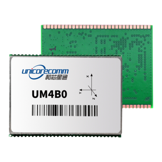
UM4B0 User Manual 1 Introduction 1.1 Overview UM4B0 is the high precision positioning and heading RTK module developed by Unicore Communications, targeting light Robots, UAVs, intelligent vehicles, GIS information collection, etc. By employing a single UC4C0(432 channel tracking) baseband chip and a single RF chip, using single-sided SMD packaging, UM4B0 can achieve smallest size(30x40mm) among industry with high accuracy heading and positioning output. -
Page 6: Technical Specifications
1.3 Technical Specifications Table 1-1 Performance Specifications 432 channels, based on Nebulas-II SoC <5s (typical) Channels Initialization chip time GPS L1/L2/L5 >99.9% Frequency Initialization BDS B1/B2/B3 reliability GLONASS L1/L2 Galileo E1/E5a/E5b Single point Time to First Cold start<25s Horizontal:1.5m positioning Fix (TTFF) Reacquisition <1s... -
Page 7: Interfaces
4. 1PPS UM4B0 outputs 1 PPS with adjustable pulse width and polarity. 5. Event UM4B0 provides 1 Event Mark Input with adjustable pulse width and polarity. -
Page 8: Hardware
2 Hardware 2.1 Dimensions Table 2-1 Dimensions Symbol Value (mm) Tolerance (mm) 40.00 -0.2 +0.5 30.00 ±0.2 ±0.2 4.00 ±0.1 1.58 1.27 ±0.1 1.07 Figure 2-1Mechanical Dimensions... -
Page 9: Pin Definition And Ins Coordinate System
UM4B0 User Manual 2.2 Pin Definition and INS Coordinate System (Top View) Figure 2-2 UM4B0 Pin Diagram Table 2-2 Pin Definition Description Ground ANT_IN GNSS antenna signal input Ground Ground ANT_PWR GNSS antenna power supply Ground ANT_NLOD GNSS antenna open circuit indicator... - Page 10 Description Ground SPEED odometer- pulse odometer- direction V_BACKUP When the main power supply of the module VCC is cut off, V_BCKP supplies power to RTC and SRAM. Level requirements: 2.0~ 3.6 V, and the working current is about 10uA. Can be suspended without using the hot start function Ground PVT STAT...
-
Page 11: Electrical Specifications
UM4B0 User Manual Description TXD2 COM 2 transmit RXD2 COM 2 receive TXD3 COM 3 transmit RXD3 COM 3 receive I2C_SDA I2C data I2C_SCL I2C clock Ground Pulse per second EVENT Event Mark RST_N Fast reset, will not clear user configurations. -
Page 12: Operation Condition
2.4 Operation Condition Table 2-4 Operation Condition Item Min. Typical Max. Unit Condition Value Power Supply (VCC) Pulse current* Iccp Vcc = 3.3 V LOW Level Input Vin_low_1 -0.3 VCC*0.3 V Voltage High Level Input Vin_high_1 VCC*0.7 VCC+0.3 V Voltage LOW Level Output Vout_low 0.45... -
Page 13: Hardware Design
3 Hardware Design 3.1 Design in Considerations To make UM4B0 to work properly, you need to properly connect the following: The module VCC power-on has good monotone, the initial level is lower than 0.4V, and the undershoot and ringing should be guaranteed within 5% VCC ... -
Page 14: Um4B0 Reference Design
Interfaces: Ensure that the signals and baud rate of main equipment match UM4B0 module’s Antenna interface: Make sure the antenna impedance matching, and the circuit is short and smooth, try to avoid acute angle Try to avoid circuits below UM4B0 ... -
Page 15: Pins
UM4B0 User Manual Figure 3-2 UM4B0 Reference Design 3.3 Pins Table 3-1 Pin Notes Pin Name Description Notes Power Power Voltage Stable, clear low ripple power 31,32 Supply Supply supply, peak ripple power lower than 50mVpp is preferred ANT_PWR Power Antenna... - Page 16 Pin Name Description Notes 57, 58, Antenna ANT_IN Satellite 50 Ω impedance matching signal input COM1 COM1 output, leave UART TXD1 Transmit unconnected if no use Data COM1 COM1 input, leave unconnected RXD1 Receive if no use Data COM2 COM2 output, leave TXD2 Transmit unconnected if no use...
-
Page 17: Pcb Packaging
Figure 3-3 UM4B0 recommended PCB Packaging(unit:mil,in brackets:mm) 3.5 Reset Signal UM4B0 module can’t work properly unless it is correctly reset after power on. To ensure effective reset, the reset pin (RST) and power supply pin (VCC) must meet the following time sequence. -
Page 18: Installation And Configuration
Figure 3-5 UM4B0 Active Antenna Connection 4 Installation and Configuration 4.1 ESD Handling Precautions UM4B0 Module is Electrostatic Sensitive Devices (ESD) device and requires special precautions when handling. Electrostatic discharge may cause damages to the device. All operations mentioned in this chapter shall be carried out in an antistatic workbench, using both wearing an antistatic wrist strap and a conductive foam pad. -
Page 19: Hardware Installation
Step 1: Make sure to make full anti-static measures, such as anti-static wrist strap, grounding the workbench; Step 2: Align UM4B0 transfer board positioning holes and pins with EVK, and fix it in the EVK. EVK provides power supply and standard communication interface for the module, to communicate with peripheral devices;... - Page 20 Figure 4-2 Installation Instruction Step 3: Select the GNSS antenna with appropriate gain, fix it in the stable, non-block area, using the coaxial radio frequency cable to connect the antenna with UM4B0 EVK; Step 4: Connect the PC to the EVK serial port through direct serial cable;...
-
Page 21: Start Up
4.3 Start Up The power supply for UM4B0 is 3.3VDC, before powering on the device, please connect UM4B0 serial port to the GNSS antenna. The receiver is started and the communication is connected after powering up. Testing tools are available for module testing. -
Page 22: Operation Procedures
Selecting and recording the log Sending commands to the Receiver Operating and configuration the ASCII view The trajectory view for displaying the present point and the past point of the Receiver Switching Views over the tracking window ... -
Page 23: Configuration Commands
All commands are composed of a log heading and configuration parameters (parameters can be null, then there is only one heading in the command). Header field contains the command name or message headers. UM4B0 is simple to use, common instructions as shown in the following table: Command... - Page 24 Command Description GPS, GLONASS can be disabled separately mask -GPS Unmask (enable) the satellite systems for tracking. BDS, GPS, GLONASS can be Enabled separately. By default, all satellite systems are enabled. config com1 115200 Set the baud rate of com1 to 115200. Baud rates of com1 com2 and com3 can be set to any of the following: 9600, 19200, 38400, 57600, 115200, 230400,460800...
-
Page 25: Rtk Reference Station Configuration
UM4B0 User Manual Command Description NMEA0183 Output Message gpgga comx 1 Output GGA in 1Hz. Time, position and fix-related data of the GPS receiver. Message type and update rate can be set by oneself. The corresponding output frequency rate for 1, 0.2, 0.1 are 1hz, 5hz, 10hz;... -
Page 26: Rtk Rover Configuration
5.2 RTK Rover Configuration RTK Rover stations (rover station) receive differential correction data sent from reference stations, at the same time receive satellite signals, make RTK positioning solution, to achieve RTK precision positioning to achieve cm or mm-level accuracy. Common instructions for configuring RTK Rover are as follows: gngga 1 saveconfig 5.3 Moving Base Configurations... -
Page 27: Antenna Detection
7 Inertial Navigation UM4B0 has built in inertial navigation devices, please follow the instructions in the Reference Commands Manual for High Precision GNSS Boards to configure the installation angle of the Board to match the Board coordinate and the vehicle’s coordinate, to make sure the inertial components work properly. -
Page 28: Firmware Upgrade
Figure 7-2 UM4B0 xyz Coordinate 8 Firmware Upgrade Uprecise software is used for the remote update of UM4B0, please follow the steps below to upgrade the device: Figure 8-1 Update Interface Click “…” to browse the firmware update package, and click “Start” to start the firmware... - Page 29 UM4B0 User Manual Figure 8-2 Update Steps Waiting for the process to complete 100%,(the upgrade time is normally within 5min): Figure 8-3 Update Steps Please use COM1 only to update firmware.
-
Page 30: Production Requirement
9 Production Requirement Recommended welding thermal cycle curve is as follows: Figure 9-1 Soldering Temperature Temperature rising Stage Rising slope: Max. 3℃/s Rising temperature range:50℃-150℃ Preheating stage Preheating time: 60 – 120 s Preheating temperature range: 150 - 180℃ Reflux Stage ... -
Page 31: Packaging
Board. 10 Packaging UM4B0 modules are delivered in trays, which is suitable for mainstream SMT equipment. Each box contains 5 trays, so 150 UM4B0 modules are packaged in the box. Table 10-1 Package Information Description... - Page 32 和芯星通科技(北京)有限公司 Unicore Communications, Inc. 北京市海淀区丰贤东路7号北斗星通大厦三层 F3, No.7, Fengxian East Road, Haidian, Beijing, P.R.China, 100094 www.unicorecomm.com Phone: 86-10-69939800 Fax: 86-10-69939888 info@unicorecomm.com www.unicorecomm.com...
Need help?
Do you have a question about the UM4B0 and is the answer not in the manual?
Questions and answers