Table of Contents
Advertisement
Quick Links
AT-START-F435 User Manual
Getting started with AT32F435ZMT7
Introduction
AT-START-F435 is designed to help you explore the high performance of the 32-bit microcontroller
®
AT32F435 that embeds ARM Cortex
-M4 core with FPU, and expedite application development.
AT-START-F435 is an evaluation board based on AT32F435ZMT7 microcontroller. The device
contains such peripherals as LEDs, buttons, two USB micro-B connectors, type-A connector,
TM
Arduino
Uno R3 extension interfaces and 16 MB SPI Flash memory (extended through QSPI1).
This evaluation board embeds AT-Link-EZ for debugging/programming without the need of other
development tools.
2021.11.20
1
Rev 1.00
www.arterytek.com
Advertisement
Table of Contents

Related Manuals for ARTERY AT-START-F435


Summary of Contents for ARTERY AT-START-F435
- Page 1 AT-START-F435 User Manual Getting started with AT32F435ZMT7 Introduction AT-START-F435 is designed to help you explore the high performance of the 32-bit microcontroller ® AT32F435 that embeds ARM Cortex -M4 core with FPU, and expedite application development. AT-START-F435 is an evaluation board based on AT32F435ZMT7 microcontroller. The device...
-
Page 2: Table Of Contents
Features ........................5 Definition of terms ....................5 Quick start ......................6 Get started........................ 6 AT-START-F435 development toolchains ..............6 Hardware and layout ..................... 7 Power supply selection ..................... 9 IDD ........................... 9 Programming and debugging: embedded AT-Link-EZ ..........9 Boot mode selection .................... - Page 3 AT-START-F435 User Manual List of tables Table 1. Boot mode selection jumper settings ................... 10 Table 2. 0Ωresistor settings ....................... 12 Table 3. Arduino Uno R3 extension interface pin definition ............13 Table 4. Document revision history ....................19 2021.11.20...
- Page 4 AT-START-F435 User Manual List of figures Figure 1. Hardware block diagram ...................... 7 Figure 2. Top layer ..........................8 Figure 3. Bottom layer ......................... 8 Figure 4. Schematic (AT-Link-EZ) ..................... 15 Figure 5. Schematic (microcontroller) ....................16 Figure 6. Schematic (power supply and peripherals) ................ 17 Figure 7.
-
Page 5: Overview
AT-START-F435 User Manual Overview Features has the following characteristics: AT-START-F435 ® AT-START-F435 has an on-board AT32F435ZMT7 microcontroller that embeds ARM Cortex M4F 32-bit core with FPU, 4032 KB Flash memory and 384 KB SRAM, in LQFP144 packages. On-board AT-Link interface: −... -
Page 6: Quick Start
AT-START-F435 User Manual Quick start Get started Configure the AT-START-F435 board in the following sequence: 1. Check the Jumper’s position on board: JP1 is connected to GND or OFF (BOOT0 = 0, and BOOT0 has an pull-down resistor in the AT32F435ZMT7);... -
Page 7: Hardware And Layout
AT-START-F435 User Manual Hardware and layout AT-START-F435 board is designed around an AT32F435ZMT7 microcontroller in LQFP144 package. Figure 1 shows the connections between AT-Link-EZ, AT32F435ZMT7 and their peripherals (buttons, LEDs, USB OTG, SPI and extension connectors) Figure 2 Figure 3 shows their respective locations on the AT-Link-EZ and AT-START-F435 board. -
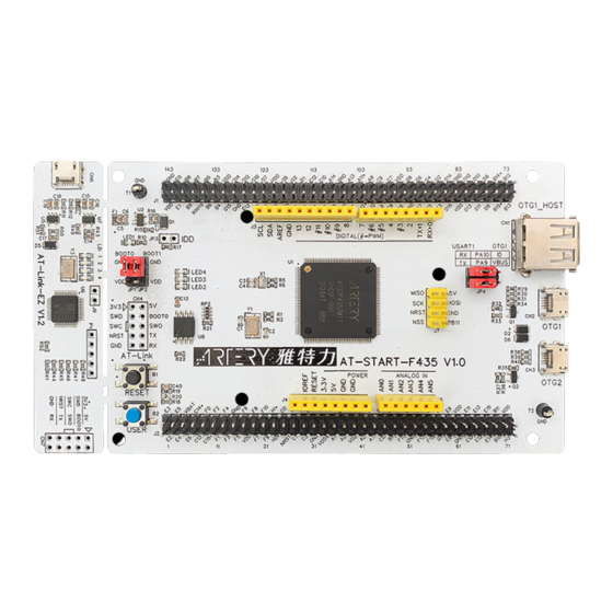
Page 8: Figure 2. Top Layer
AT-START-F435 User Manual Figure 2. Top layer LQFP144 I/O User LED QSPI Flash AT32F435ZMT7 extension interface Jumper for I Arduino Uno LEXT 32.768 kHz Jumper for USART1 and OTG1 measurement extension interface crystal Power LED Jumper for boot mode select... -
Page 9: Power Supply Selection
5 V power supply (E5V). Then 5 V power provides 3.3 V for the microcontroller and its peripherals using on-board 3.3 V voltage regulator (U2). 5 V pin of J4 or J7 can also be used as an input power, so the AT-START-F435 board can be supplied through a 5 V power unit. -
Page 10: Boot Mode Selection
AT-START-F435 User Manual Boot mode selection At startup, three different boot modes are available for selection through pin configuration. Table 1. Boot mode selection jumper settings Pin configuration Jumper Boot mode BOOT1 BOOT0 JP1 to GND or be OFF Boot from internal Flash memory (factory default setting) -
Page 11: Leds
The device is powered via USB micro-B interface, which is done by PH3 and PB10 controlling SI2301 switch. AT-START-F435 board has a USB type-A extension interface (CN1). This is a OTGFS1 host interface for connecting to U disk and other devices, without the need of USB OTG cable. The USB type-A interface has no power switch control. -
Page 12: Resistors
AT-START-F435 User Manual 0Ω resistors 3.10 Table 2. 0Ωresistor settings Resistors State Description When JP3 OFF, 3.3V is connected to the microcontroller (MCU power power to supply microcontroller. consumption When JP3 OFF, 3.3V can be connected to an ammeter to measurement) measure the power consumption of the microcontroller. -
Page 13: Extension Interfaces
Female plug J3~J6 and male plug J7 support Arduino Uno R3 connector. Most of the daughter boards built on Arduino Uno R3 are applicable to AT-START-F435 board. Note: The I/Os of the AT32F435ZMT7 are 3.3 V-compatible with Arduino Uno R3, but not 5 V. -
Page 14: 3.11.2 Lqfp144 I/O Extension Interface
Table 2 3.11.2 LQFP144 I/O extension interface The I/Os of AT-START-F435 microcontroller can be connected to external devices through extension interfaces J1 and J2. All I/Os on the AT32F435ZMT7 are available on these extension interfaces. J1 and J2 can also be measured with oscilloscope, logic analyzer or voltmeter probe. -
Page 15: Schematic
AT-START-F435 User Manual Schematic Figure 4. Schematic (AT-Link-EZ) Refer to AT_START_F435_V1.0_SCH.pdf 2021.11.20 Rev 1.00... -
Page 16: Figure 5. Schematic (Microcontroller)
AT-START-F435 User Manual Figure 5. Schematic (microcontroller) Refer to AT_START_F435_V1.0_SCH.pdf 2021.11.20 Rev 1.00... -
Page 17: Figure 6. Schematic (Power Supply And Peripherals)
AT-START-F435 User Manual Figure 6. Schematic (power supply and peripherals) Refer to AT_START_F435_V1.0_SCH.pdf 2021.11.20 Rev 1.00... -
Page 18: Figure 7. Schematic (Extension Interfaces)
AT-START-F435 User Manual Figure 7. Schematic (extension interfaces) Refer to AT_START_F435_V1.0_SCH.pdf 2021.11.20 Rev 1.00... -
Page 19: Revision History
AT-START-F435 User Manual Revision history Table 4. Document revision history Date Revision Changes 2021.11.20 1.00 Initial release 2021.11.20 Rev 1.00... - Page 20 Purchasers hereby agrees that Artery’s products are not authorized for use as, and purchasers shall not integrate, promote, sell or otherwise transfer any Artery’s product to any customer or end user for use as critical components in (a) any medical, life saving or life...
Need help?
Do you have a question about the AT-START-F435 and is the answer not in the manual?
Questions and answers