Table of Contents
Advertisement
Quick Links
Advertisement
Table of Contents

Related Manuals for Gewiss Chorus Digital Vision


Summary of Contents for Gewiss Chorus Digital Vision
- Page 1 Video Entryphone Technical Manual...
- Page 2 IEC 60364, or the European harmonization document HD 60364. Gewiss sales organization is ready to provide full explanations and technical data on request. Gewiss and Chorus are trademarks of Gewiss SpA.
-
Page 3: Table Of Contents
Connecting the video entryphone devices LAN network Apartment with several apartment units Front door unit modules Vision Master Chorus Signal extension and long distances Powering the devices Connecting the outdoor devices Apartment unit Front door unit Telecameras Chorus Digital Vision - Technical System Manual... - Page 4 Removing a secondary front door unit manually Removing a secondary front door unit via PC Removing an apartment unit manually Removing an apartment via PC Removing a camera interface or relay unit manually Chorus Digital Vision - Technical System Manual...
- Page 5 (GW 18 341 TB - GW 18 341 VT - GW 18 341 VA - GW 18 343 TB - GW 18 343 VT - GW 18 343 VA) Wall-mounting entryphone (GW 18 360) Chorus Digital Vision - Technical System Manual...
- Page 6 Frames for front door unit (GW 18 121, GW 18 122, GW 18 123) Flush-mounting box for video entryphone (GW 24 237) Flush-mounting box for Vision Master Chorus (GW 24 101) Flush-mounting box for entryphone with speakerphone (GW 24 403) Chorus Digital Vision - Technical System Manual...
-
Page 7: The System
Internal number busy: the system indicates to the person calling if the internal number is already busy with another communication. Privacy: by activating this apartment unit function, any incoming call will automatically obtain the "busy" signal and the occupant will not Chorus Digital Vision - Technical System Manual... - Page 8 Night&Day operating mode to transfer calls from the front door units to the porter's desk. (*) The porter's desk software can only be used with audio/video apartment units (GW 18 341xx, GW 18 343xx, GW 18 000xx). Chorus Digital Vision - Technical System Manual...
-
Page 9: System Architecture
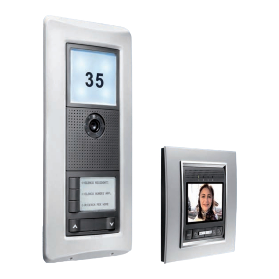
Makes it possible to call and communicate with a specific apartment unit. Available in colour audio/video or audio only versions, selecting the called position using push-buttons or an electronic index. For wall-mounting or flush-mounting installation. Chorus Digital Vision - Technical System Manual... -
Page 10: Maximum System Expansion
(backlit with a white light) for calling two separate apartments. Audio module for front door unit (GW 18 311) The same characteristics as the Audio/video module for front door unit (GW 18 301), but without the telecamera. Chorus Digital Vision - Technical System Manual... - Page 11 Boxes for the flush-mounting assembly of the front door unit. Available for one (GW 18 131), two (GW 18 132) or three (GW 18 133) modules. Up to 3 boxes can be combined (for a maximum of 9 modules), using the special coupling elements supplied. Chorus Digital Vision - Technical System Manual...
-
Page 12: Devices And Accessories For Apartment Units
The video entryphone has an input for a local push-button (call from landing) and a relay output for a local implementation. The last letters of the product code indicate the colour of the finish plate: VT = titanium, VA = slate, TB = white. Chorus Digital Vision - Technical System Manual... -
Page 13: System Components
Single audio/video power supply unit - DIN rail (GW 18 361) This device provides the supply current (SELV - Safety Extra Low Voltage - 14.4V DC rated) to the devi- ces of the video entryphone system. It has a single 18 VA output. Chorus Digital Vision - Technical System Manual... - Page 14 LAN video entryphone network and display the images on any video entryphone with speakerphone (GW 18 341 xx, GW 18 343 xx) or Vision Master Chorus (GW 18 000 xx). Chorus Digital Vision - Technical System Manual...
-
Page 15: Software
file The latest version of the software can be downloaded, free of charge, from the website: www.gewiss.com/irj/portal/gwvct_IT Chorus Digital Vision - Technical System Manual... -
Page 16: Design
1) In the case of a single-family system, there is another (reduced) configuration requiring only a front door unit, a single apartment unit, and the power supply unit, but a special cable is needed to connect the front door and apartment units. Chorus Digital Vision - Technical System Manual... -
Page 17: Dimensions And Maximum Extension Of The System
NB: for further information about how to increase the distance between the devices, refer to Signal extension and long distances. ATTENTION: for the maximum voltages and currents allowed on the relays, refer to the technical specifications of the individual devices. Chorus Digital Vision - Technical System Manual... -
Page 18: Positioning The Front Door Unit
120-125cm from the floor; the standard height (160-165cm) does not prevent the apartment unit being used by disabled people, but it does make it more difficult for them. Chorus Digital Vision - Technical System Manual... -
Page 19: Positioning The Other System Devices
To ensure the correct functioning of the system, you are advised to lay the DIGITAL VISION system cables and the energy cables in separate cable paths. If you need to pass the DIGITAL VISION cable and the energy cable in the same path (same conduit), the only Gewiss cable you can use is the GW 38 195. -
Page 20: System Composition
Important: if several primary front door units are associated with an apartment unit in "free" mode, the electro-lock command only acts on the main primary front door unit (the first position programmed). Chorus Digital Vision - Technical System Manual... -
Page 21: Determining The Necessary Number Of Switches
12 apartment units (connections) ÷ 4 = 3 switches for the second building 3 front door units ÷ 2 = 1,5 (which, rounded up, means 2 switches). The overall requirement is therefore 4 + 3 + 2 = 9 switches Chorus Digital Vision - Technical System Manual... -
Page 22: Determining The Necessary Number Of Power Supplies
The only rule to be observed is that the main module (GW 18 301, GW 18 302, GW 18 311, GW 18 312) must always be at the top. The front door unit may consists of up to 3 boxes containing 3 modules. Chorus Digital Vision - Technical System Manual... - Page 23 5-6 apartments 7-8 apartments 9-10 apartments 11-12 apartments 13-14 apartments 15-16 apartments 17-18 apartments 19-20 apartments 21-22 apartments 23-24 apartments 25-26 apartments 27-28 apartments 29-30 apartments 31-32 apartments 1...160 apartments 1...160 apartments 33-34 apartments Chorus Digital Vision - Technical System Manual...
- Page 24 311) or the Audio module with 2 push-buttons for front door unit (GW 18 312) instead of the equivalent Audio/video module for front door unit (GW 18 301) and the Audio/video module with 2 push-buttons for front door unit (GW 18 302). Chorus Digital Vision - Technical System Manual...
-
Page 25: Connection Diagrams
To connect the various devices, you can use the LAN cables GW 38 189 (cat. 5e UTP for indoor laying) and GW 38 195 (cat. 5e UTP for outdoor laying), or the equivalent cables available on the market. Chorus Digital Vision - Technical System Manual... -
Page 26: Two-Family Video Entryphone Kit
To connect the various devices, you can use the LAN cables GW 38 189 (cat. 5e UTP for indoor laying) and GW 38 195 (cat. 5e UTP for outdoor laying), or the equivalent cables available on the market. Chorus Digital Vision - Technical System Manual... -
Page 27: Video Entryphone System - 160 Apartments, 1 Upright
230V AC 230V AC GW 18 341 XX PoL 1 PoL 2 LAN 1 Vout PoL 3 PoL 4 LAN 2 GW 18 341 XX GW 18 371 GW 18 361 230V AC Chorus Digital Vision - Technical System Manual... - Page 28 The PC must be equipped with the system configuration software and must be connected to the video entryphone system via the LAN port of an ethernet switch or, alternatively, a switched OFF PoL port. Chorus Digital Vision - Technical System Manual...
-
Page 29: Video Entryphone System - 160 Apartments, 7 Uprights
LAN 2 LAN 2 PoL 3 PoL 4 PoL 3 PoL 4 GW 18 371 GW 18 361 GW 18 371 GW 18 361 GW 18 361 230V AC 230V AC 230V AC Chorus Digital Vision - Technical System Manual... - Page 30 FRONT DOOR UNIT 3 PoL 1 PoL 2 LAN 1 Vout PoL 3 PoL 4 LAN 2 GW 18 371 GW 18 361 230V AC PRIMARY FRONT DOOR UNIT SECONDARY FRONT DOOR UNIT 1 Chorus Digital Vision - Technical System Manual...
- Page 31 The video entryphone system is programmed via PC (equipped with the system configuration software), connected to the video entrypho- ne system via the LAN port of an ethernet switch or, alternatively, a switched OFF PoL port. Chorus Digital Vision - Technical System Manual...
-
Page 32: Video Entryphone System With Video Control Cameras
PoL 1 PoL 2 LAN 1 Vout CAM 1 CAM 2 Telecamera power supply PoL 3 PoL 4 LAN 2 GW 18 371 GW 18 361 CAM 3 CAM 4 GW 18 376 230V AC Chorus Digital Vision - Technical System Manual... - Page 33 The video entryphone system is programmed via PC (equipped with the system configuration software), connected to the video entrypho- ne system via the LAN port of an ethernet switch or, alternatively, a switched OFF PoL port. Chorus Digital Vision - Technical System Manual...
-
Page 34: Video Entryphone System With Relay Unit
GW 18 381 GW 18 361 230V AC Vout GW 18 361 230V AC PoL 1 PoL 2 LAN 1 Vout PoL 3 PoL 4 LAN 2 GW 18 371 GW 18 361 230V AC Chorus Digital Vision - Technical System Manual... - Page 35 The PC must be equipped with the system configuration software and must be connected to the video entryphone system via the LAN port of an ethernet switch or, alternatively, a switched OFF PoL port. Chorus Digital Vision - Technical System Manual...
-
Page 36: Video Entryphone System With Vision Master Chorus
PRIMARY FRONT DOOR KNX BUS UNIT 230V AC N.O. 230V AC N.O. 230V AC N.O. GW 90 740A / GW 90 836A 230V AC N.O. Vout GW 18 361 230V AC GW 18 000 XX Chorus Digital Vision - Technical System Manual... - Page 37 The video entryphone system is programmed via PC (equipped with the system configuration software), connected to the video entryphone system via the LAN port of an ethernet switch or, alternatively, a switched OFF PoL port. Chorus Digital Vision - Technical System Manual...
- Page 38 GW 18 341 XX 230V AC PoL 1 PoL 2 LAN 1 GW 18 341 XX Vout LAN 2 PoL 3 PoL 4 GW 18 371 GW 18 361 230V AC GW 18 341 XX Chorus Digital Vision - Technical System Manual...
-
Page 39: Installation
LAN UTP network cable, cat. 5e, for indoor wiring (GW 38 189) LAN UTP network cable, cat. 5e, for outdoor wiring (GW 38 195) If the Gewiss cables are not available for any reason, you can use the equivalent cables available on the market. Laying the LAN cable When laying the LAN cable, you must respect the following rules: The minimum radius of curvature of the cable must be no less than 4 times its diameter. - Page 40 RJ45 (tab towards the bottom) bottom) conductor colour conductor colour white orange white green orange green white green white orange blue blue white blue white blue green orange white brown white brown brown brown Chorus Digital Vision - Technical System Manual...
-
Page 41: Video Cables
The following table shows the various ways of connecting the video entryphone devices. To verify the possibility of connecting any two devices to each other, just find them in the table and check the point where the line meets the column. Chorus Digital Vision - Technical System Manual... - Page 42 A “ring” is created when a LAN con- nection returns to the starting device, ring even passing through other devices (as shown in the figure below). Power Power Power Power CORRECT INCORRECT WIRING WIRING Chorus Digital Vision - Technical System Manual...
-
Page 43: Apartment With Several Apartment Units
Of the two connectors, one has a protection cover. The auxiliary modules can be connected to each other in whatever sequence you prefer and that facilitates the wiring operation. Chorus Digital Vision - Technical System Manual... -
Page 44: Vision Master Chorus
10.182.0.1 (same IP address as LAN2 10.182.1.100 (same IP class as Vision Master Chorus) the LAN2 Gateway, in order Subnet mask: 255.0.0.0 to visualise any possible Gateway: 10.182.1.100 telecameras on the LAN1 network) Chorus Digital Vision - Technical System Manual... -
Page 45: Signal Extension And Long Distances
4, 5, 7, 8 of the RJ45 connector because these devices carry a power supply to these pins that would damage the converter. Chorus Digital Vision - Technical System Manual... -
Page 46: Powering The Devices
Power OUT 1 OUT 2 OUT 3 OUT 4 GW 18 371 GW 18 361 GW 18 371 GW 18 381 GW 18 361 GW 18 362 GW 18 362 GW 18 376 Chorus Digital Vision - Technical System Manual... -
Page 47: Connecting The Outdoor Devices
ATTENTION: the electric load must not exceed the voltage and current limits allowed for the relay. If you need to manage circuits with higher voltages or currents, use a relay unit (as shown below). Chorus Digital Vision - Technical System Manual... -
Page 48: Front Door Unit
The main module of the front door unit has an input for connecting a local outdoor push-button (potential-free) that can be configured to activate the electro-lock and local relay (if enabled). 8 7 6 5 4 3 2 Chorus Digital Vision - Technical System Manual... - Page 49 By making this connection, you can receive an alarm on the apartment units (if enabled) when the door stays open for longer than 5 minutes. 8 7 6 5 4 3 2 3-4 electro-lock 2-5 NO sensor Chorus Digital Vision - Technical System Manual...
-
Page 50: Telecameras
ATTENTION: the camera interface does not power the telecameras connected to it (for information about the powering of the telecameras, refer to the instruction sheets of the cameras themselves). Telecamera power supply (supplied separately) Power Chorus Digital Vision - Technical System Manual... -
Page 51: Assembling The Front Door Units
The easiest way to do this is to position the modules not installed in the same box) can modules are assembled. seat for the frame fixing screw at 165cm pass through. from the ground. Chorus Digital Vision - Technical System Manual... -
Page 52: Assembling The Module-Holder Frame And Suspension Cords
Insert the horizontal seal bar of the elastic using the screws supplied. hinge, and block it in the tooth of the module-holder frame. Chorus Digital Vision - Technical System Manual... - Page 53 To do this, the frame must be tilted by about sion cords to the frame and box, using the screws 45° in relation to the box. The tooth located between supplied. the two frame hinges must be facing downwards. Chorus Digital Vision - Technical System Manual...
-
Page 54: Assembling The Apartment Units
Complete Vision Master Chorus with the cover plate supplied. The plate is fixed in place simply by pressing it down (thanks to its clip faste- ners), without the need for tools. To disassemble the plate, use a screwdriver to press on the clip fastener and pull the plate away. CLA CK Disassembling the plate Chorus Digital Vision - Technical System Manual... -
Page 55: Assembling The Flush-Mounting Video Entryphone
(centre distance 60mm). The bracket has its own level indicator so you can check the levelling is correct. Connect the LAN network cable. Connect any outdoor devices to the video entryphone terminal block. Fix the video entryphone on the bracket. Complete the video entryphone with the cover plate supplied. Chorus Digital Vision - Technical System Manual... -
Page 56: Assembling The Entryphone With Speakerphone
3-gang flush-mounting box (positioned vertically), using the screws supplied. Connect the LAN network cable and the terminal block (if used). Configure the entryphone before closing it up. Connect the handset to the entryphone base. Chorus Digital Vision - Technical System Manual... - Page 57 Fix the entryphone base using the wall plugs supplied. Connect the LAN network cable and the terminal block (if used). Configure the entryphone before closing it up. Connect the handset to the entryphone base. Chorus Digital Vision - Technical System Manual...
-
Page 58: Configuration
Not all video entryphone devices have a MAC address: for example the power supplies, Ethernet switch, 4 push-button module, index module and street number module do not have one. Chorus Digital Vision - Technical System Manual... -
Page 59: Customising The Devices
Response time OFF = primary This determines whether the front door unit is of the Primary /secondary ON = secondary primary or secondary type. Reserved use Factory setting - do not modify Chorus Digital Vision - Technical System Manual... - Page 60 Voice message ON = voice message selection mode the voice message (see switch 3, 4, 5) OFF = free mode This determines the operating mode of the Electro-lock mode ON = restricted mode electro-lock. Chorus Digital Vision - Technical System Manual...
-
Page 61: Audio Module For Front Door Unit (Gw 18 311, Gw 18 312)
(the same identification code may be used in other front door units). ATTENTION: before changing the position of any switch, make sure that the module is not powered. Code DIP 1 DIP 2 DIP 3 Chorus Digital Vision - Technical System Manual... -
Page 62: Vision Master Chorus (Gw 18 000 Xx)
This sets the relay number of the relay unit commanded with the push-buttons. Relay number of the relay unit OFF = normal operation Restores the factory configuration of the entryphone. Reset entryphone ON = entryphone reset Chorus Digital Vision - Technical System Manual... -
Page 63: Wall-Mounting Entryphone (Gw 18 360)
This determines how long - in seconds - the local relay must remain closed. Relay timing OFF = normal operation Restores the factory configuration of the entryphone. Reset entryphone ON = entryphone reset Chorus Digital Vision - Technical System Manual... -
Page 64: Ethernet Switch - Din Rail (Gw 18 371)
Set the switches of the configuration DIP switch to obtain the required operation of the telecameras. It is not necessary to switch the camera interface off in order to make any modifications. The table shows the ways in which the images are sent. Power 1 2 3 4 Chorus Digital Vision - Technical System Manual... -
Page 65: Relay Unit - Din Rail (Gw 18 381)
EL IN Rotary selector position Closure time 2 seconds 5 seconds EL OUT Power 10 seconds 30 seconds 1 minute 2 minutes 3 minutes 5 minutes OUT 1 OUT 2 OUT 3 OUT 4 Chorus Digital Vision - Technical System Manual... -
Page 66: Logic Connections Between Front Door Units And Apartment Units
Switch off the entryphone by disconnecting the LAN cable, then set switch 1 of its DIP switch to OFF and repower it. Replace the entryphone and wait about 1 minute for the complete restart. Chorus Digital Vision - Technical System Manual... - Page 67 IMPORTANT: this front door unit - if it exists and is configured as the second one - will be recognised by the devices as the primary one. 13. At the end of the procedure, switch all the apartment units off, then back on again. Chorus Digital Vision - Technical System Manual...
-
Page 68: Adjustments And Calibrations
ATTENTION: do not rotate the mechanism - just move it up/down and right/left. Do not force the mechanism beyond its stopping points. Reinsert the module frame and any transparent name-holder plate previously removed. Chorus Digital Vision - Technical System Manual... -
Page 69: Adjusting The Volume Of The Front Door Unit
For information about the Vision Ma- ster Chorus opening procedure, refer to Assembling Vision Master Chorus. Speaker volume microphone sensitivity Chorus Digital Vision - Technical System Manual... -
Page 70: Video Entryphone
Insert the name label on the back of the transparent label. Empty name holder labels are provided; if you want to print your own labels, the size must be 64 x 15mm. Press the transparent name holder label to close it. Chorus Digital Vision - Technical System Manual... -
Page 71: Inserting The Street Number Label
Place the street or staircase number on the translucent label using the supplied adhesive numbers and letters. Place the label on the inner part of the module and protect it with the transparent panel, fixing everything by reinserting the module's front frame. Chorus Digital Vision - Technical System Manual... -
Page 72: Testing And Initial Start-Up
If the system has been installed without knowing the names of the residents in advance, a subsequent maintenance intervention will be needed in order to insert or update the names in the push-button panels and electronic index. Chorus Digital Vision - Technical System Manual... -
Page 73: Maintenance
Expanding the front door unit with a street number module To add a street number module to an existing front door unit, connect it to the other modules using the multi-pole cable with polarised connector. No programming is needed. Chorus Digital Vision - Technical System Manual... -
Page 74: Reducing An Existing System
Eliminate the apartment from the project. Its apartment units will automatically be eliminated. Link up with the first front door unit. Carry out the reset. Download the configuration. Repeat points 3 and 4 for the other front door units. Chorus Digital Vision - Technical System Manual... -
Page 75: Removing A Camera Interface Or Relay Unit Manually
Disconnect the front door unit from the power supply. Replace the faulty main module with the new one, then restore all the connections. Repeat the same DIP switch configuration on the new module. Repower the front door unit. Chorus Digital Vision - Technical System Manual... -
Page 76: Replacing The 4 Push-Button Module Of The Front Door Unit
Replace the faulty switch with a new one. Repower the Ethernet 6-port LAN switch. Replacing the camera interface or relay unit manually To replace the camera interface or relay unit, proceed as follows: Chorus Digital Vision - Technical System Manual... -
Page 77: Replacing The Camera Interface Or Relay Unit Manually
Reconfigure any outdoor INTERCOMs in the apartment units of the other apartments too. If the new apartment number is the same as the old one, reconfirm the same intercom number in the relevant menu. Repeat points 2 and 3 for any secondary front door unit. Chorus Digital Vision - Technical System Manual... -
Page 78: Replacing The Apartment Unit (Any Type) Via Pc
The reset operation is irreversible and produces a new entryphone programming. To reset the factory configuration of the entryphone with speakerphone, turn switch 8 of the DIP switch to ON, power it, then wait for the acoustic confirmation. Chorus Digital Vision - Technical System Manual... -
Page 79: Troubleshooting
Yes: contact the customer service have an overall absorption level lower than the current which No: redistribute the loads, adding extra power supplies if the power supply unit is able to distribute? necessary Chorus Digital Vision - Technical System Manual... -
Page 80: Identifying And Solving An Operating Problem
(green LED switched on). The call coming from the frond door unit is not received Check the logic connection has been made between the push- button of the front door unit, and the apartment unit. Chorus Digital Vision - Technical System Manual... -
Page 81: Possible Problems With The Front Door Unit
When a call is made from the front door unit, the relative Check the apartment unit is working properly. apartment unit does not ring Check the apartment unit has been associated with the front door unit. Chorus Digital Vision - Technical System Manual... -
Page 82: Possible Problems With The Power Supply Unit
If the devices are in the start-up phase, wait about 1 minute. The green LEDs flash, but the apartment units do not receive calls Disconnect any camera interfaces from the system, then check from the front door units whether the LEDs flash. Chorus Digital Vision - Technical System Manual... -
Page 83: Possible Problems With The Relay Unit
For LAN standard cables only: replace the connectors at both ends of the LAN cable (crimping them again). Attention: the special non-direct cable, used for single-family units, indicates an incorrect pinout in any case. Chorus Digital Vision - Technical System Manual... -
Page 84: Technical Characteristics
-15 ÷ +70°C Relative humidity Max. 93% (non-condensative) Degree of protection IP20 Dimensions (L x H) 323 x 255mm Weight 2.8kg Reference Standards Low Voltage Directive 2006/95/EC Electromagnetic compatibility: 2004/108/EC, EN 60950, EN 50090-2-2 Chorus Digital Vision - Technical System Manual... -
Page 85: Audio/Video Module For Front Door Unit (Gw 18 301)
-15 ÷ +70°C Relative humidity Max. 93% (non-condensative) Degree of protection IP44 Dimensions (L x H x D) 115 x 85 x 56mm Weight 0.2kg Reference Standards Electromagnetic compatibility: 2004/108/EC, EN 61000-6-1, EN 61000-6-3 Chorus Digital Vision - Technical System Manual... -
Page 86: Audio Module For Front Door Unit (Gw 18 311)
-15 ÷ +70°C Relative humidity Max. 93% (non-condensative) Degree of protection IP44 Dimensions (L x H x D) 115 x 85 x 56mm Weight 0.2kg Reference Standards Electromagnetic compatibility: 2004/108/EC, EN 61000-6-1, EN 61000-6-3 Chorus Digital Vision - Technical System Manual... -
Page 87: Push-Button Module For Front Door Unit (Gw 18 321)
-15 ÷ +70°C Relative humidity Max. 93% (non-condensative) Degree of protection IP44 Dimensions (L x H x D) 115 x 85 x 46mm Weight 0.16kg Reference Standards Electromagnetic compatibility: 2004/108/EC, EN 61000-6-1, EN 61000-6-3 Chorus Digital Vision - Technical System Manual... -
Page 88: Module With Street Number For Front Door Unit (Gw 18 331)
Degree of protection IP44 Dimensions (L x H x D) 115 x 85 x 43.5mm Label dimensions (L x H) 81 x 75 mm Weight 0.13kg Reference Standards Electromagnetic compatibility: 2004/108/EC, EN 61000-6-1, EN 61000-6-3 Chorus Digital Vision - Technical System Manual... -
Page 89: Video Entryphone With Speakerphone - Flush-Mounting And Wall-Mounting
Max. 93% (non-condensative) Degree of protection IP20 Dimensions (L x H x D) 150 x 158 x 43mm (including the plate supplied) Weight 0.33kg Reference Standards Electromagnetic compatibility: 2004/108/EC, EN 61000-6-1, EN 61000-6-3 Chorus Digital Vision - Technical System Manual... -
Page 90: Entryphone With Speakerphone - Flush-Mounting (Gw 18 350, Gw 18 352, Gw 18 354)
-15 ÷ +70°C Relative humidity Max. 93% (non-condensative) Degree of protection IP20 Dimensions (L x H x D) 66 x 45 x 51mm Weight 0.075kg Reference Standards Electromagnetic compatibility: 2004/108/EC, EN 61000-6-1, EN 61000-6-3 Chorus Digital Vision - Technical System Manual... -
Page 91: Wall-Mounting Entryphone (Gw 18 360)
-15 ÷ +70°C Relative humidity Max. 93% (non-condensative) Degree of protection IP20 Dimensions (L x H x D) 180 x 100 x 38mm Weight 0.36kg Reference Standards Electromagnetic compatibility: 2004/108/EC, EN 61000-6-1, EN 61000-6-3 Chorus Digital Vision - Technical System Manual... -
Page 92: Single Audio/Video Power Supply Unit - Din Rail (Gw 18 361)
0 - +45°C Storage temperature -15 - +70°C Relative humidity Max. 93% (non-condensative) Degree of protection IP20 Width (DIN modules) Weight 0.12kg Reference Standards Safety: 2006/95/EC, EN 60065 Electromagnetic compatibility: 2004/108/EC, EN 61000-6-1, EN 61000-6-3 Chorus Digital Vision - Technical System Manual... -
Page 93: Ethernet Switch - Din Rail (Gw 18 371)
Operating temperature -15 ÷ +50°C Storage temperature -15 ÷ +70°C Relative humidity Max. 93% (non-condensative) Degree of protection IP20 Width (DIN modules) Weight 0.14kg Reference Standards Electromagnetic compatibility: 2004/108/EC, EN 61000-6-1, EN 61000-6-3 Chorus Digital Vision - Technical System Manual... -
Page 94: Ethernet 6-Port Lan Switch - Din Rail (Gw 38 371)
Operating temperature -15 ÷ +50°C Storage temperature -15 ÷ +70°C Relative humidity Max. 93% (non-condensative) Degree of protection IP20 Width (DIN modules) Weight 0.14kg Reference Standards Electromagnetic compatibility: 2004/108/EC, EN 61000-6-1, EN 61000-6-3 Chorus Digital Vision - Technical System Manual... -
Page 95: Camera Interface - Din Rail (Gw 18 376)
Operating temperature -15 ÷ +50°C Storage temperature -15 ÷ +70°C Relative humidity Max. 93% (non-condensative) Degree of protection IP20 Width (DIN modules) Weight 0.18kg Reference Standards Electromagnetic compatibility: 2004/108/EC, EN 61000-6-1, EN 61000-6-3 Chorus Digital Vision - Technical System Manual... -
Page 96: Relay Unit - Din Rail (Gw 18 381)
Operating temperature -15 ÷ +50°C Storage temperature -15 ÷ +70°C Relative humidity Max. 93% (non-condensative) Degree of protection IP20 Width (DIN modules) Weight 0.2kg Reference Standards Electromagnetic compatibility: 2004/108/EC, EN 61000-6-1, EN 61000-6-3 Chorus Digital Vision - Technical System Manual... -
Page 97: Dimension Tables
TECHNICAL CHARACTERISTICS Dimension tables Vision Master Chorus (GW 18 000 TB - GW 18 000 VT - GW 18 000 VA) Chorus Digital Vision - Technical System Manual... -
Page 98: Video Entryphone With Speakerphone - Flush-Mounting And Wall-Mounting
WALL-MOUNTING GW 18 341 TB - GW 18 341 VT GW 18 343 TB - GW 18 343 VT GW 18 341 VA GW 18 343 VA Wall-mounting entryphone (GW 18 360) 36,6 Chorus Digital Vision - Technical System Manual... -
Page 99: Flush-Mounting Boxes For Front Door Unit (Gw 18 131, Gw 18 132, Gw 18 133)
GW 18 133 Wall-mounting boxes with rainproof roof for front door unit (GW 18 141, GW 18 142, GW 18 143) 1 GANG 2 GANGS 3 GANGS GW 18 141 GW 18 142 GW 18 143 Chorus Digital Vision - Technical System Manual... -
Page 100: Metal Frames For Front Door Unit - Titanium Or Slate Colour
GW 18 103 VT - GW 18 103 VA Frames for front door unit (GW 18 121, GW 18 122, GW 18 123) 1 GANG 2 GANGS 3 GANGS GW 18 121 GW 18 122 GW 18 123 Chorus Digital Vision - Technical System Manual... -
Page 101: Flush-Mounting Box For Video Entryphone (Gw 24 237)
TECHNICAL CHARACTERISTICS Flush-mounting box for video entryphone (GW 24 237) Flush-mounting box for Vision Master Chorus (GW 24 101) Chorus Digital Vision - Technical System Manual... -
Page 102: Flush-Mounting Box For Entryphone With Speakerphone (Gw 24 403)
TECHNICAL CHARACTERISTICS Flush-mounting box for entryphone with speakerphone (GW 24 403) 83,5 50,5 Chorus Digital Vision - Technical System Manual... - Page 104 GEWISS - MATERIALE ELETTRICO +39 035 946 111 sat@gewiss.com +39 035 946 260 8.30 - 12.30 / 14.00 - 18.00 www.gewiss.com lunedì ÷ venerdì - monday ÷ friday...
Need help?
Do you have a question about the Chorus Digital Vision and is the answer not in the manual?
Questions and answers