Cobra 148 GTL 148 GTL 148 GTL Operating Instructions Manual
40 channel citizens band ssb/am 2-way mobile radio
Hide thumbs
Also See for Cobra 148 GTL 148 GTL 148 GTL:
- Operating instructions manual (15 pages) ,
- Technical service bulletin (2 pages) ,
- Operating instructions manual (14 pages)
Table of Contents
Advertisement
How To Use Your
OPERATING INSTRUCTIONS FOR YOUR
40-CHANNEL,
CITIZENS BAND
40 CHANNEL
SSB/AM 2-WAY MOBILE RADIO
CITIZENS BAND
Model 148 GTL
SSB/AM 2-WAY
Contents
Page
MOBILE RADIO
The CB Story ....................................................................................1
Section I: Introduction......................................................................2
Section II: Specifications ..............................................................3, 4
Section III: Installation ........................................................5, 6, 7, 8
Model 148 GTL
Section IV: Operation................................................................9 - 17
Controls and Indicators ....................................................................9
A.Control Functions ..............................................................9, 10, 11
B.Indicator Functions ......................................................................12
Operating Procedure to Receive......................................................12
Operating Procedure to Transmit ....................................................13
Receiving SSB Signals ..............................................................13, 14
Alternate Microphones and Installation ..............................15, 16, 17
Section V: Maintenance and Adjustment ..................................18 -21
FCC Warning ..................................................................................18
Section VI: Appendix ..........................................................19, 20, 21
Ten Code ........................................................................................19
A few Rules That Should Be Obeyed ..............................................20
How Your CB Can Serve You ..........................................................20
Use Channel 9 for Emergency Messages Only ................................21
Warranty Service Instructions ..........................................................22
Limited Two Year Warranty ..............................................................23
Cobra CB Radio Accessories ..................................Inside Back Cover
Advertisement
Table of Contents

Related Manuals for Cobra Cobra 148 GTL 148 GTL 148 GTL


Summary of Contents for Cobra Cobra 148 GTL 148 GTL 148 GTL
-
Page 1: Table Of Contents
How To Use Your OPERATING INSTRUCTIONS FOR YOUR 40-CHANNEL, CITIZENS BAND 40 CHANNEL SSB/AM 2-WAY MOBILE RADIO CITIZENS BAND Model 148 GTL SSB/AM 2-WAY Contents Page MOBILE RADIO The CB Story ...1 Section I: Introduction...2 Section II: Specifications ...3, 4 Section III: Installation ...5, 6, 7, 8 Model 148 GTL Section IV: Operation...9 - 17... -
Page 2: The Cb Story
The CB Story The Citizens Band lies between the shortwave broadcast and 10-meter Amateur radio bands, and was established by law in 1949. The Class D two-way communi- cations service was opened in 1959. (CB also includes a Class A citizens band and Class C remote control frequencies.) FCC regulations permit only “transmissions”... -
Page 3: Section Ii Specifications
Section II Specifications GENERAL Channels 40 AM, 40LSB, 40 USB. Frequency Range 26.965 to 27.405 MHz. Frequency Control Phase Lock Loop (PLL) synthesizer. Frequency Tolerance 0.005% Frequency Stability 0.001% Operating Temperature Range -30° C to + 50° C Microphone Plug-in dynamic; with push-to-talk switch and coiled cord. -
Page 4: Section Iii Installation
Section III Installation LOCATION Plan the location of the transceiver and microphone bracket before starting the in- stallation. Select a location that is convenient for operation and does not interfere with the driver or passengers in the vehicle. In automobiles, the transceiver is usu- ally mounted below the dash panel, with the microphone bracket beside it. -
Page 5: Tuning The Antenna For Optimum Swr
Section III Installation (Continued) TUNING THE ANTENNA FOR OPTIMUM SWR Since there is such a wide variety of base and mobile antennas, this section will strictly concern itself to the various types of mobile adjustable antennas. Because antenna length is directly related to the channel frequency, it must be tuned to resonate optimally all 40 channels of the transceiver. -
Page 6: Section Iv Operation
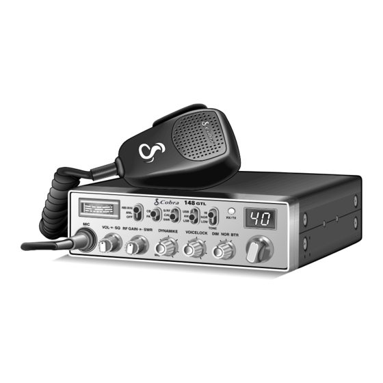
Section IV Operation CONTROLS AND INDICATORS There are thirteen controls and three indicators on the front panel of your COBRA 148GTL. A. CONTROL FUNCTIONS 1. OFF/ON/VOLUME (inner dual concentric). Turn clockwise to apply power to the unit and to set the desired listening level. During normal CB operation, the VOLUME control is used to adjust the output level obtained either at the transceiver speaker or the external speaker, if used. -
Page 7: B.indicator Functions
Section IV Operation (Continued) 10. PA/CB SWITCH. Selects the mode of operation. In the CB position, the PA func- tion is disabled and the unit will transmit and receive on the speaker that is con- nected. In the PA mode, incoming CB transmission will be heard through the PA speaker. -
Page 8: Operating Procedure To Transmit
Section IV Operation (Continued) OPERATING PROCEDURE TO TRANSMIT Select the desired channel of transmission. Set the DYNAMIKE control fully clockwise. If the channel is clear, depress the Push-To-Talk switch on the microphone and speak in a normal voice. RECEIVING SSB SIGNALS There are three types of signals presently used for communications in the Citizens Band: AM, USB, and LSB. -
Page 9: Alternate Microphones And Installation
Section IV Operation (Continued) ALTERNATE MICROPHONES AND INSTALLATION For best results, the user should select a low-impedance dynamic type microphone or a transistorized microphone. Transistorized type microphones have a low output impedance characteristic. The microphones must be provided with a 4-lead cable. The audio conductor and its shielded lead comprise two of the leads. -
Page 10: Section V Maintenance And Adjustment
Section IV Operation (Continued) Fig. 4. Microphone plug pin numbers viewed from rear of pin receptacle. Be sure that the housing and the knurled ring of Fig. 3 are pushed back onto the microphone cable before starting to solder. If the washer is not captive to the pin receptacle body, make sure that it is placed on the threaded portion of the pin receptacle body before soldering. -
Page 11: Section Vi Appendix
Section VI Appendix Citizens Band radio operators have largely adopted the “10-code” for standard questions and answers. Its use permits faster communications and better under- standing in noisy areas. The following table lists some of the more common codes and their meanings. 10 CODE Code Meaning... -
Page 12: Use Channel 9 For Emergency Messages Only
5. Ship prepaid and insured by way of a traceable carrier (to avoid loss in transit) such as United Parcel Service (UPS), Roadway Parcel Service (RPS) or First Class Insured Mail to Cobra Factory Service, Cobra Electronics Corporation, 6500 W. Cortland St., Chicago, IL 60707. Cobra is not responsible for units not received if package has not been properly insured. -
Page 13: Limited Two Year Warranty
LIMITED TWO YEAR WARRANTY COBRA ELECTRONICS CORPORATION warrants that its COBRA CB Radios, and the component parts thereof, will be free of defects in workmanship and materials for period of two (2) years from the date of first consumer purchase. This warranty may be enforced by the first consumer purchaser, provided that the product is uti- lized within the U.S.A. - Page 14 Cobra Electronics Corporation 6500 W. Cortland Street Chicago, IL 60707 PRINTED IN THAILAND ©COBRA ELECTRONICS CORPORATION 1996 480-163-P-...
Need help?
Do you have a question about the Cobra 148 GTL 148 GTL 148 GTL and is the answer not in the manual?
Questions and answers