Table of Contents
Advertisement
Quick Links
Advertisement
Table of Contents

Related Manuals for Dynaudio Sub 6


Summary of Contents for Dynaudio Sub 6
- Page 1 Sub 6 User manual...
- Page 2 Important safety instructions ▪ About this manual ▪ Safety Icons ▪ Signal Words ▪ User Manual Structure ▪ Introduction ▪ Getting to know the Sub 6 ▪ Unpacking ▪ Packaging material ▪ Disposal ▪ Carton contents ▪ Installation ▪ Positioning ▪...
- Page 3 ▪ Firmware Update Procedure...
- Page 4 Sub 6 User manual...
- Page 5 About this operating manual: Signal words The lightning flash with an arrowhead symbol within an equilateral triangle, is intended to alert the user to the presence of uninsulated “dangerous voltage” within the product’s enclosure that may be of sufficient magnitude to constitute a risk of electric shock to persons.
-
Page 6: Important Safety Instructions
Risk of electric shock. Do not open. To reduce the risk of electric shock, do not remove the rear panel and do not expose the apparatus to rain or moisture. No user serviceable parts inside. Refer servicing to qualified personnel. Sub 6 User manual... -
Page 7: About This Manual
User Manual Structure Following this introduction and a section describing the main features of the Sub 6, this manual is divided into three sections in which you can find all the information needed to install and use your Dynaudio Sub 6: ▪... - Page 8 ▪ Configuration and Use: This section describes the functions available through the Sub 6 user interface, how to configure the subwoofer optimally for your system. This section also covers the Sub 6 in use and how to fix any problems that might arise.
- Page 9 Dear music lover Welcome to Dynaudio Sub 6 active DSP subwoofer. The Sub 6 is a very high performance product that rewards thoughtful setup and installation so we suggest that you take a little time to read this manual before you begin.
- Page 10 Getting to know the Sub 6 The Dynaudio Sub 6 is a DSP controlled active subwoofer intended to augment the bass performance of full range speakers in conventional stereo systems. The Sub 6 features a closed box acoustic system and incorporates dual opposed 24cm drivers to minimise mechanical vibration.
-
Page 11: Packaging Material
Note The Sub 6 is heavy and is best unpacked close to its installed location by two people working together. Disposal Disposal of used electrical and electronic equipment (applicable in European countries with separate collection systems for this equipment). -
Page 12: Carton Contents
To remove the grilles simply pull them carefully away from the cabinet. To refit a grille align its pegs with the fittings on the face of the cabinet and gently push the grille home to secure it in place. Always take care not to damage the moving parts of the drive units when removing or replacing grilles. Sub 6 User manual... -
Page 13: Installation
Using a broadband signal, such as pink noise available in the RTA section of the Dynaudio Sound Meter app (available free from the Apple app store), should highlight any impact of room modes in the frequency response. -
Page 14: Positioning Possibilities
Try to locate the position which yields the best compromise between position, volume and even bass response. Note that every time that you reposition the subwoofer (even if it’s over a short distance) you may need Sub 6 User manual... - Page 15 Sub 6 Feet The Sub 6 is supplied with rubber feet and option for spikes. Spike feet are intended to be used on carpeted solid floors. The spikes pierce the carpet to support the subwoofer on the floor below protecting the carpet from damage and providing a stable foundation.
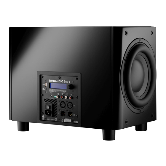
- Page 16 Sub 6 Mains and Signal Connections The Sub 6 is fitted on its rear face with a connection and control panel carrying mains, signal and connection sockets. The panel is illustrated in Diagram 3 and its connection facilities are described in the following paragraphs.
- Page 17 Note If your audio source provides only a mono subwoofer output it can be connected to either Sub 6 left or right input. In this case however the main speakers must be driven from the audio source and not via the Sub 6 outputs.
- Page 18 Connection Scheme 1 ▪ Unbalanced (phono) connection from preamplifier/processor to subwoofer inputs. ▪ Unbalanced connection from subwoofer outputs to power amplifier and passive main speakers. Sub 6 User manual...
- Page 19 Connection Scheme 2 ▪ Balanced (XLR) connection from preamplifier/processor to subwoofer inputs. ▪ Balanced connection from subwoofer outputs to active main speakers. Connection Scheme 3 ▪ Unbalanced (phono) connection from preamplifier/processor to first subwoofer inputs. Installation...
- Page 20 ▪ In order to time-align the subwoofers, the latency of the second subwoofer needs to be accounted for. This is done by adding 86 cm to the left and right distance setting in the first subwoofer. The distance used in the setting should be the Sub 6 User manual...
- Page 21 ▪ The second subwoofer’s input sensitivity should be set to 0 dB. ▪ Balanced connection from second subwoofer outputs to power amplifier and passive main speakers. ▪ The second subwoofer should be distance-aligned as described in Sub 6 DSP Features. ▪ The subwoofers should be level-aligned using their volume setting.
-
Page 22: Connection Scheme
▪ The right and left speaker distances in the right subwoofer should be set the as the right speaker distance described in Sub 6 DSP Features. The Sub Distance should be set as the right subwoofer distance. Subwoofer Control Rotary controller: ▪ Rotate to select. ▪ Press to confirm. Sub 6 User manual... - Page 23 Control and configuration Subwoofer controller Rotary controller: ▪ Rotate to select. ▪ Press to confirm. Control and configuration...
-
Page 24: Configuration And Use
The Sub 6 must be configured appropriately for the audio system and main speakers with which it is to be used. This is achieved via the rotary controller, display and menu based interface on the rear panel. Turn the rotary controller to select configuration parameters and press the control to select options and save any changes. - Page 25 Menu structure: ▪ Volume ▪ Input sensitivity ▪ Preset ▪ Phase ▪ ▪ PEQ Bypass ▪ PEQ 1 ▪ Frequency ▪ Gain ▪ Q ▪ PEQ 2 ▪ Frequency ▪ Gain ▪ Q ▪ PEQ 3 ▪ Frequency ▪ Gain ▪...
-
Page 26: Setting Input Sensitivity
The Sub 6 incorporates low pass filter presets for a range of Dynaudio speaker models. If your Sub 6 is to be used in a system with one of the Dynaudio models listed, select it to automatically configure the Sub 6 low pass filter appropriately. - Page 27 Subwoofer filter frequency set too low F > ▪ L: Level ▪ F: Frequency ▪ Dark grey line: Main speakers ▪ Light grey line: Subwoofer ▪ Brown line: System response A dip in the system response will occur if the filter frequency of the subwoofer is set too low – perhaps with small main speakers that do not have extended bass response.
- Page 28 The equalisation is set “bypassed” by default. Using Parametric Equalisation The digital signal processing power incorporated in Sub 6 enables three bands of parametric equalisation to be applied to the input signal. Parametric equalisation can be viewed as finely targeted tone control that is able to correct specific frequency response anomalies caused by room acoustics.
- Page 29 6 dB of attenuation. Sub 6 Parametric EQ is a powerful tool and it should be used carefully. In the vast majority of circumstances equalisation should be used to attenuate room anomalies rather than not to boost subwoofer bass. If more bass is required always try repositioning the subwoofer first.
- Page 30 Grille Removal and replacement The Sub 6 can be used with its grilles fitted or removed. To remove the grilles simply pull them carefully away from the cabinet. To refit a grille align its pegs with the fittings on the face of the cabinet and gently push the grille home to secure it in place.
- Page 31 Sub 6 Troubleshooting There are various reasons why a subwoofer might not function properly in a system without it being faulty. The following checklist will help solve problems you may encounter. Before consulting your Dynaudio dealer, check this list first.
- Page 32 ▪ Check settings in Bass Management menu of the connected amplifier or receiver. ▪ Carefully and gradually increase the subwoofer volume level on the amplifier or receiver. ▪ Carefully and gradually increase the subwoofer volume level on the subwoofer GAIN control. Sub 6 User manual...
-
Page 33: Updating The Firmware
Updating the Firmware To update the firmware of your Dynaudio subwoofer, proceed as follows. Make a note of the settings in the subwoofer as a Factory Reset may be required after update. Requirements ▪ An empty USB stick formatted to FAT32. A maximum capacity of 8GB is preferable. - Page 34 11. Switch the subwoofer ON. 12. Check the firmware version in the menu info screen. Sub 6 User manual...
- Page 35 Sub 6 Designed and engineered by Dynaudio Labs in Denmark Dynaudio A/S 8660 Skanderborg Denmark dynaudio.com © 2022 Dynaudio A/S All text and image copyrights reserved. Subject to change without notice. Updating the Firmware...
Need help?
Do you have a question about the Sub 6 and is the answer not in the manual?
Questions and answers