Table of Contents
Advertisement
Quick Links
Advertisement
Table of Contents

Subscribe to Our Youtube Channel
Related Manuals for Dynaudio S4-LCRMT


Summary of Contents for Dynaudio S4-LCRMT
- Page 1 Studio Series Installation Manual S4-LCRMT S4-LCR65W...
-
Page 2: Important Safety Instructions
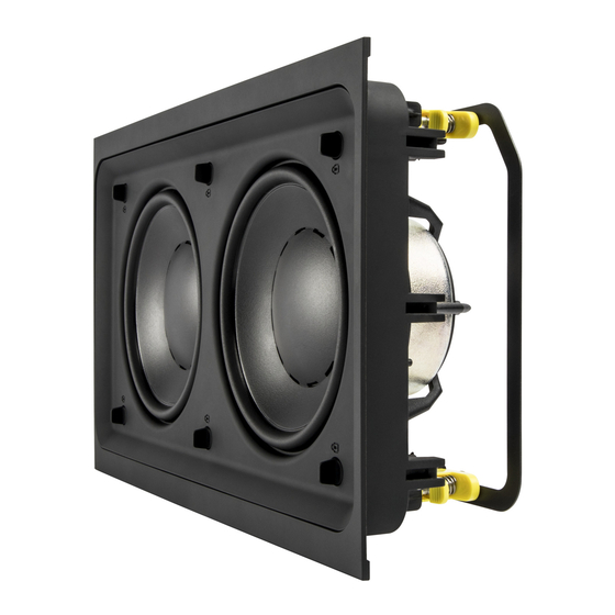
Welcome to the custom install Studio Series and thank you for choosing a Dynaudio Custom Install product. The S4-LCRMT and S4-LCR65W are modular in-wall speakers designed for left, centre and right channel applications in multi-channel audio systems. The S4-LCR Series offers very high quality audio performance while at the same time providing multiple configuration options and incorporating numerous features designed to ease installation. - Page 3 1 x Installation Frame custom install speakers, or if you have not done so for a while, we • S4-LCRMT modules are intended to be installed only in portrait 2 x Frame Flange recommend that you read the appropriate sections of this manual •...
- Page 4 Three typical installation examples are illustrated below. Left and right speakers can be created from an S4-LCRMT module combines with either one, or in larger listening spaces, twin S4- LCR65W modules. Centre channel speakers always require a single S4-LCRMT and twin S4-LCR65W modules.
- Page 5 These dimensions are illustrated in Diagrams 2 and 3 and listed in the table. Diagrams 3A to 3C also illustrate an S4-LCR module with 90.25 mm Frame Flanges fitted and removed, and an S4-LCRMT and S4-LCR65W module ⁄ in) consolidated.
-
Page 6: Speaker Positions
S4-LCR65W modules are installed. Diagram 4 • The mode selection switch on the rear of the S4-LCRMT module should be switched to “1W” if one S4-LCR65W is used (per S4- LCRMT) and switched to “2W” if two are used. Ensure that the mode selection switch position is correct before use. - Page 7 – 4.2 Active Mode Filter S4-LCR65W S4-LCRMT Type Low pass High pass • In active mode, each S4-LCRMT and single or multiple S4- Frequency 300 Hz 500 Hz LCR65W module employed for each channel is connected Slope 12 dB/octave 12 dB/octave separately to a power amplifier channel.
-
Page 8: Speaker Installation
Unit. Strip 15 mm insulation from the cable (if necessary), twist the wire strands and insert the stripped ends into the Note: Diagram 9 illustrates the installation of a S4-LCRMT module. speaker spring terminals. Ensure that the positive conductor S4-LCR65W and multiple module installation is carried out in the is connected to the red speaker terminal and the negative same manner. -
Page 9: Specifications
424 x 230 mm 614 x 230 mm 985 x 230 mm 1319 x 230 mm ⁄ x 9 in ⁄ x 9 in ⁄ x 9 in ⁄ x 9 in ⁄ x 9 in Dynaudio A/S, 8660 Skanderborg, Denmark www.dynaudio.com EN - Item No. 307001017205 Rev K...
Need help?
Do you have a question about the S4-LCRMT and is the answer not in the manual?
Questions and answers