
Related Manuals for GDS Corp GDS-58DXP


Summary of Contents for GDS Corp GDS-58DXP
- Page 1 Operation and Maintenance Manual GDS-58DXP Dual Channel Sample Draw Monitor GDS Corp. 1245 Butler Road League City, TX 77573 409-927-2980 409-927-4180 (Fax) www.gdscorp.com...
- Page 2 GDS-58DXP Operation & Maintenance Manual, Revision 1.0 CAUTION: FOR SAFETY REASONS THIS EQUIPMENT MUST BE OPERATED AND SERVICED BY QUALIFIED PERSONNEL ONLY. READ AND UNDERSTAND INSTRUCTION MANUAL COMPLETELY BEFORE OPERATING OR SERVICING. ATTENTION: POUR DES RAISONS DE SÉCURITÉ, CET ÉQUIPEMENT DOIT ÊTRE UTILISÉ, ENTRETENU ET RÉPARÉ...
-
Page 3: Table Of Contents
GDS-58DXP Operation & Maintenance Manual, Revision 1.00 CONTENTS SAFETY INFORMATION _______________________________________________ 5 PRODUCT OVERVIEW ________________________________________________ 6 HARDWARE _______________________________________________________ 11 INSTALLATION _____________________________________________________ 12 CALIBRATION ______________________________________________________ 17 SETUP AND OPERATION _____________________________________________ 20 MAINTENANCE _____________________________________________________ 25 TROUBLESHOOTING GUIDELINES ______________________________________ 26 SPECIFICATIONS ____________________________________________________ 27... - Page 4 FIGURE 4-3: ANALOG / RELAY MODBUS CONNECTIONS ................14 FIGURE 4-4: RELAY & MODBUS WIRING PATH ..................... 15 FIGURE 4-5: GDS-58DXP WITH OPTIONAL MODBUS WIRING JUNCTION BOX (MBJB) ......... 16 FIGURE 6-1: GDS-58DXP GAS DETECTOR DISPLAY ..................20 FIGURE 9-1: TOXIC SENSOR CHARACTERISTICS & RECOMMENDED WARM-UP TIME ......... 28 FIGURE 9-2: GDS-IR SENSOR CHARACTERISTICS &...
-
Page 5: Safety Information
GDS-58DXP is suitable for the intended use. ▪ The GDS-58DXP is designed and constructed to measure the level of certain gases in ambient air. Accuracy in atmospheres containing steam or inert gases cannot be guaranteed. -
Page 6: Product Overview
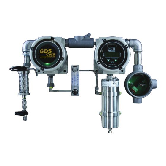
The GDS-58DXP consists of a gas detector coupled with an integrated pump / flow switch and wiring junction box. The Run / Cal valve selects between the sample input and local calibration gas input. The Visual Flow Indicator shows GREEN if flow is OK, and RED if flow is blocked or the pump fails. -
Page 7: Figure 2-2: Gds-58Dxp Flow Diagram
Figure 2-2: GDS-58DXP Flow Diagram GDS-58DXP SENSOR TECHNOLOGY For toxic gases the GDS-58DXP supports a range of electrochemical (“echem”) sensors for toxic gases and oxygen levels. These sensors use chemical reactions to sense the presence of gases such as hydrogen sulfide, sulfur dioxide and many others. -
Page 8: Figure 2-3: Gds-58Dxp Ambient Air Sampling
The sample pump used on the GDS-58DXP is capable of lifting liquid water to a height of 15 ft / 5m, and if the end of the sample line is placed in liquid water, the pump will draw water through the inlet filter, flame arrestors, sample pump, flow switch and flow meter and sensor flow cell, resulting in damage to the components. -
Page 9: Figure 2-4: Filter Option #1
GDS-58DXP Operation & Maintenance Manual, Revision 1.00 In addition to end-of-line filters & probes, the GDS-58DXP offers three choices for inlet filters that are directly integrated into the unit. These filters are mounted on the left side, in-between the flame arrestor and Run/Cal valve. -
Page 10: Figure 2-6: Filter Option #3
Using a GDS-58DXP with a #20-0141 Duct Sample Kit simplifies installation, maintenance and calibration and samples a larger cross-section of the duct stream. -
Page 11: Hardware
GDS-58DXP Operation & Maintenance Manual, Revision 1.00 3 HARDWARE The GDS-58DXP consists of two NEMA 7 explosion-proof enclosures that contain the sample pump and flow switch (left side) and GASMAX DSX gas monitor, sensor, and flow cell (right side). Gas enters the left side enclosure via explosion proof flame arrestors, passes through the flow meter and into the sensor. -
Page 12: Installation
GDS-58DXP Operation & Maintenance Manual, Revision 1.0 4 INSTALLATION SELECTING A LOCATION As compared to a fixed-point gas detector, the GDS-58DXP sample draw system provides a good deal of flexibility when choosing a mounting location. Consider the following when considering where to install the GDS-58DXP: •... -
Page 13: Figure 4-1: Power And Analog Signal Wiring Path
To access signal and power connections, remove the cover on the wiring junction box mounted on the right side of the GDS-58DXP. Power, ground (common) and signal outputs are shown in figure 5-4 below. Connect power to TB1 pin 1 and ground to TB1 pin 6. Additional+24V (TB1 pin 2) and Common (TB1 pin 5) connections are available for local strobes or horns. -
Page 14: Figure 4-2: Gds-58Dxp Power And Signal Wiring
GDS-58DXP Operation & Maintenance Manual, Revision 1.0 TB2 – 1: +24VDC TB2 – 2: +24VDC TB2 – 3: 4-20mA Ch1 Out TB2 – 4: 4-20mA Ch2 Out TB2 – 5: Common TB2 – 6: Common Figure 4-2: GDS-58DXP Power and Signal Wiring... -
Page 15: Figure 4-4: Relay & Modbus Wiring Path
4000 feet without a repeater. For MODBUS data signals, GDS Corp recommends 20GA to 24GA shielded cable. Daisy-chain power distribution may require larger gauge wire since it is critical that the supply voltage for the GDS-58DXP at the far end of the string not fall below 22VDC during power-up. -
Page 16: Figure 4-5: Gds-58Dxp With Optional Modbus Wiring Junction Box (Mbjb)
OPTIONAL MODBUS WIRING JUNCTION BOX [MJBJ] If the GDS-58DXP is to be used in a MODBUS daisy chain configuration, GDS Corp recommends the addition of the MODBUS Wiring Junction Box (see Fig. 4-3). This option minimizes the need to access... -
Page 17: Calibration
GDS-58DXP Operation & Maintenance Manual, Revision 1.00 5 CALIBRATION Calibration is critically important to ensure correct operation of the GDS-58DXP. The built-in CAL MODE function is designed to make calibration quick, easy and error free; a successful ZERO and SPAN calibration requires only four keystrokes. - Page 18 GDS-58DXP Operation & Maintenance Manual, Revision 1.0 CALIBRATION PROCEDURE Before beginning calibration, make sure you have the following items: A cylinder of calibration gas, fixed flow regulator and a length of flexible tubing. A cylinder of ‘zero air’ may be necessary if the absence of target gas cannot be confirmed in the sample area.
- Page 19 GDS-58DXP Operation & Maintenance Manual, Revision 1.00 Wait for the ZERO CAL COMPLETE screen to ZERO CAL appear. The system will return to the Calibration 1. COMPLETE Menu. DONE, STOPPING Remove the cylinder or ZERO AIR and attach a cylinder of SPAN GAS to the Run/Cal valve.
-
Page 20: Setup And Operation
UNDERSTANDING THE USER INTERFACE Once installed, apply power to the GDS-58DXP and verify that the LCD display is active. There are three magnetic switches on the face of the GDS-58DXP, arranged to the left, right and below the display. The left-side switch is “DOWN”... - Page 21 PROGRAMMING ALARM LEVELS The GDS-58DXP has three alarm levels that activate each of the three alarm relays. Each alarm can be set to a different level and can be programmed to trigger when the input goes ABOVE the alarm value (HIGH) or BELOW the alarm value (LOW).
- Page 22 GDS-58DXP Operation & Maintenance Manual, Revision 1.0 With the cursor as shown, use the UP and DOWN keys to THRESHOLD [VALUE] set the alarm level. When complete, press ENTER. ACTIVE MODE HIGH/LOW PREVIOUS MENU Press the DOWN key to select ACTIVE MODE. Use the UP or THRESHOLD [VALUE] DOWN keys to select the alarm mode.
- Page 23 GDS-58DXP Operation & Maintenance Manual, Revision 1.00 PROGRAMMING RELAYS Each LOW, MID and HIGH alarm setting is logically connected to the LOW, MID and HIGH alarm relays. When operating in dual channel mode, the relay output is a LOGICAL OR from each of the two channels.
- Page 24 3) Install the sample inlet and exhaust tubing 4) Set the Run/Cal valve to the RUN position and apply power to the GDS-58DXP. Verify that the flow meter shows ~0.5 liters / minute or more. Allow the unit to warm up for the recommended time.
-
Page 25: Maintenance
The flow switch is sealed and does not have any user-serviceable parts. In the event that water or other liquid enters the GDS-58DXP, the flow meter, flow switch and flame arrestors may need to be replaced or cleaned thoroughly. The flame arrestors can be cleaned and dried using compressed air or heat. -
Page 26: Troubleshooting Guidelines
Sensor reading during span calibration too low – sensor may be defective. RECEIVING DEVICE (4-20mA) AND GDS-58DXP DISPLAYED VALUES DON’T MATCH • Check that zero and full-scale range values match between GDS-58DXP and receiving device (controller). • Check for high impedance shorts to ground on 4-20mA wiring. -
Page 27: Specifications
GDS-58DXP Operation & Maintenance Manual, Revision 1.00 9 SPECIFICATIONS Model GDS-58DXP Sample Draw System Power Input 24VDC ± 5% at < 10 watts (Toxic sensor) 24VDC ± 5% at < 15 watts (GDS-IR sensor) Display LCD with engineering units display... -
Page 28: Figure 9-1: Toxic Sensor Characteristics & Recommended Warm-Up Time
GDS-58DXP Operation & Maintenance Manual, Revision 1.0 Sensor Type Min Range Max Range Temp Range Warm-Up 2 to 4 hours Oxygen 0-25% v/v 0-25% v/v 0°C to + 55°C 2 to 4 hours Carbon Monoxide 0-100 ppm 0-9999 ppm 0°C to + 50°C... -
Page 29: Figure 9-2: Gds-Ir Sensor Characteristics & Recommended Warm-Up Time
GDS-58DXP Operation & Maintenance Manual, Revision 1.00 Sensor Type Range Temp Range Warm-Up Acetylene 4 to 8 hours 0-100% LEL 0°C to + 55°C Methane 4 to 8 hours 0-100% LEL 0°C to + 55°C Propane 4 to 8 hours 0-100% LEL 0°C to + 55°C... -
Page 30: Modbus Registers
GDS-58DXP Operation & Maintenance Manual, Revision 1.0 10 MODBUS REGISTERS The GDS-58DXP features a set of user-accessible MODBUS registers that allow a remote MODBUS master device to SERIAL PORT SETTINGS Parameter Setting Notes Baud Rate 9600 baud Fixed value Start Bit... -
Page 31: Spare Parts
Pump mounting bracket 20-0193 Junction Box PCB Indicator PCB 1200-0037 Sensor Head Assembly: Run/Cal Valve 10-0247 GDS-IR See Fig. 3-3 for List 1200-0056 Flowmeter 10-0271 Flow Cell for GDS-IR Figure 11-1: GDS-58DXP Assembly with Toxic Sensor (Spare Parts) Page 31... -
Page 32: Figure 11-2: Gds-58Dxp Assembly With Gds-Ir Sensor (Spare Parts)
1200-0160 Pump mounting bracket 20-0193 Junction Box PCB Indicator PCB 1200-0037 Run/Cal Valve 1200-0056 Flowmeter Sensor Head Assembly: GDS-IR See Fig. 3-3 for List 10-0271 Flow Cell for GDS-IR Figure 11-2: GDS-58DXP Assembly with GDS-IR Sensor (Spare Parts) Page 32... -
Page 33: Drawings And Dimensions
GDS-58DXP Operation & Maintenance Manual, Revision 1.00 12 DRAWINGS AND DIMENSIONS GDS-58DXP DIMENSIONS (SINGLE TOXIC SENSOR) 20” 5.0” 5.0” ¼” Compression 10.5” ¼” Compression Figure 12-1: GDS-58DXP Dimensions (Single Toxic Sensor) Page 33... -
Page 34: Figure 12-2: Gds-58Dxp Dimensions (Gds-Ir Sensor)
GDS-58DXP Operation & Maintenance Manual, Revision 1.0 GDS-58DXP DIMENSIONS (GDS-IR SENSOR) 20” 5.0” 5.0” ¼” Compression 14” ¼” Compression Figure 12-2: GDS-58DXP Dimensions (GDS-IR Sensor) Page 34... -
Page 35: Figure 12-3: Gds-58Dxp Dimensions (Stainless Steel Plate, 1 Sensor)
GDS-58DXP Operation & Maintenance Manual, Revision 1.00 GDS-58DXP MOUNTING PLATE DIMENSIONS (EITHER SENSOR TYPE) 21” ¼” Compression 21” 19.25” .50” DIA (4x) ¼” Compression 19.25” Figure 12-3: GDS-58DXP Dimensions (Stainless Steel Plate, 1 Sensor) Page 35... -
Page 36: Figure 12-4: Gds-58Dxp Enclosure Dimensions (Non-Metallic)
GDS-58DXP Operation & Maintenance Manual, Revision 1.0 GDS-58DXP DIMENSIONS (Non-Metallic Enclosure) 25.6” 10.4” 25.6” Figure 12-4: GDS-58DXP Enclosure Dimensions (Non-Metallic) Page 36... -
Page 37: Sample Draw Duct Assembly 20-0141
GDS-58DXP Operation & Maintenance Manual, Revision 1.00 13 SAMPLE DRAW DUCT ASSEMBLY 20-0141 Figure 13-1: Sample Draw Duct Assembly Figure 13-2: Sample Draw Duct Assembly Hole Mounting Pattern NOTE: APPLY GASKET SEAL ON FACE OF PLATE WHEN INSTALLING SAMPLE DRAW DUCT ASSEMBLY... - Page 38 GDS Corp. 1245 Butler Road League City, TX 77573 409-927-2980 409-927-4180 (Fax) www.gdscorp.com...
Need help?
Do you have a question about the GDS-58DXP and is the answer not in the manual?
Questions and answers