
Related Manuals for GDS Corp GDS-68XP


Summary of Contents for GDS Corp GDS-68XP
- Page 1 Operation and Maintenance Manual GDS-68XP Process Monitor for Low O Applications GDS Corp. 2513 Hwy 646 Santa Fe, Texas 77510 409-927-2980 409-927-4180 (Fax) ww.gdscorp.com...
- Page 2 GDS-68XP Operation & Maintenance Manual, Revision 3.4 CAUTION: FOR SAFETY REASONS THIS EQUIPMENT MUST BE OPERATED AND SERVICED BY QUALIFIED PERSONNEL ONLY. READ AND UNDERSTAND INSTRUCTION MANUAL COMPLETELY BEFORE OPERATING OR SERVICING. ATTENTION: POUR DES RAISONS DE SÉCURITÉ, CET ÉQUIPEMENT DOIT ÊTRE UTILISÉ, ENTRETENU ET RÉPARÉ...
-
Page 3: Table Of Contents
GDS-68XP Operation & Maintenance Manual, Revision 3.4 CONTENTS SAFETY INFORMATION _______________________________________________ 8 GENERAL INFORMATION ______________________________________________ 9 Introduction ________________________________________________________________ 9 Explosion Proof Installation ____________________________________________________ 9 Intrinsically Safe Installation ___________________________________________________ 9 SPECIFICATIONS ____________________________________________________ 10 OPERATION _______________________________________________________ 12 Overview _________________________________________________________________ 12 Sample Draw Configuration ___________________________________________________ 14... - Page 4 GDS-68XP Operation & Maintenance Manual, Revision 3.4 INITIAL SETUP______________________________________________________ 24 Overview _________________________________________________________________ 24 Sequencer Controls and Indicators _____________________________________________ 24 SEQUENCE ______________________________________________________________________ 24 Bypass _________________________________________________________________________ 25 Run ____________________________________________________________________________ 25 L1 and L2 _______________________________________________________________________ 25 GASMAX Controls and DIsplay ________________________________________________ 26 RAW SENSOR ____________________________________________________________________ 26...
- Page 5 Fault Indication on OUTPUT Channel (CH2) ______________________________________ 50 Fault Indication on raw Sensor Channel (CH1) ____________________________________ 50 Sensor Fails Calibration ______________________________________________________ 50 GDS-68XP and Receiving Device Displayed Values Don’t Match ______________________ 50 Controller MODBUS Data Incorrect _____________________________________________ 51 Controller Showing MODBUS COMM ERROR _____________________________________ 51...
- Page 6 FIGURE 9-6: SYSTEM SETTINGS MENU TREE .................... 40 FIGURE 9-7: DIAGNOSTICS MENU TREE ....................41 FIGURE 12-1: GDS-68XP SAMPLE DRAW COALESCING FILTER (SPARE PARTS) ........... 52 FIGURE 12-2: GDS-68XP LOW PRESSURE COALESCING FILTER (SPARE PARTS) .......... 53 FIGURE 12-3: GDS-68XP HIGH PRESSURE COALESCING FILTER (SPARE PARTS).......... 54 FIGURE 12-4: GDS-68XP HIGH PRESSURE BYPASS FILTER (SPARE PARTS) ..........
- Page 7 GDS-68XP Operation & Maintenance Manual, Revision 3.4 FIGURE 12-5: GDS-68XP SENSOR HEAD EXPLODED VIEW ................. 56 FIGURE 13-1: GDS-68XP DIMENSIONS (NEMA 4X ENCLOSURE) ..............57 FIGURE 14-1: GDS-68XP WIRING DIAGRAM ..................... 58 Page 7...
-
Page 8: Safety Information
Installation in any hazardous area must comply with all applicable restrictions, requirements and guidelines for said hazardous areas. It is the end user customer’s final decision to ensure that the GDS-68XP is suitable for the intended use. -
Page 9: General Information
The GDS-68XP provides a safe and reliable way to measure the level of hydrogen sulfide, mercaptan, THT and other gases in a process stream that contains low levels of oxygen. The GDS-68XP uses a programmed sequencer to alternatively apply sample and purge air to a highly sensitive and reliable electrochemical sensor. -
Page 10: Specifications
50°F and is not user-adjustable. Temperature -20°C to +55°C (inert) In cold weather, GDS Corp recommends turning on the AC heater (if installed) for several hours before applying DC power Memory On-board non-volatile memory retains all user settings Materials Instrument housings: Aluminum Tubing &... -
Page 11: Figure 3-1: Toxic Sensor Characteristics
GDS-68XP Operation & Maintenance Manual, Revision 3.4 Type Target Gas Min Span Max Span Temp Range Warm-Up Hydrogen Sulfide 0-10 ppm 0-5000 ppm 0°C to + 50°C 2 to 4 hours Mercaptan 0-15 ppm 0-30 ppm 0°C to + 40°C... -
Page 12: Operation
As electrochemical sensors require oxygen to operate, the GDS-68XP alternatively exposes the sensor to the process flow and then purges the sensor with ambient air to maintain the sensor in a sensitive, oxygenated state. -
Page 13: Figure 4-2: Gds-68Xp Sample Timing
GDS-68XP enters Recovery mode where purge air flows into the sample flow cell. Once the sensor output drops below 10% of scale, the GDS-68XP transfers the stored reading to the 4-20mA and MODBUS output. In the event that an overrange, loss of flow, peak-find algorithm fault, non- return-to-zero fault, sensor fault or calibration fault occurred during the sequence, a specific fault indication value will be output in place of the measured value. -
Page 14: Sample Draw Configuration
GDS-68XP Operation & Maintenance Manual, Revision 3.4 SAMPLE DRAW CONFIGURATION In addition to low and high positive pressure versions, the GDS-68XP can be configured to draw a sample from ambient pressure sources. In this configuration the pump operates continuously to pull from both purge air and sample sources (See Fig. -
Page 15: Installation
Make sure there is sufficient clearance below and to the left side of the GDS-68XP to allow room for power & signal cables, purge air, sample, filter bypass (if installed), filter drain and sample exhaust tubing. -
Page 16: Power & Signal Connections
J1-2 (See Fig. 5-2). ON-DEMAND SEQUENCE INPUT If the “on-demand’ sequencer mode is selected the GDS-68XP will enter a hold mode until an external contact closure between J6-1 and J6-2 occurs. This causes the GDS-68XP to perform a single sample sequence. -
Page 17: Relay Connections (Optional)
ARCING WHICH SHORTENS LIFE AND MAY INTERFERE WITH SENSOR DATA. MODBUS CONNECTIONS (OPTIONAL) The dual optional GDS-68XP MODBUS RTU interface allows remote controllers or PLCs to monitor most aspects of operation, including real-time data, range and alarm setpoints and alarm and fault status bits. -
Page 18: Figure 5-4: Modbus Wiring Junction Box
24GA twisted shielded cable. Daisy-chain power distribution “B” may require larger gauge wire since it is critical that the supply voltage for the GDS-68XP at the far end of the string not fall below 22VDC during power-up. +24 GND A Note that while the GDS-68XP has two sets of wiring terminals for MODBUS “A”... -
Page 19: Ac Heater (Optional)
GDS Corp recommends placing the Purge Air inlet some distance from the GDS-68XP, in a location that is free from background gas and protected from heavy rains, water spray and snow or ice. Included with the unit is a ¼” screen fitting that must be placed over the open end of the purge air inlet to keep dust, dirt, water droplets and insects from entering the tubing and being drawn into the purge air pump. -
Page 20: Sample Inlet
SAMPLE INLET The length of time it takes gas to flow from the sample source to the GDS-68XP inlet should not exceed 30 seconds to ensure that “fresh” sample is available at the beginning of each measurement cycle. For ¼” OD stainless steel tubing and sample flow rates of approximately 0.5 liters per minute, the maximum length... -
Page 21: Filter Drain & Filter Bypass
NOTE: LEAVING THE FILTER DRAIN VALVE ‘CRACKED’ OPEN WILL ALLOW SAMPLE GAS TO FLOW FROM THE PICKUP POINT TO THE GDS-68XP ON A CONTINUOUS BASIS, ENSURING THAT FRESH SAMPLE IS ALWAYS AVAILABLE AT THE BEGINNING OF EACH NEW SAMPLE SEQUENCE. -
Page 22: Sample Exhaust
IMPORTANT: DO NOT RESTRICT SAMPLE EXHAUST OUTLET. PRESSURE IN THE SAMPLE FLOW CELL MAY DAMAGE THE SENSOR AND WILL RESULT IN INCORRECT READINGS. IMPORTANT: WHEN INSTALLING THE GDS-68XP OUTDOORS, MAKE SURE SAMPLE EXHAUST IS PROTECTED BY A SCREEN OR FILTER TO KEEP INSECTS FROM ENTERING THE EXHAUST PORT AND NESTING IN THE SENSOR FLOW CELL. -
Page 23: Installation Summary: Do's And Don'ts
Select an installation location that protects the unit from shock, vibration and damage • Always mount the GDS-68XP vertically to ensure proper operation of the low flow switch • Make sure the power wiring is appropriate for the DC load and distance •... -
Page 24: Initial Setup
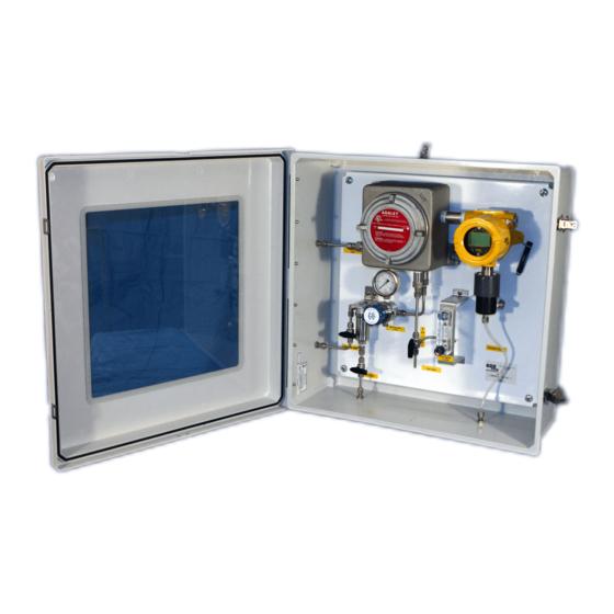
“VALVE” “PUMP” Figure 6-1: GDS-68XP User Interface The GDS-68XP sequencer monitors the output of the GASMAX raw sensor channel and flow switch and controls the operation of the purge air pump and 3-way valve. SEQUENCE switch setting determine the length of time between each sample cycle. There are seven preset sample times and one ‘on-demand’... -
Page 25: Bypass
GDS-68XP Operation & Maintenance Manual, Revision 3.4 SEQUENCE Sequence Purge / Hold Total Cycle Time Switch (Approximate) Time Time On-Demand Sequence 1 hour 12-15 min 40 min 1 hour 12-15 min 105 min 2 hours 12-15 min 165 min 3 hours... -
Page 26: Gasmax Controls And Display
Chapter 6. NEXT Pressing the key momentarily causes the GDS-68XP display to sequence display screens between DUAL DISPLAY, RAW SENSOR TREND, PPM OUTPUT TREND, RAW SENSOR, and PPM OUTPUT. Figure 6-4: GDS-68XP GASMAX Display Sequence RAW SENSOR displays the calibrated gas value being read by the sensor at any moment. -
Page 27: Gds-68Xp Startup Procedure
DCS OR PLC OUTPUT TO 4MA / 20MA AND VERIFY READING ON RECEIVING DEVICE GDS-68XP COMPLETES FIRST SEQUENCE AND ENTERS PURGE / HOLD MODE: OUTPUT = “FLOW FAULT”, L2 (GREEN) FLASHING OPEN SAMPLE INLET VALVE VERIFY PRESSURE ON PRESSURE GAUGE DO NOT RE-ADJUST FLOW METER VALVE PRESS “BYPASS”... -
Page 28: Calibration
In all cases, the GDS-68XP should be calibrated at least once every three months. Furthermore, during the initial six months of operation, the GDS-68XP should be checked more often to verify that the sensor is operating properly and that some component of the sample gas mixture has not damaged the sensor or change the sensor’s response to the target gas compound. -
Page 29: Calibration Procedure (Cal Port Sample)
GDS-68XP Operation & Maintenance Manual, Revision 3.4 CALIBRATION PROCEDURE (CAL PORT SAMPLE) Calibration using the built-in calibration port is the fastest and most convenient method. When the GASMAX enters CAL MODE, the purge air pump automatically turns on to provide zero air flow from ambient air;... -
Page 30: Calibration Procedure (Inlet Port Sample)
GDS-68XP Operation & Maintenance Manual, Revision 3.4 CALIBRATION PROCEDURE (INLET PORT SAMPLE) Calibration using the Inlet Port will more closely approximate the actual sample gas flow path through the filter, regulator and sequencer valve. Connect the calibration gas cylinder and regulator... -
Page 31: Calibration Procedure (Stream Sample)
If the gas level is known, the following procedure can be used to adjust the output of the GDS-68XP to match the current level of target gas. CALIBRATION PROCEDURE – STREAM SAMPLE... -
Page 32: Operation And Maintenance
Always check the flow meter for the presence of moisture. In the event that moisture or liquid is drawn in the GDS-68XP, the entire unit should be disassembled and cleaned. In some cases the flow meter or flow switch may need to be replaced. If liquid is drawn into the GDS-68XP, always inspect the sensor for signs of damage. -
Page 33: Fault And Overrange Conditions
– If the sensor output higher than 10% of scale, or lower than -10% of scale when a sequence starts the GDS-68XP will indicate a “calibration fault”. The GDS-68XP will also indicate a “calibration fault” if the GASMAX is placed in Cal Mode at any time during a sample sequence. -
Page 34: Sensor Replacement
GDS-68XP Operation & Maintenance Manual, Revision 3.4 SENSOR REPLACEMENT If a sensor shows FAULT, does not respond to gas or can no longer be calibrated, it should be replaced. Use type 10-98XX-Ryyyy sensors, where the XX is gas type (Fig. 3-1) and yyyy is range (25 = “0025”). -
Page 35: User Menus
The GASMAX CX gas monitor used in the GDS-68XP has a menu-driven user interface that allows the operator to review and adjust a wide range of settings. In the GDS-68XP, channel 1 of the GASMAX CX measures the “raw sensor” gas level and channel 2 provides continuous display, output and alarming on the stored value retained in the sequencer memory. -
Page 36: Alarm Outputs Menu
GDS-68XP Operation & Maintenance Manual, Revision 3.4 ALARM OUTPUTS MENU The Alarm Outputs Menu controls the four optional alarm relays (if installed). These setting include relay programming, acknowledge, failsafe mode and specific input override options. NOTE: The Alarm / Modbus board containing the 3x alarm relays and 1x fault relay is optional on the GDS-68XP. -
Page 37: Channel Settings Menu
GDS-68XP Operation & Maintenance Manual, Revision 3.4 CHANNEL SETTINGS MENU The Channel Settings Menu allows the user to adjust individual channel or sensor-specific features. Data in the Channel Settings Menu is uploaded from Smart Sensors, and written back to any local Smart Sensor if changed in the menu. -
Page 38: Figure 9-4: Channel Settings Menu Tree (2)
GDS-68XP Operation & Maintenance Manual, Revision 3.4 Temperature Compensation compensates for changes in sensor output (gain) and zero value (offset) as sensor temperature changes. Individual values for gain and offset can be entered for eleven points ranging from Temp. Comp. -
Page 39: Comm Settings Menu
GDS-68XP Operation & Maintenance Manual, Revision 3.4 COMM SETTINGS MENU The Comm Settings Menu allows the user to configure the Ethernet interface, MODBUS/TCP slave and two optional RS-485 serial interfaces. Comm Settings Comm Settings Comm Settings Comm Settings Comm X Menu (both comm port setting menus are identical) COMM 1 Settings →... -
Page 40: System Settings Menu
GDS-68XP Operation & Maintenance Manual, Revision 3.4 SYSTEM SETTINGS MENU The Comm Settings Menu allows the user to configure the Ethernet interface, MODBUS/TCP slave and two optional RS-485 serial interfaces. System System System System Configure Menu Version v1.00 Date & Time – Sets the system date and time. Used for display and event Configure →... -
Page 41: Diagnostics Menu
GDS-68XP Operation & Maintenance Manual, Revision 3.4 DIAGNOSTICS MENU The Diagnostics page provides tools for use during setup or testing. Tests for optional features are not available if the feature is not installed. Diagnostics Relays → Analog Inputs → Analog Outputs →... -
Page 42: Modbus Registers
GDS-68XP Operation & Maintenance Manual, Revision 3.4 10 MODBUS REGISTERS The GDS-68XP features a full complement of user-accessible MODBUS registers that can provide a complete snapshot of the gas detector configuration. This includes all real-time data, preset zero, span and calibration values and user-programmable text. - Page 43 GDS-68XP Operation & Maintenance Manual, Revision 3.4 SR 2 State 32021 True if relay #2 active SR 3 State 32022 True if relay #3 active FR State 32023 True if fault relay active Warmup 32025 True if unit in warm-up...
- Page 44 GDS-68XP Operation & Maintenance Manual, Revision 3.4 Ch 2 I/O Error 33056 True if input/output error Ch 2 Cal Flag 33057 True if calibration in progress Ch 2 Marker Flag 33058 True if marker active Ch 2 Linearize 33059 True if linearization table active...
- Page 45 GDS-68XP Operation & Maintenance Manual, Revision 3.4 Gateway IP 40074 Ethernet port: xxx.xxx.xxx.xxx Modbus TCP Byte Order 40080 MODBUS/TCP function Modbus TCP Timeout 40081 MODBUS/TCP timeout (mSec) Modbus TCP Poll Delay 40082 MODBUS/TCP poll delay (mSec) Save Config 40095 Write command to save local config...
- Page 46 GDS-68XP Operation & Maintenance Manual, Revision 3.4 Ch 1 Preamp gain 40433 Contact factory Ch 2 Preamp gain 40434 Contact factory Ch 1 Cal Zero 42001 Modbus 32 bit IEEE 754 Floating Pt Ch 1 Cal Span 42003 Modbus 32 bit IEEE 754 Floating Pt...
- Page 47 GDS-68XP Operation & Maintenance Manual, Revision 3.4 Ch 1 Data From 43031 Selection Ch 1 Min Raw 43032 Binary (800) Ch 1 Max Raw 43033 Binary (4000) Ch 1 Remote ID 43034 Binary Ch 1 Interface 43035 Binary Ch 1 Byte Order...
- Page 48 GDS-68XP Operation & Maintenance Manual, Revision 3.4 Ch 2 Alarm 1 Latch 43201 False = NO, True = YES Ch 2 Alarm 1 Trip 43202 False = HIGH, True = LOW Ch 2 Alarm 1 On Delay 43203 Activation delay in seconds...
- Page 49 GDS-68XP Operation & Maintenance Manual, Revision 3.4 Ch 2 Balance 43295 Binary Ch 2 Heater Enable 43296 False = NO, True = YES Ch 2 Heater Setpoint 43297 Modbus 32 bit IEEE 754 Floating Pt Ch 2 Temp Comp -40...
-
Page 50: Troubleshooting Guidelines
PREAMP GAIN. GDS-68XP AND RECEIVING DEVICE DISPLAYED VALUES DON’T MATCH Check that zero and full scale range values match between GDS-68XP and receiving device • (controller). Use DIAGNOSTICS menu to force the OUTPUT channel (Ch2) to 12mA and verify half-scale reading on remote controller. -
Page 51: Controller Modbus Data Incorrect
Verify that controller MIN and MAX count settings are correct. MIN counts should be “800” • which corresponds to 4mA and MAX counts should be “4000” which corresponds to 20 mA. Verify that the GDS-68XP MODBUS address matches the address programmed into the • controller’s channel configuration. -
Page 52: Spare Parts
3-way valve 1200-0034 Flame Arrestors (3) Display: 10-0387 I/O Board: 10-0390 Optional Relays & MB 10-0388 Sensor Head: 10-0247 Flow Cell: 10-0205 Filter 1200-0056 Flow Meter 10-0205 Filter Element 10-xxxx Figure 12-1: GDS-68XP Sample Draw Coalescing Filter (Spare Parts) Page 52... -
Page 53: Figure 12-2: Gds-68Xp Low Pressure Coalescing Filter (Spare Parts)
Flame Arrestors (3) Display: 10-0387 I/O Board: 10-0390 Optional Relays & MB 10-0388 Sensor Head: 10-0247 Flow Cell: 10-0205 1200-0056 Filter 1200-0037 Flow Meter Run/Cal Valve 10-0205 Filter Element 10-xxxx Figure 12-2: GDS-68XP Low Pressure Coalescing Filter (Spare Parts) Page 53... -
Page 54: Figure 12-3: Gds-68Xp High Pressure Coalescing Filter (Spare Parts)
Flame Arrestors (3) Display: 10-0387 I/O Board: 10-0390 Optional Relays & MB 10-0388 Sensor Head: 10-0247 Flow Cell: 10-0205 Filter 1200-0037 1200-0056 Run/Cal Valve Flow Meter 10-0205 Filter Element 10-xxxx Figure 12-3: GDS-68XP High Pressure Coalescing Filter (Spare Parts) Page 54... -
Page 55: Figure 12-4: Gds-68Xp High Pressure Bypass Filter (Spare Parts)
Flame Arrestors (3) Display: 10-0387 I/O Board: 10-0390 Optional Relays & MB 10-0388 Sensor Head: 10-0247 Flow Cell: 10-0205 Filter 1200-0037 1200-0056 Run/Cal Valve Flow Meter 10-0205 Filter Element 10-xxxx Figure 12-4: GDS-68XP High Pressure Bypass Filter (Spare Parts) Page 55... - Page 56 GDS-68XP Operation & Maintenance Manual, Revision 3.4 Sensor Head Assembly (10-0247) Sensor Head Base Sensor: 10-98XX - RYYYY Sensor Head Cover Figure 12-5: GDS-68XP Sensor Head Exploded View Page 56...
-
Page 57: Drawings And Dimensions
GDS-68XP Operation & Maintenance Manual, Revision 3.4 13 DRAWINGS AND DIMENSIONS 25.6” 10.4” 25.6” Figure 13-1: GDS-68XP Dimensions (NEMA 4X Enclosure) Page 57... -
Page 58: Wiring Diagrams
GDS-68XP Operation & Maintenance Manual, Revision 3.4 14 WIRING DIAGRAMS Electrical GASMAX I/O BOARD “B” to GASMAX 4-20 In SEQUENCER PCB “A” from GASMAX CH1 Out +24VDC “C” from GASMAX CH2 Out 14 Pin Ribbon Cable 14 Pin Ribbon Cable... -
Page 59: Gasmax Cx Gds-68Xp Factory Default Setup
GDS-68XP Operation & Maintenance Manual, Revision 3.4 15 GASMAX CX GDS-68XP FACTORY DEFAULT SETUP Values shown are for units configured for a range of 0-50 mg/m3. For alternative ranges, modify the SPAN, ENGINEERING UNITS, CAL SPAN VALUE and ALARM LEVEL settings as necessary. - Page 60 GDS-68XP Operation & Maintenance Manual, Revision 3.4 Trip On High On Delay Off Delay Deadband Alarm 2 Setpoint 50.0 No alarms from channel 1 Latching Trip On High On Delay Off Delay Deadband Alarm 3 Enabled? No alarms from channel 1 Setpoint 50.0...
- Page 61 GDS-68XP Operation & Maintenance Manual, Revision 3.4 Gain / Offset 1.00 / 0.00 Gain / Offset 1.00 / 0.00 Gain / Offset 1.00 / 0.00 Gain / Offset 1.00 / 0.00 Gain / Offset 1.00 / 0.00 Gain / Offset 1.00 / 0.00...
- Page 62 GDS-68XP Operation & Maintenance Manual, Revision 3.4 On Delay Off Delay Deadband Alarm 3 Enabled? Setpoint 60% of scale Latching Trip On High On Delay Off Delay Deadband Fault Alarm Setpoint -10% of scale Data From Sensor Type AI 4-20mA...
- Page 63 GDS-68XP Operation & Maintenance Manual, Revision 3.4 Gain / Offset 1.00 / 0.00 Configure Tag Name GDS-68XP Eunits Mg/m3 Zero Span Decimal Points Channel On? Deadband In-Cal mA Comm Settings Menu Comm 1 Type MB Slave Programmed by user Baud Rate...
- Page 64 GDS-68XP Operation & Maintenance Manual, Revision 3.4 Network Settings DHCP Enabled? Programmed by user Hostname GDS-68XP IP Address Netmask Gateway Security Menu Lock Code **** Factory default MB/Web Code 1234 Contact Info Default System Menu Version Configure System name GDS68XP...
-
Page 65: Sequencer Settings (Dip Switch Versions)
GDS-68XP Operation & Maintenance Manual, Revision 3.4 16 SEQUENCER SETTINGS (DIP SWITCH VERSIONS) Earlier versions of the GDS-68XP sequencer board utilized a DIP SWITCH to set sequence timing values. For reference, the settings found in earlier units are shown below:... -
Page 66: Known Errata
GDS-68XP Operation & Maintenance Manual, Revision 3.4 17 KNOWN ERRATA GASMAX CX Version 1.01 If more than three MODBUS/TCP devices are accessing the GASMAX CX at one time, there is a possibility that the TCP stack will overflow and cause a reboot. This is indicated by a 1 minute indication of “0” on the output channel.