Table of Contents

Related Manuals for GDS Corp GASMAX CX


Summary of Contents for GDS Corp GASMAX CX
- Page 1 Operation and Maintenance Manual GASMAX CX + GDS-IR GASMAX CX Gas Monitor with GDS-IR Infrared Sensor for Combustibles and Carbon Dioxide GDS Corp. 1245 Butler Road League City, TX 77573 409-927-2980 409-927-4180 (Fax) ww.gdscorp.com ...
- Page 2 GASMAX CX + GDS-IR Operation & Maintenance Manual, Revision 1.0 CAUTION: FOR SAFETY REASONS THIS EQUIPMENT MUST BE OPERATED AND SERVICED BY QUALIFIED PERSONNEL ONLY. READ AND UNDERSTAND INSTRUCTION MANUAL COMPLETELY BEFORE OPERATING OR SERVICING. ATTENTION: POUR DES RAISONS DE SÉCURITÉ, CET ÉQUIPEMENT DOIT ÊTRE UTILISÉ, ENTRETENU ET RÉPARÉ...
-
Page 3: Table Of Contents
GASMAX CX + GDS-IR Operation & Maintenance Manual, Revision 1.0 CONTENTS SAFETY INFORMATION _______________________________________________ 5 OVERVIEW _________________________________________________________ 6 INSTALLATION ______________________________________________________ 7 INITIAL STARTUP ___________________________________________________ 12 CALIBRATION ______________________________________________________ 16 MAINTENANCE _ ____________________________________________________ 19 TROUBLESHOOTING_________________________________________________ 21 ... - Page 4 GASMAX CX + GDS-IR Operation & Maintenance Manual, Revision 1.0 TABLE OF FIGURES FIGURE 2‐1: GASMAX CX + GDS‐IR LOCAL SENSOR .................. 6 FIGURE 2‐2: GASMAX CX + GDS‐IR REMOTE SENSOR .................. 6 FIGURE 3‐1: GASMAX CX I/O POWER & SIGNAL WIRING ................ 8 FIGURE 3‐2: GASMAX CX ETHERNET INTERFACE .................... 9 FIGURE 3‐3 GASMAX CX OPTIONAL RELAY / MODBUS INTERFACE .............. 9 FIGURE 3‐4: GASMAX CX + GDS‐IR LOCAL SENSOR WIRING DIAGRAM ............ 10 FIGURE 3‐5: GASMAX CX + GDS‐IR REMOTE SENSOR WIRING DIAGRAM ............ 10 FIGURE 3‐6: MODBUS WIRING JUNCTION BOX .................... 11 FIGURE 3‐7: MODBUS JBOX LOCATION OPTIONS .................. 11 ...
-
Page 5: Safety Information
GASMAX CX + GDS-IR Operation & Maintenance Manual, Revision 1.0 1 SAFETY INFORMATION Important – Read Before Installation Users should have a detailed understanding of GASMAX CX operating and maintenance instructions. Use the GASMAX CX only as specified in this manual or detection of gases and the resulting protection provided may be impaired. Read the following WARNINGS prior to use. WARNINGS CAUTION: KEEP EXPLOSION PROOF COVER TIGHT WHILE CIRCUITS ARE ALIVE MISE EN GARDE : GARDER EXPLOSION COUVERTURE PREUVE TIGHT CIRCUITS PENDANT QUE SONT ALIVE Unit must be installed, operated and maintained in accordance with information contained herein. Installation in any hazardous area must comply with all applicable restrictions, requirements and guidelines for said hazardous areas. It is the end user customer’s final decision to ensure that the GASMAX CX is suitable for the intended use. The GASMAX CX + GDS‐IR is designed and constructed to measure the level of certain gases in ambient air. Accuracy in atmospheres containing steam or inert gases cannot be guaranteed. The GDS‐IR infrared sensor may be mounted vertically or horizontally. Do not mount the GDS‐IR upside down. If using the GDS Rain Shield [IRRS], the sensor must be mounted horizontally. Do not paint transmitter or sensor assembly. Do not operate the GASMAX CX + GDS‐IR if the enclosure is damaged or cracked or has missing components. Make sure the cover, internal PCB’s and field wiring are securely in place before ... -
Page 6: Overview
GASMAX CX + GDS-IR Operation & Maintenance Manual, Revision 1.0 2 OVERVIEW The GASMAX CX is a next‐generation single or dual channel fixed‐point gas monitor designed to provide continuous monitoring of toxic or combustible gases in hazardous areas. Gas values are displayed in calibrated engineering units on a highly visible color LCD display. The GDS‐IR is a high performance gas sensor that uses infrared technology to detect the presence of combustible hydrocarbon gases. The GASMAX CX + GDS‐IR combination is available in both Local Sensor and Remote Sensor configurations as shown below: GASMAX CX GDS‐IR Rain Shield Gas Monitor Vertical Configuration Local GDS‐IR Horizontal Infrared Sensor Configuration Figure 2-1: GASMAX CX + GDS-IR Local Sensor Remote GDS‐IR Infrared Sensor GASMAX CX ... -
Page 7: Installation
GASMAX CX + GDS-IR Operation & Maintenance Manual, Revision 1.0 3 INSTALLATION SELECTING A LOCATION Factors such as prevailing winds, target gas density, potential leak sources, air movement machinery and similar environmental variables are important when selecting a location for the GASMAX CX + GDS‐IR gas monitor or gas sensor. Even though the GASMAX CX + GDS‐IR is designed for rugged service, sensors and electronics should be protected from environmental damage due to water, snow, shock, vibration and dirt. In addition, the sensor and / or display should be located such that regular maintenance and periodic sensor replacement can be readily accomplished. While there are no industry standards for gas detector placement, professional tools exist that can simulate leaks or spills and provide excellent guidance for locating gas detectors throughout a facility. INSTALLATION GASMAX CX monitors with GDS‐IR sensors are certified for use in Class 1 Division 1 hazardous areas. Installation in these areas should follow best industry standard practices and all appropriate electrical codes. Generally, these codes require rigid metal conduit, poured seals and other installation elements necessary to ensure safety. 12” MIN 12” MIN When installing the GASMAX CX + GDS‐IR, leave a minimum of 12 inches of clearance below the sensor for vertical configurations and 12” below and 12” to the right of horizontal configurations to allow for gas flow and removal of the stainless steel barrel for maintenance and cleaning. 12” MIN For maximum protection against RF interference or electrical surge, the GASMAX CX enclosure, all remote sensors and interconnecting conduit must be properly grounded. ... -
Page 8: Figure 3-1: Gasmax Cx I/O Power & Signal Wiring
GASMAX CX + GDS-IR Operation & Maintenance Manual, Revision 1.0 CONNECTING DC POWER & OUTPUT SIGNAL WIRING To access the GASMAX signal and power connections, remove the cover on the GASMAX CX explosion‐ proof enclosure, loosen the 2 thumbscrews holding the display assembly and remove it. The display will remain connected to the IO/Power Supply PCB mounted in the back of the enclosure by a short ribbon cable. TB1 – 1: +12‐30VDC Input TB1 – 2: Channel 1 4‐20mA Out TO DISPLAY TB1 – 3: Channel 2 4‐20mA Out TB1 – 4: Power / Signal Common Note: Local GDS‐IR output is on Channel 2 LOCAL SENSOR Remote GDS‐IR output can be configured for either channel. CH 2 CH 1 Figure 3-1: GASMAX CX I/O Power & Signal Wiring ... -
Page 9: Figure 3-2: Gasmax Cx Ethernet Interface
GASMAX CX + GDS-IR Operation & Maintenance Manual, Revision 1.0 CONNECTING ETHERNET SIGNAL WIRING The GASMAX CX provides a standard RJ‐45 Ethernet connector on the center of the IO/Power Supply PCB. Data can be accessed using the MODBUS/TCP data protocol or via the built‐in web page. See GASMAX CX manual for more details. NOTE: USER MENU CHANGES TO NETWORK SETUP PARAMETERS TO DISPLAY REQUIRES A DEVICE REBOOT. S1 – Ethernet RJ‐45 Connector NOTE: STANDARD ETHERNET CABLES WITH MOLDED STRAIN RELIEF FITTINGS ARE NOT RECOMMENDED DUE TO SPACE LOCAL SENSOR CONSTRAINTS. CH 2 CH 1 Figure 3-2: GASMAX CX Ethernet Interface OPTIONAL RELAY / MODBUS INTERFACE ... -
Page 10: Figure 3-4: Gasmax Cx + Gds-Ir Local Sensor Wiring Diagram
GASMAX CX + GDS-IR Operation & Maintenance Manual, Revision 1.0 LOCAL GDS‐IR SENSOR WIRING A GASMAX CX with local GDS‐IR sensor is pre‐wired at the factory as shown below. The GASMAX CX includes a sensor personality board that adapts the GDS‐IR wiring to the GASMAX CX inputs and provides a magnetic switch that allows the user to perform the “IR Zero” function without opening the enclosure. Sensor Personality TO DISPLAY Black Wire – Common Ground Board Blue Wire – Sensor 4‐20mA Output White Wire ‐ IR Zero Input LOCAL SENSOR CH 2 CH 1 Red Wire ‐ +18 to +30VDC Input Important – Remove DC power before connecting or disconnecting any wiring to / from the GDS‐IR Figure 3-4: GASMAX CX + GDS-IR Local Sensor Wiring Diagram ... -
Page 11: Figure 3-7: Modbus Jbox Location Options
GASMAX CX + GDS-IR Operation & Maintenance Manual, Revision 1.0 OPTIONAL MODBUS WIRING JUNCTION BOX MODBUS system architecture requires that the devices in any MODBUS loop be connected in a daisy‐ chain layout. This minimizes signal reflections and improves signal noise margin. A MODBUS Termination Jumper installs a load resistor across the MODBUS signal lines and should only be set to “A” (ON) at the last device in the string. Cable selection for MODBUS systems is important for both signal integrity and power distribution. MODBUS / RS‐485 transmissions use low‐voltage differential signaling to achieve reasonable data rates over very long distances, up to 4000 feet without a repeater. For MODBUS data signals, GDS Corp recommends 20GA to 24GA twisted shielded cable. Daisy‐chain power distribution may require larger “A” gauge wire since it is critical that the supply voltage for the GASMAX “B” CX at the far end of the string not fall below 12VDC during power‐up. Note that while the GASMAX CX has two sets of wiring terminals for MODBUS “A” and “B” signals, daisy‐chain power wiring requires that +24 GND A two wires be installed in the “+24” and “GND” terminals on the GASMAX CX I/O Power Supply board. This can be difficult if wire sizes are larger than #18GA. For these reasons, if MODBUS is required GDS Corp recommends the addition of the MODBUS Wiring Junction Box +24 GND A (see Fig. 5‐7). This option minimizes the need to access wiring inside the GASMAX CX, provides individual wire landing points for incoming and outgoing MODBUS and power wiring and shields, and makes it easy to temporarily disconnect the GASMAX CX power or MODBUS connections without affecting any other MODBUS device. “A” “B”... -
Page 12: Initial Startup
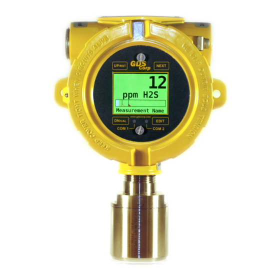
GASMAX CX + GDS-IR Operation & Maintenance Manual, Revision 1.0 4 INITIAL STARTUP When power is applied to the GASMAX CX, the screen will show ‘GASMAX CX” followed by one or two Smart Sensor information screens if the sensor(s) are locally connected. Certain sensors may initially indicate off‐scale high or low values, but should quickly return to zero within a few minutes if no target gas is present. During this warm‐up delay period, the 4‐20mA output is held at 4.0 mA to eliminate false alarms in any receiving devices. GASMAX USER INTERFACE The GASMAX CX display is shown in Figure 5‐1. There are four magnetic switches on the face of the GASMAX CX, arranged in a quadrant around the LCD display; these are labeled NEXT, EDIT, DOWN/CAL and UP. To activate, or “press” a magnetic switch, swipe the magnetic wand near the switch. For the balance of this manual, the term “press” will be used to describe activation of any key via the magnetic wand. Figure 4-1: Gasmax Single Channel Display Pressing the NEXT key causes the GASMAX display to switch display screens. In single channel mode, the display will switch between DATA and TREND. In dual channel systems, the sequence will be: DATA 1, DATA 2, TREND 1, TREND 2, DUAL CHANNEL, followed by DATA 1. Figure 4-2: Gasmax Dual Channel Display ... -
Page 13: Figure 4-3: User Menu Screen
GASMAX CX + GDS-IR Operation & Maintenance Manual, Revision 1.0 Press the EDIT key to access the USER MENU display mode. When in user menu display mode, use UP and DOWN to select an item, EDIT to change an item, and NEXT to exit the menu or function and return the GASMAX CX to display mode. See Chapter 8 for more information on User Menus. Figure 4-3: User Menu Screen NOTE: TAKE CARE WHEN CHANGING GASMAX MENU SETTINGS – INCORRECT SETTINGS COULD CAUSE THE GASMAX TO BECOME INOPERATIVE AND MAY COMPROMISE THE SAFETY OF THE GAS DETECTION SYSTEM. BE SURE TO UNDERSTAND WHAT TO CHANGE AND WHY BEFORE ENTERING THE USER MENU. Press the DN/CAL key, followed by the EDIT key, to access CALIBRATION MODE. Regular calibration is critically important to the continued safe operation of any gas detection system. See Chapter 6 for more information on calibration. Then press the EDIT To access Cal key to confirm Mode, press the Calibration Mode DN/CAL key first Figure 4-4: Accessing Cal Mode NOTE: TAKE CARE WHEN APPLYING CALIBRATION GAS TO THE GASMAX WHILE NOT IN CALIBRATION MODE. THIS WILL CAUSE AN INCREASE IN THE 4‐20MA OUTPUT SIGNAL AND MAY RESULT IN ... -
Page 14: Figure 4-5: Gasmax Data Display
GASMAX CX + GDS-IR Operation & Maintenance Manual, Revision 1.0 MORE INFORMATION ON DISPLAY SCREENS The DATA display screen shows a single channel’s information. The current value is shown in calibrated engineering units. A horizontal bargraph tracks the current value and shows the Alarm 1 and Alarm 2 values in graphical form. The user‐programmable Engineering Units (“Eunits”) and Measurement Name text strings are shown below the real‐time reading. Above the LCD display, three LEDs indicate the status of the level and fault alarms. If relays are installed, the LEDs indicate whether the relays are active. Note that if any relay is set for FAILSAFE operation, if LED is ON the relay will be de‐energized. In dual channel mode, if either channel is in alarm the corresponding A1 or A2 indicator LED (and relay) will be energized. Engineering Units Value MODBUS Communications LEDs Horizontal Bargraph Alarm Levels “Measurement Name” Figure 4-5: GASMAX Data Display Two LEDs monitor the MODBUS RS‐485 transmit (TXD) and receive (RXD) buffers. Flashing indicates sent or received data. RXD will flash whenever a message from the MODBUS master is received and TXD will flash when any response message is transmitted from the GASMAX. Engineering Units 30 Minute Trend Alarm 2 Level (RED) Alarm 1 Level (YELLOW) Figure 4-6: GASMAX Trend Display ... - Page 15 GASMAX CX + GDS-IR Operation & Maintenance Manual, Revision 1.0 ALARM SETUP – ALARM 1, 2 AND 3 Each channel can be programmed for up to three independent alarm levels, and can be set to alarm ABOVE the target value for BELOW the target value. All programming is done in engineering units that correspond to the channels ZERO and SPAN settings. Alarm processing will trigger an alarm condition when the input exceeds the programmed value, and includes hysteresis to keep the alarm from rapidly switching ON and OFF if the input remains close to the programmed alarm value. NOTE: ALARM RELAYS ARE NORMALLY TRIGGERED IF EITHER CHANNEL 1 OR CHANNEL 2 ALARM THRESHOLDS ARE EXCEEDED. NOTE: IF THE OPTIONAL ALARM RELAYS ARE NOT INSTALLED, ALARM SETTINGS AFFECT THE OPERATION OF THE FRONT PANEL DISPLAY ONLY. SEPARATE ALARM SETTINGS MAY NEED TO BE PROGRAMMED IN THE 4‐20MA RECEIVING DEVICE. ALARM OPERATION – FAULT FAULT is typically used to indicate FAULT conditions that suggest sensor failure or “out of measurement range” conditions. SYSTEM SETUP Once operational, the user should verify the following settings prior to initial calibration: 1. Local time and date: Check date value and adjust time for proper time zone. 2. Tag name or Engineering Units settings: Edit values as necessary. 3. CAL SPAN GAS value: Set to match concentration of calibration gas cylinder. 4. CAL MARKER value: Adjust desired output mA during calibration. 5. ALARM 1, ALARM 2, ALARM 3 settings: Set for desired levels. NOTE: If relays are not installed, GASMAX CX programmable alarm levels affect operation of display color only (Sec 7‐3). ...
-
Page 16: Calibration
GASMAX CX + GDS-IR Operation & Maintenance Manual, Revision 1.0 5 CALIBRATION CALIBRATION OVERVIEW Calibration is critically important to ensure correct operation of the GASMAX CX. The built‐in CAL MODE function is designed to make calibration quick, easy and error free; a successful ZERO and SPAN calibration for the GASMAX CX requires only four keystrokes. During CAL MODE zero and span, the sensor output is disconnected and the GASMAX CX transmits a fixed mA value, called the CAL MARKER, to notify the receiving device that a calibration is in progress. During the following CAL PURGE DELAY time, the GASMAX CX transmits a fixed 4.0 mA signal to prevent external alarms during calibration. Always follow these general calibration guidelines: Calibration accuracy is only as good as the calibration gas accuracy. GDS Corp calibration gases are traceable to NIST (National Institute of Standards and Technology). Never use calibration gas that has passed its expiration date. Check the SPAN GAS VALUE setting and make sure it matches the calibration gas value. Always use a GDS Corp calibration cup or wrap that completely surrounds the sensor head. Be sure to use ZERO AIR, a mixture of 21% oxygen and 79% nitrogen, as a zero reference unless you are certain that no target gas exists in the area. Ambient gas may result in an ‘elevated zero’ condition that will cause a FAULT to occur once the ambient gas is no longer present. Always calibrate a new sensor before depending on the device for personnel or equipment safety Calibrate on a regular schedule. GDS Corp recommends a full calibration every 3 months, with periodic ‘bump tests’ on a more frequent basis to ensure that the sensor has not been affected by ... -
Page 17: Figure 5-2: Calibration Setup
GASMAX CX + GDS-IR Operation & Maintenance Manual, Revision 1.0 CALIBRATION PROCEDURE The GDS‐IR infrared sensor is highly stable and should not require calibration more than once every six months under normal conditions. However, each installation is unique and GDS Corp recommends performing a calibration upon initial startup and within 3 months. Allow at least 30 minutes from initial power‐up for the sensor to stabilize before beginning any calibration procedure! Before beginning calibration, make sure you have the following items: 1. Cylinder of calibration gas with fixed flow regulator (1.0 LPM is recommended) 2. Cylinder of ‘zero air’ for zero reference and span gas purge (if needed) 3. 3’ length of flexible tubing 4. GDS‐IR calibration wrap accessory (p/n 20‐0243) Flexible Tubing Regulator Cylinder of Span Gas or Zero Air Figure 5-2: Calibration Setup ... -
Page 18: Figure 5-3: Ir Zero For Local Sensors
GASMAX CX + GDS-IR Operation & Maintenance Manual, Revision 1.0 Local GDS‐IR Sensors are zero’d by placing a magnetic wand immediately next to the right side of the explosion proof enclosure as shown at right Figure 5-3: IR Zero for Local Sensors IR Zero Button GASMAX CX IR Zero Mag Switch IR Zero Mag IR Zero Button IR Zero Switch Mag Remote GDS‐IR Sensors can be Switch zero’d from either the GASMAX CX or remote Sensor Junction Box ... -
Page 19: Maintenance
GASMAX CX + GDS-IR Operation & Maintenance Manual, Revision 1.0 6 MAINTENANCE GASMAX CX Normal maintenance for the GASMAX CX primarily involves periodic calibration on standard intervals. GDS Corp recommends calibration at least every three months, or more often if temperature extremes, vibration, the presence of incompatible gases or other environmental factors may accelerate the deterioration of the sensor element. Calibration should also include inspections for clogged or wet sensor heads, cracked or damaged enclosures and water incursion inside conduit or junction boxes. GDS‐IR INFRARED SENSOR When power is applied to the GDS‐IR, it enters a one‐minute warm‐up period. The output current will be 0.8 mA during the warm up time period. At the end of the warm‐up period with no faults present, the GDS‐IR automatically enters normal operating mode and outputs 4.0 mA. If a fault is present after warm‐ up, the detector current output will indicate a fault. In the normal operating mode, the 4‐20 mA signal level Sensor Output: corresponds to the detected gas concentration. In the event 0.0 mA Unit Fault of an overrange gas release, the GDS‐IR will indicate an 0.2 mA Reference channel fault overrange condition up to approximately 23mA. Excessive 0.4 mA Analytical channel fault gas will not harm the sensor and the output will return to ... -
Page 20: Figure 6-1: Gds-Ir Disassembly
GASMAX CX + GDS-IR Operation & Maintenance Manual, Revision 1.0 Using the two wrenches, rotate the lower section of the optical waveguide such that it screws into the upper section. This will eventually allow the waveguide assembly to be removed from the GDS‐IR. 5. Using a cotton swab and alcohol, clean the surfaces of the Receiver and Source as shown. 6. Reassemble the GDS‐IR 7. Perform a ‘hardware zero’ once the sensor is completely reassembled. NOTE: IT IS NOT NECESSARY TO REMOVE POWER FROM THE GDS‐IR TO PERFORM THIS CLEANING PROCESS. Figure 6-1: GDS-IR Disassembly Page 20... -
Page 21: Troubleshooting
GASMAX CX + GDS-IR Operation & Maintenance Manual, Revision 1.0 7 TROUBLESHOOTING GASMAX CX SHOWS FAULT INDICATION ON LOCAL SENSOR Certain. Toxic sensors Sensor reading Sensor GASMAX CX SHOWS FAULT INDICATION ON REMOTE SENSOR Catalytic Sensor reading Sensor re RECEIVING DEVICE AND GASMAX CX DISPLAYED VALUES DON’T MATCH Check that zero and full scale range values match between GASMAX CX and receiving device (controller). Use DIAGNOSTICS menu to force GASMAX CX output to 12mA (1/2 scale) and verify appropriate half‐scale reading on controller. Check for high impedance shorts to ground on 4‐20mA wiring. If 4‐20mA output is off‐scale low or high and cannot be adjusted using DIAGNOSTICS mode, IO/Power Supply board may be defective and should be replaced. CONTROLLER MODBUS DATA INCORRECT ... - Page 22 GASMAX CX + GDS-IR Operation & Maintenance Manual, Revision 1.0 Note that a COLD BOOT will reset certain values to their default setting, including the MODBUS address value. If a Smart Sensor is connected to a local sensor head, the GASMAX will reload the sensor type, range, cal span value and other sensor –related values automatically. Page 22...
-
Page 23: Specifications
GASMAX CX + GDS-IR Operation & Maintenance Manual, Revision 1.0 8 SPECIFICATIONS Model GASMAX CX + GDS‐IR Infrared Sensor Power Input 18‐30VDC at < 10 watts with relay board. Display Full color LCD with engineering units, bargraph and 30‐minute trend Channel One Digital input for GDS Corp 10‐98xx Smart Toxic Sensors Input Bridge input for GDS Corp 10‐98xx Catalytic Bead, SmartIR or PID sensors Analog 4‐20mA input Channel Two GDS‐IR Infrared Sensor Input Accuracy ±3% of full scale for values up to 50% LEL, ±5% for values above 50% LEL Standard Three‐wire 4‐20mA current source outputs with fault and overrange indication. Output Maximum loop resistance is 750 ohms with standard 24VDC supply Optional Relay / MODBUS interface with 4x 5A SPDT programmable alarm relays Output Temperature Electronics ‐40°C to +60°C ... -
Page 24: Spare Parts
GASMAX CX + GDS-IR Operation & Maintenance Manual, Revision 1.0 9 SPARE PARTS Electronics Nest Assembly: 10‐0387 Display Board 10‐0388 Relay / MODBUS Board 10‐0390 Power / I/O Board 20‐0195 GDS‐IR Sensor Personality Board Yellow Enclosure: 10‐0160 GASMAX Enclosure GDS‐IR Sensor: GDS‐IR Part number determined by target gas type (Contact Factory for details) 20‐0236 Rain Shield 20‐0243 Calibration Wrap Figure 9-1: GASMAX CX + GDS-IR Local Sensor Spare Parts ... -
Page 25: Drawings And Dimensions
GASMAX CX + GDS-IR Operation & Maintenance Manual, Revision 1.0 10 DRAWINGS AND DIMENSIONS 5.25” 5.0” 12.25” Figure 10-1 GASMAX CX + GDS-IR DIMENSIONS (Vertical) Page 25 ... -
Page 26: Figure 10-2 Gasmax Cx + Gds-Ir Dimensions (Horizontal)
GASMAX CX + GDS-IR Operation & Maintenance Manual, Revision 1.0 12.25” 5.0” Figure 10-2 GASMAX CX + GDS-IR DIMENSIONS (Horizontal) Page 26... - Page 28 GDS Corp. 1245 Butler Road League City, TX 77573 409-927-2980 409-927-4180 (Fax) ww.gdscorp.com ...