Table of Contents
Advertisement
Quick Links
Instruction manual
Electronic cam control
LOCON 7 / LOCON 9
A UDIN Composants & systèmes d'automatisme
Siège :7 bis rue de Tinqueux - 51100 Reims - France - Tel : 03.26.04.20.21 - Fax : 03.26.04.28.20
Agence Nord : 66 rue J.Baptiste Lebas - 59910 Bondues - France Tel : 03.20.27.99.84 - Fax : 03.20.27.99.85
Web : http://www.audin.fr - Email : info@audin.fr
Advertisement
Table of Contents

Subscribe to Our Youtube Channel
Related Manuals for DEUTSCHMANN AUTOMATION LOCON 7


Summary of Contents for DEUTSCHMANN AUTOMATION LOCON 7
- Page 1 Instruction manual Electronic cam control LOCON 7 / LOCON 9 A UDIN Composants & systèmes d'automatisme Siège :7 bis rue de Tinqueux - 51100 Reims - France - Tel : 03.26.04.20.21 - Fax : 03.26.04.28.20 Agence Nord : 66 rue J.Baptiste Lebas - 59910 Bondues - France Tel : 03.20.27.99.84 - Fax : 03.20.27.99.85...
- Page 3 AUTOMATION reserves the right to carry out alterations to the described products in order to improve the reliability, function or design thereof. DEUTSCHMANN AUTOMATION only accepts liability to the extent as described in the terms and conditions of sale and delivery.
- Page 4 Deutschmann Automation GmbH & Co. KG Instruction manual LOCON 7, LOCON 9 V. 10.4 24.5.04...
-
Page 5: Table Of Contents
EMC Directives for products of Deutschmann Automation ..11 Cam control LOCON 7 and LOCON 9 ....12 Structure of the unit ......12 Pin assignment LOCON 7 and LOCON 9 . - Page 6 10 Technical data ......39 10.1 Technical data LOCON 7 ......39 10.2 Technische Daten LOCON 9 .
- Page 7 14.1 Description and connection of the DICNET®-Adapter ..49 14.1.1 DICNET®-Adapter DICADAP 3 ..... . . 49 24.5.04 Instruction manual LOCON 7, LOCON 9 V. 10.4...
- Page 8 Deutschmann Automation GmbH & Co. KG Instruction manual LOCON 7, LOCON 9 V. 10.4 24.5.04...
-
Page 9: Introduction
In such cases, the information applies to the entire model series. 1.1.3 Suggestions We are always pleased to receive suggestions and wishes etc. and endeavour to allow for these. It is also helpful if you bring our attention to any errors. 24.5.04 Instruction manual LOCON 7, LOCON 9 V. 10.4... -
Page 10: From The Mechanical System To An Electronic System
The output is switched on between these points. Thanks to twenty years of experience, consistent further development and the use of ultra-mod- ern technology, DEUTSCHMANN AUTOMATION has now become one of the leading suppliers of electronic cam controls. Deutschmann Automation’s range of products See our homepage at http://www.deutschmann.de. -
Page 11: Emc Directives For Products Of Deutschmann Automation
The installation of our products has to be carried out considering the relevant EMC directives as well as our internal instructions. For more information see ’EMC Directives’ on our homepage at http://www.deutschmann.de. 24.5.04 Instruction manual LOCON 7, LOCON 9 V. 10.4... -
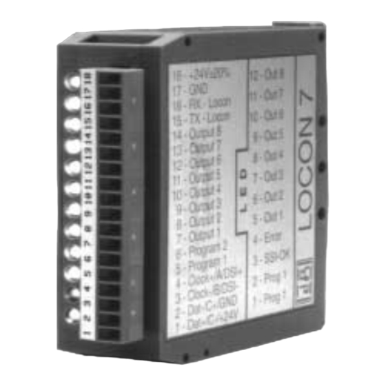
Page 12: Cam Control Locon 7 And Locon 9
Cam control LOCON 7 and LOCON 9 Deutschmann Automation GmbH & Co. KG 3 Cam control LOCON 7 and LOCON 9 Structure of the unit According to the picture below, the complete device is stored in a plastic housing for DIN-rail... -
Page 13: Display Elements Locon 7 And Locon 9
1 - 4 (see pin assignment). The output pins 7 - 14 of LOCON 7/9 are plus-switching 24V; that means an active output has a level of 24V compared with GND, a deleted output is high-ohmic. -
Page 14: Connecting The Serial Rs232-Interface
The following assignment applies: white = Tx-LOCON7 green = Rx-LOCON7 brown = Please note that at the RS232-interface the Tx-wire of one participant is con- nected with the Rx-wire of the other participant and vice versa. Instruction manual LOCON 7, LOCON 9 V. 10.4 24.5.04... -
Page 15: Networking Terminals With Cam Controls And Pcs
A cable that fully complies with these specifications and that has been developed specifically for use in field bus systems is the UNITRONIC®-BUS LD cable 2 x 2 x 0.22, available on a drum from LAPP KABEL in Stuttgart, or by the meter from Deutschmann Automation. 24.5.04... -
Page 16: Earthing, Shielding
DICNET up to a certain extent. Wherever possible, the RS232 interface should be used only for temporary connections (e. g. for connecting a PC). Instruction manual LOCON 7, LOCON 9 V. 10.4 24.5.04... -
Page 17: Connection Examples
Consequently, in the case of simple wiring with a LOCON and an external operator control panel, it is the obvious choice to use the same 24 V supply for both units. 24.5.04 Instruction manual LOCON 7, LOCON 9 V. 10.4... -
Page 18: Rs232 Link Locon - Term
The two ground potentials must be connected. Picture 4: RS232 link Terminal - LOCON The presented devices exemplary stand for Deutschmann terminals and cam controls of the series LOCON / ROTARNOCK respectively. Instruction manual LOCON 7, LOCON 9 V. 10.4 24.5.04... -
Page 19: Dicnet Link Locon - Term - Pc
PC is made at a serial port COMx - see the illustration below. Picture 5: Link DICNET bus to PC The presented devices exemplary stand for Deutschmann terminals and cam controls of the series LOCON / ROTARNOCK respectively. 24.5.04 Instruction manual LOCON 7, LOCON 9 V. 10.4... -
Page 20: Connecting The Encoder
With the input "CLEAR+" the count of LOCON 7/9 can be deleted, where you have to pay atten- tion, that the pulse width of the clear-signals is at least 1ms (at LOCON 7) or 1µs (at LOCON 9). With this mode it is possible to construct a very low-priced complete solution, since for instance an initiator or switch can be inserted as pulse encoder. -
Page 21: External Operating Unit Term 5
This external control- and display unit consists of a plastic housing with overall dimension W72 x H96 x D18 mm for front sheet installation. LOCON 7/9 can be programmed via 4 keys, 6 status LEDs, 16 output LEDs and a 6-digit seven- segment display as described in chapter "Programming LOCON 7 and LOCON 9". -
Page 22: Technical Dimensional Drawings
External operating unit TERM 5 Deutschmann Automation GmbH & Co. KG Technical dimensional drawings 5.3.1 TERM 5 / TERM 6 Picture 6: Technical dimensional drawing TERM 5 / TERM 6 Instruction manual LOCON 7, LOCON 9 V. 10.4 24.5.04... -
Page 23: Term 5-H / Term 6-H
Deutschmann Automation GmbH & Co. KG External operating unit TERM 5 5.3.2 TERM 5-H / TERM 6-H Picture 7: Technical dimensional drawing TERM 5-H / TERM 6-H 24.5.04 Instruction manual LOCON 7, LOCON 9 V. 10.4... -
Page 24: Term 5-T / Term 6-T
External operating unit TERM 5 Deutschmann Automation GmbH & Co. KG 5.3.3 TERM 5-T / TERM 6-T Picture 8: Technical dimensional drawing TERM 5-T / TERM 6-T Instruction manual LOCON 7, LOCON 9 V. 10.4 24.5.04... -
Page 25: Pin Assignment Term
Flashes together with the LED Function when programming the inversion of the rotational direction. LED Function At LOCON 7 without function, at LOCON 9 idle time indication. LED Error Flashes in case an error condition appeared. At the same time the correspond- ing error number is presented on the display, that is described more detailed in the appendix. -
Page 26: External Display Unit Term 4
D55 mm for front sheet installation. The unit has 4 seven-segment-displays and 2 status LEDs which characterize the position- and speed-display. The connection to LOCON 7 is made via the RS232-interface. Dimensional drawing TERM 4 Picture 10: TERM 4 Instruction manual LOCON 7, LOCON 9 V. 10.4... -
Page 27: Technical Dimensional Drawing
Pin assignment TERM 4 The connection is made via a 5 pol. plug (pin assignment identical to that of TERM 5) (see chap- ter "Pin assignment TERM 5/6" on page 25). 24.5.04 Instruction manual LOCON 7, LOCON 9 V. 10.4... -
Page 28: Programming Locon 7 And Locon 9
Therefore a fast change of the display in the whole field is guaranteed. Instruction manual LOCON 7, LOCON 9 V. 10.4 24.5.04... - Page 29 Deutschmann Automation GmbH & Co. KG Programming LOCON 7 and LOCON 9 O n l y L O C O N 9 24.5.04 Instruction manual LOCON 7, LOCON 9 V. 10.4...
-
Page 30: Definitions
A "blank-cam" is displayed by three horizontal dashes (“---“). It always appears, when no cam is programmed at the desired output or if a new cam can be added in the programming-activity. Instruction manual LOCON 7, LOCON 9 V. 10.4 24.5.04... -
Page 31: Zero Offset
If there are cams on the outputs in the displayed program, the LEDs "On" and "Off" light at the same time. Therefore it can be examined very fast, on which program values are programmed. The normal mode can be reached by pressing the key 24.5.04 Instruction manual LOCON 7, LOCON 9 V. 10.4... -
Page 32: Changing The Active Program
At first the starting point of the first cam is displayed, that is signalized by a flashing of the LED "On". Is none of the cams programmed, a blank-cam appears instead ("- - -"). Instruction manual LOCON 7, LOCON 9 V. 10.4 24.5.04... -
Page 33: Changing Existing Cams
The input of the values is carried out analogous to the procedure of changing the cams. If no more cams are to be completed, it is possible to return to the display mode with the key. 24.5.04 Instruction manual LOCON 7, LOCON 9 V. 10.4... -
Page 34: Teach-In Programming
100, must be opened for example at 1m/s at position 95, at 2m/s already at position 90. This function is called dynamic cam shift or idle time compensation (ITC). Instruction manual LOCON 7, LOCON 9 V. 10.4 24.5.04... -
Page 35: Program-Dependent Idle Times
The rotational direction of the connected encoder can be programmed by software. In the device’s state of delivery the rotational direction is not inverted. The display and programming of the inversion of the rotational direction takes place as follows: 24.5.04 Instruction manual LOCON 7, LOCON 9 V. 10.4... - Page 36 If the programming should be broken off, the old value can be restored with the key and a return to the normal mode can take place. Instruction manual LOCON 7, LOCON 9 V. 10.4 24.5.04...
-
Page 37: Initialization Of Encoder Resolution, Counting Area, Dicnet-Id
LOCON 9. There all parameters are queried interactively. After a change was made LOCON 9 carries out a warm start and reports the new parameters. 24.5.04 Instruction manual LOCON 7, LOCON 9 V. 10.4... -
Page 38: Commissioning
Checksum test and validity test of the EEROM Validity test of the cam program • Should errors occur during the self-test, these are presented on the display if possible (see chap- ter "Error messages"). Instruction manual LOCON 7, LOCON 9 V. 10.4 24.5.04... -
Page 39: Technical Data
External encoder position 2 displays for external ProgSelection1 SSI-control display 1 error display Interface RS232 (V. 24) Installation DIN-rail mounting Type of protection IP24 Dimensions 24 x 79 x 98 (WxHxD) 24.5.04 Instruction manual LOCON 7, LOCON 9 V. 10.4... -
Page 40: Technische Daten Locon 9
External encoder position 2 displays for external ProgSelection1 SSI-control display 1 error display Interface ® RS485 (DICNET Installation DIN-rail mounting Type of protection IP24 Dimensions 24 x 79 x 98 (WxHxD) Instruction manual LOCON 7, LOCON 9 V. 10.4 24.5.04... -
Page 41: Technical Data Term 4
Connections With screw-plug-connector Installation Front panel installation Type of protection IP54 Dimensions 48 x 96 x 55 mm (WxHxD) Switchgear opening 42 x 90 mm Operating voltage 10 - 30 VDC 24.5.04 Instruction manual LOCON 7, LOCON 9 V. 10.4... -
Page 42: Technical Data Term 5/6
Logic HIGH: > 16 volt < 10mA (typ. 5mA) Logic LOW: < 4 volt < 1mA 10.6 Conversion formula rev/min <--> Cycle time 60,000,000 Rev.max/min. = Cycle time [µs] x encoder revolution Instruction manual LOCON 7, LOCON 9 V. 10.4 24.5.04... -
Page 43: Error Messages
The corresponding output load must then be reduced and after that the error then be acknowl- edged. Only the overloaded output is switched off. The other outputs continue to operate. 24.5.04 Instruction manual LOCON 7, LOCON 9 V. 10.4... - Page 44 External fault signal (X26 only) Save blank cam Data record incomplete Direction-dependent output update illegal Outputs deactivated (brake cam option only) All outputs are switched briefly to 0 V when error 31 is acknowledged. Instruction manual LOCON 7, LOCON 9 V. 10.4 24.5.04...
-
Page 45: Error Number 100
LOCON 24, 48, 64 units with shown at the top right on the LCD (LOCON 32). LOCON encoder monitoring option) 24, 48, 64, see chapter Options: Encoder monitoring. SSI Time-out error SSI Gray code error 24.5.04 Instruction manual LOCON 7, LOCON 9 V. 10.4... -
Page 46: Error Number 200-299
Too many terminals in network (max. Reduce to 3 terminals 3 allowed) Max. 1 external terminal in the case of multiple-axis version of the LOCON 32 Internal error CMD UNKNOWN ERROR CMD CHECKSUM ERROR Instruction manual LOCON 7, LOCON 9 V. 10.4 24.5.04... -
Page 47: Communication Interface
Deutschmann Automation GmbH & Co. KG Communication interface 12 Communication interface Deutschmann Automation encourages the use of cam controls with remote control and display unit in order to meet market requirements. Since different combinations of cam control and terminal have been required repeatedly, specific to the particular application, it became necessary to define a standard interface (communication profile) supported by all terminals and cam controls from the Deutschmann Automation-range. -
Page 48: Servicing
The current software WINLOC is available for download from our Internet-homepage (URL). There you can also find topical information on Deutschmann products, instruction manuals and a list of our distribution partners. URL: www.deutschmann.de Instruction manual LOCON 7, LOCON 9 V. 10.4 24.5.04... -
Page 49: Appendix
WINDOWS-software "WINLOC" will be in the position to communicate with those control units from DEUTSCHMANN AUTOMATION, existing in the net through a serial interface (COMx). "WINLOC" is able to run under WIN 3.1x, WIN95/98 and WIN NT. The basic version is available free of charge. - Page 50 Appendix Deutschmann Automation GmbH & Co. KG Instruction manual LOCON 7, LOCON 9 V. 10.4 24.5.04...
Need help?
Do you have a question about the LOCON 7 and is the answer not in the manual?
Questions and answers