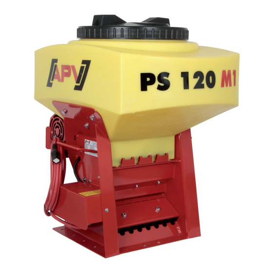
APV PS 120 M1 Operating Manual
Pneumatic seeder
Hide thumbs
Also See for PS 120 M1:
- Operating instructions manual (60 pages) ,
- Operating manual (48 pages)

Related Manuals for APV PS 120 M1


Summary of Contents for APV PS 120 M1
- Page 1 PNEUMATIC SEEDER PS 120 M1 – PS 500 M2 OPERATING MANUAL PLEASE READ CAREFULLY BEFORE INITIAL OPERATION! Translation of the original operating instructions Version: 5.0 EN; item number: 00602-3-578...
-
Page 2: Table Of Contents
TABLE OF CONTENTS GENERAL ............................4 About this operating manual....................4 Identification of the implement ....................4 Service ..........................5 EC Declaration of Conformity ....................5 DESCRIPTION ..........................6 Layout and functioning of the seed drill ................6 Layout and function of the hydraulic fan (HG 300 M1) ............7 Scope of delivery ......................... - Page 3 DECOMMISSIONING, STORAGE AND DISPOSAL..............35 Decommissioning the seed drill ..................35 Storage of the seed drill ..................... 36 Disposal ..........................36 APPENDIX ............................ 36 Accessories ........................36 9.1.1 Filling level sensor ......................36 9.1.2 Cable extension (6-pin) ...................... 36 9.1.3 Top link mounting kit for PS 120-500 ................. 36 9.1.4 Electric fan PLUS conversion kit ..................
-
Page 4: General
ABOUT THIS OPERATING MANUAL Validity and purpose This operating manual is valid for seed drills manufactured by APV with the type designations PS 120 M1 – PS 500 M2. This operating manual provides anyone who will be handling the seed drill with the required information to be able to perform the following tasks properly and safely: ... -
Page 5: Service
EC DECLARATION OF CONFORMITY Manufacturer APV - Technische Produkte GmbH Zentrale: Dallein 15 A-3753 Hötzelsdorf AUSTRIA Implement This Declaration of Conformity is valid for the following implements: Pneumatic seeder of type PS 120 M1, PS 120 M1 D, PS 120 M1 MG... -
Page 6: Description
The seed drill PS 120 M1 - PS 500 M2 The seeder with the type designations PS 120 M1 - PS 500 M2 is a pneumatic seeder with electric seeding shaft drive. It is used to spread seed on grassland and cropland. -
Page 7: Layout And Function Of The Hydraulic Fan (Hg 300 M1)
Designation Function Steel rack Hanging and connecting components of the seed drill. Hose clamping plate Clamping the seed tube hoses onto the steel rack. Electric fan Producing compressed air for conveying the seed. Electric fan PLUS Producing compressed air for conveying the seed. -
Page 8: Scope Of Delivery
(120 l, 200 l, 300 l, 500 l) and the possible types of spreading material (seed, fertilizer (D), micropellets (MG)). The following versions of the pneumatic seeder are available: PS 120 M1, PS 120 M1 D, PS 120 M1 MG PS 200 M1, PS 200 M1 D, PS 200 M1 MG ... -
Page 9: Safety
Implement version Size Value Weight 93 kg Dimensions (H × W × D in cm) 125 × 80 × 120 Implement version Size Value Hydraulic Fan (HG) Weight 23 kg Dimensions (H × W × D in cm) 27 × 46 × 40 Implement version Size Value... -
Page 10: Basic Safety Regulations
Safety instructions are information that serve to prevent personal injuries. Safety instructions contain the following information: Type of danger Possible consequences in case of non-compliance with the instructions Measures to prevent personal injury BASIC SAFETY REGULATIONS Target group for these regulations These regulations are aimed at all those who will be handling the seed drill. -
Page 11: Intended Use
INTENDED USE The pneumatic seeders of types PS 120 to PS 500 serve to spread seed with different properties and grain sizes on open fields. The implements are designed solely for normal use in agricultural operations. Only cereal varieties that are intended by the manufacturer and listed in the operating manual may be used. -
Page 12: Safety Devices
SAFETY DEVICES Meaning of the safety devices The seed drill has safety devices that protect the user from danger. It is mandatory to check that all safety devices are equipped and functional each time the seed drill is used. Location of the guards The picture shows the location of the safety devices: Function of the safety devices The safety devices have the following function:... -
Page 13: Dangers And Safety Measures
Appearance of the sign Meaning of the sign Read and observe the operating manual before working with the implement! Operating errors can lead to serious injuries. Risk of injury due to rotating parts! Do not reach into rotating parts. When working on the implement, switch these off and disconnect from the power supply. - Page 14 Transport Danger Where and in which situations Countermeasure does the danger occur? Risk of crushing due to the When lifting and lowering the The implement may only be weight of the implement implement transported by personnel trained for this task. Installation Danger Where and in which situations...
-
Page 15: Transport, Installation And Commissioning
Where and in which situations Danger Countermeasure does the danger occur? Hearing damage due to When operating the implement Use hearing protection. implement noise Risk of poisoning or suffocation While spreading seed. Wear a face mask when handling due to poisonous seed types toxic seed types. -
Page 16: Attaching The Seed Drill To A Tractor
Overview Designation Counter plate Seed drill Soil tillage implement Procedure To attach the seed drill on a soil tillage implement: Step Description Fasten the counter plate (1) on the soil tillage implement (3). The counter plate must be parallel to the ground when the soil tillage implement is in working position. -
Page 17: Installing The Dispersion Plates On The Soil Tillage Implement
Overview Designation Top link mounting kit Seed drill Procedure To attach the seed drill to a tractor using the top link mounting kit: Step Description Fasten the top link mounting kit (1) with bolts and nuts onto the seed drill (2). Fasten the top link (1) with the bolts onto the tractor. -
Page 18: Connecting The Hoses
Step Description Explanation/illustration Using the pliers, bend the tabs on the sides of the Result: dispersion plates down by 80°. Distribute the dispersion plates evenly across the entire working width of the soil tillage implement. Maximum spacing of the dispersion plates: 75 cm Push the hexagon shaft through the two hexagonal holes in the tabs on the sides of the dispersion plate intended for this purpose. -
Page 19: Removing The Swell Air Plate
Version 1 (Standard PS and MG): Step Description Illustration Using the cutting tool, cut eight pieces from the hose roll in the respectively required lengths. Slightly loosen the clamping screws (1) on the clamping plate with a WAF17 hexagon key. Insert the ends of the hoses into the transition pieces (2) up to the stop. -
Page 20: Connecting The Hydraulic Fan (Hf)
Required components, tools and materials For this work step, the following components, tools and materials are required: Hexagon key Torx screwdriver TX 30 Procedure This is how you remove the swell air plate: Step Description Explanation Loosen the hexagonal bolt (2) on the calibration slide (1). -
Page 21: Connecting The Electric Fan Plus
Designation Flow control valve Coupling sleeve (alternative) Coupler plug Return line Pressure line Procedure This is how to connect the hydraulic fan: Step Description Completely close the flow control valve (2) on the hydraulic block (1). Connect the return line (5) (marked in yellow, BG4) without reduction to the return flow connection of the tractor hydraulic system. -
Page 22: Operation
Step Description Explanation Connect the power supply cable (5) between the motor module (4) and the tractor cable set (1). Connect the implement cable (6) to Control Box (7). 5.2 Control Box: Select Electric PLUS in the 1. Fan motor menu. ISOBUS: Select Electric fan PLUS in the PS fan menu. - Page 23 Overview Designation Hydraulic block Flow control valve Procedure This is how to set the hydraulic fan: Version 1 (Constant pressure pump – non-adjustable oil quantity on the tractor) Step Description Completely close the flow control valve (2) on the hydraulic block (1). Start up the blower fan (tractor engine speed as in field operation).
-
Page 24: Setting And Adjusting The Spread Rate
Working width 12 m Seed Rate Pressure Speed Coarse seed 100 kg/ha 41 bar 4300 rpm SETTING AND ADJUSTING THE SPREAD RATE Purpose The setting for the spread rate, which is spread by the seed drill during the seeding process, has a significant effect on the seeding results. -
Page 25: Selecting The Right Seeding Shaft
Procedure This is how to perform a calibration test: Step Description Explanation Loosen the hexagonal bolt (2) on the calibration slide (1). Take the calibration slide out of the anchoring and turn it by 180°. Attach the rotated calibration slide back onto the Result: seeder. -
Page 26: Changing The Seeding Shaft
Standard equipment D series standard equipment fb-f-fb-fb fb-f-fb-fb fb-Flex20-fb White mustard Grass Micro granules Micro granules fertiliser fertiliser Phacelia Cereals White mustard Peas Phacelia Beans Available as an option fb-fb-ef-eb-fb fb-efv-efv-fb ffff GB-G-GB... - Page 27 The seed hopper is empty, see Emptying the seed hopper on page 34 for more information. The right seeding shaft is selected and ready, see Selecting the right seeding shaft on page 25 for more information. Required components, tools and materials For this work step, the following components, tools and materials are required: ...
-
Page 28: Checking The Ease Of Motion Of The Seeding Shaft
Step Description Explanation Remove the bearing flange (5). Result: Take out the seeding shaft. NOTE: Residual seed can fall out in the process. Insert the new seeding shaft with the free journal forwards into the steel rack. Turn the seeding shaft until the fitted key of the gearbox motor engages in the groove of the seeding shaft. -
Page 29: Setting The Brush Pressure
Step Description Switch on the seed drill. Perform the hearing test. If the sound of the running seeding shaft is noticeably loud or irregular, contact the maintenance and repair service, see Contact service on page 5 for more information. SETTING THE BRUSH PRESSURE Purpose The brush pressure on the seeding shaft is regulated using the brush adjustment lever. -
Page 30: Deactivating The Agitator
Required components, tools and materials For this work step, the following components, tools and materials are required: Seed Overview Designation Seed hopper lid Seed hopper Procedure This is how to fill the seed hopper: Step Description Explanation To open the seed hopper, turn the lid (1) counterclockwise. -
Page 31: 5.10 Display On The Motor Module
Overview Designation Bearing cover Hexagon key holder Lid nuts Agitator Seeding shaft Procedure This is how to deactivate the agitator: Step Description Explanation Open the bearing cover (1). To do so, loosen the cover nuts (3) with the hexagon key. Release the drive belt (7) from the seeding shaft driving wheel (8) and the agitator driving wheel (6) and put it aside. -
Page 32: Fault Indications
Required components, tools and materials For this work step, the following components, tools and materials are required: Use of the electric fan PLUS with 5.2 Control Box or ISOBUS Overview Designation Meaning Fan overload control lamp The LED lights up red if on of the motors is strained at its limits for too long. -
Page 33: Cleaning, Maintenance, And Repairs
Problem Cause Remedy Check the cabling. Control Box issues error Faulty cabling. If only one fan is running, both message Error (fan)!, control lamp E02 (Fan not connected) connection lines must lights up red on the motor connected to this fan. module. -
Page 34: Emptying The Seed Hopper
Step Description 5.2 Control Box: Pull out the power supply plug from the Control Box For the electric fan PLUS, also pull out the power supply plug for the motor modules from the seeder. ISOBUS: Disconnect the plug from the tractor socket. EMPTYING THE SEED HOPPER Purpose Before cleaning or decommissioning, the seed remaining in the seeder must be removed from the seed... -
Page 35: Checking The Hydraulic Hoses
Required components, tools and materials For this work step, the following components, tools and materials are required: Air compressor Moist cloth Procedure To clean the seed drill: Step Description Explanation Empty the seed hopper, see Emptying the seed hopper on page 34 for more information. Remove the seeding shaft, see Changing the seeding shaft for more information. -
Page 36: Storage Of The Seed Drill
Step Description Set the brush adjustment lever to Position "+4". Store the seed drill in a dry place to prevent the formation of germs inside the implement. STORAGE OF THE SEED DRILL For storage of the spreader, observe the following: ... -
Page 37: Electric Fan Plus Conversion Kit
9.1.4 ELECTRIC FAN PLUS CONVERSION KIT With this conversion kit, you can convert the electric or hydraulic fan on a PS to an electric fan PLUS. Order number: Item no.: 04000-2-882 CONNECTION DIAGRAM 9.2.1 GENERAL Electric fan: Hydraulic fan:... - Page 38 Cross-section Number Description Colour 1.1.1 Blue 1.1.2 Fan PLUS Blue 1.1.3 Fan speed sensor Brown 0.34 Fill level sensor Brown 0.34 Implement cable Blue Seeding shaft motor Black 2.1.1 Brown 2.1.2 Fan PLUS Brown Implement cable Brown Implement cable Blue Seeding shaft motor 4.1.1 Fan PLUS...
-
Page 39: Ps With Isobus
9.2.2 PS WITH ISOBUS Electric fan: Hydraulic fan:... - Page 40 Cross- Number Description Colour section Function Implement cable Red-yellow Seeding shaft motor Black Seeding shaft PWM Implement cable Red-green Implement cable Black Seeding shaft motor Ground Calibration button Black 0.75 Implement cable 0.75 4.2.1 Motor module Blue 4.2.2 Fan speed sensor Brown 0.34 +12 V sensor supply...
-
Page 41: Hydraulic Diagram
HYDRAULIC DIAGRAM Pos. Description G ½" (bolted connection XGE 15 LR-ED) Max. hose length 1 m Motor-side connection B G ½" (bolted connection XGE 15 LR-ED) Max. hose length 1 m Motor-side connection A G ½" (bolted connection XGE 18 LR-ED) Max. -
Page 42: Seeding Tables
SEEDING TABLES Weizen Grass Triticum Lolium perenne Rate kg/min kg/min kg/min kg/min kg/min kg/min kg/min Seeding ffff fb-Flex20-fb Flex40 ffff BG-G-BG shaft 0.13 0.52 0.34 0.48 0.06 0.26 0.27 0.16 1.18 0.58 1.03 0.22 0.45 0.61 0.20 2.30 0.99 1.95 0.49 0.76 1.17... - Page 43 Hafer Barley Rettich Perennial rye Avena Hordeum Raphanus raphanistrum Secale cereale Quantity kg/min kg/min kg/min kg/min kg/min kg/min kg/min Seeding fb-f-fb-fb ffff ffff shaft 0.01 0.15 0.18 0.54 0.24 0.66 0.46 0.02 0.46 0.48 0.87 0.62 1.18 0.99 0.04 0.98 0.97 1.41 1.27...
- Page 44 Rate kg/min kg/min kg/min kg/min kg/min kg/min kg/min Seeding fb-f-fb-fb ffff fb-f-fb-fb ffff fb-Flex20-fb Flex40 fb-fb-ef-eb-fb shaft 0.04 0.56 0.14 0.34 0.46 0.95 0.03 0.15 1.37 0.31 0.77 0.67 1.45 0.05 0.33 2.72 0.61 1.49 1.02 2.29 0.08 0.70 5.41 1.19 2.94 1.72...
- Page 45 DC25 bulk DC37 bulk PHYSIOSTART Rate kg/min kg/min kg/min kg/min kg/min kg/min kg/min Seeding fb-Flex20-fb Flex40 fb-fv-fv-fb fb-f-fb-fb fb-Flex20-fb shaft 0.90 0.62 1.38 0.60 0.16 0.21 0.61 1.81 0.93 2.04 1.64 0.25 0.30 0.93 3.82 1.43 3.15 3.05 0.41 0.46 1.45 6.90 2.45...
-
Page 46: Index
INDEX About this operating manual ......4 General ............. 4 Appendix ............36 Hydraulic diagram ........... 41 Attaching the seed drill to a soil tillage Identification of the implement......4 implement ........... 15 Installing the dispersion plates on the soil tillage Attaching the seed drill to a tractor .... - Page 47 NOTES...
- Page 48 APV – Technische Produkte GmbH Zentrale: Dallein 15 AT - 3753 Hötzelsdorf Tel.: +43 2913 8001 office@apv.at www.apv.at...
Need help?
Do you have a question about the PS 120 M1 and is the answer not in the manual?
Questions and answers