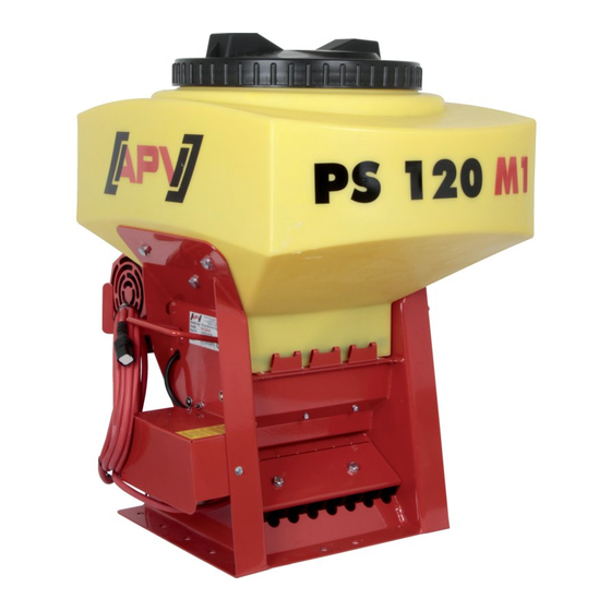
APV PS 120 M1 Operating Manual
Pneumatic seeder
Hide thumbs
Also See for PS 120 M1:
- Operating instructions manual (60 pages) ,
- Operating manual (48 pages)

Related Manuals for APV PS 120 M1


Summary of Contents for APV PS 120 M1
- Page 1 PNEUMATIC SEEDER PS 120 M1 – PS 500 M2 OPERATING MANUAL PLEASE READ CAREFULLY BEFORE START-UP! Translation of the original operating manual Version: 5.0 EN-US; item number: 00602-3-579...
-
Page 2: Table Of Contents
TABLE OF CONTENTS GENERAL INFORMATION ......................4 About this operating manual....................4 Identification of the implement ....................4 Service ..........................5 EC Declaration of Conformity ....................5 DESCRIPTION ..........................6 Structure and function of the seeder ..................6 Structure and function of the hydraulic fan (HG 300 M1) ............7 Scope of delivery ......................... - Page 3 DECOMMISSIONING, STORAGE, AND DISPOSAL..............35 Taking the seeder out of service ..................35 Storing the seeder ......................35 Disposal ..........................36 APPENDIX ............................ 36 Accessories ........................36 9.1.1 Fill level sensor ........................36 9.1.2 Cable extension (6-pin) ...................... 36 9.1.3 Top link mounting kit PS120-500 ..................36 9.1.4 Retrofit kit for electric fan PLUS ..................
-
Page 4: General Information
ABOUT THIS OPERATING MANUAL Validity and purpose This operating manual is valid for seeders manufactured by APV with the type designations PS 120 M1 to PS 500 M2. This operating manual provides anyone who will be handling the seeder with the information required to perform the following tasks properly and safely: ... -
Page 5: Service
EC DECLARATION OF CONFORMITY Manufacturer APV - Technische Produkte GmbH Headquarters: Dallein 15 3753 Hötzelsdorf AUSTRIA Implement This Declaration of Conformity is valid for the following implements: Pneumatic seeder, type PS 120 M1, PS 120 M1 D, PS 120 M1 MG... -
Page 6: Description
The seeders PS 120 M1 to PS 500 M2 The seeders with the type designations PS 120 M1 to PS 500 M2 are pneumatic seeders with an electric seeding shaft drive. They are used to spread seed on grassland and cropland. -
Page 7: Structure And Function Of The Hydraulic Fan (Hg 300 M1)
Designation Function Operating manual tube For stowing the operating manual Steel rack For hanging up and connecting seeder components. Hose clamp plate Clamps the seed hoses on the steel rack. Electric fan Provides compressed for feeding the seed. ... -
Page 8: Scope Of Delivery
Dünger, the German word for fertilizer), and micro granules (MG)). The following variants of the pneumatic seeder are available: PS 120 M1, PS 120 M1 D, PS 120 M1 MG PS 200 M1, PS 200 M1 D, PS 200 M1 MG ... -
Page 9: Safety
Implement variant Size Value PS 500 M2 (D/MG) Max. hopper content 500 l Weight 93 kg Dimensions (H × W × D in cm) 125 × 80 × 120 Implement variant Size Value Hydraulic fan (HG) Weight 23 kg Dimensions (H × W × D in cm) 27 ×... -
Page 10: Basic Safety Instructions
Safety notices are information notices that are designed to prevent injury. Safety notices show the following information: Type of danger Possible consequences if the notice is not complied with Measures to avoid injury BASIC SAFETY INSTRUCTIONS Target group for these instructions These instructions are intended for all persons who handle the seeder. -
Page 11: Intended Use
INTENDED USE The pneumatic seeders, types PS 120 to PS 500, are used to spread seed with different properties and grain sizes on open fields. The implements are designed exclusively for customary use in agricultural tasks. Only seeds of the grain varieties that are intended by the manufacturer and listed in the operating manual may be used. -
Page 12: Safety Devices
Face mask Safety footwear with non-slip soles SAFETY DEVICES Meaning of the safety devices The seeder has safety devices that protect the user from hazards. Each time before operation, all safety devices must always be checked for presence and function. Position of the safety devices The graphic shows the position of the safety devices: Function of the safety devices... - Page 13 Appearance of the sign Meaning of the sign Read and comply with the operating manual before start-up! Read and comply with the operating manual before working with the implement! Operating errors can result in serious injuries. Risk of injury due to rotating parts! Do not reach into rotating parts.
-
Page 14: Dangers And Safety Measures
DANGERS AND SAFETY MEASURES Overview The seeder is designed such that the user is protected from all dangers that can be avoided with reasonable design measures. However, due to the purpose of the seeder, there are residual risks that require implementation of precautionary measures, to be avoided. The nature of these residual risks and their effects are described below. -
Page 15: Transport, Installation, And Commissioning
Where and in what situations Danger Countermeasure does the danger occur? Risk of injury due to ejected seed While spreading seed. Always ensure that no one is in the spreading range of the implement. Risk of slipping, stumbling, and When handling the implement Only enter the implement area falling during its operation... -
Page 16: Fastening The Seeder On A Tractor
Overview Designation Counter plate Seeder Soil tillage implement Procedure This is how to fasten the seeder on a soil tillage implement: Step Description Fasten the counter plate (1) on the soil tillage implement (3). The counter plate must be parallel to the ground, when the soil tillage implement is in work position. -
Page 17: Mounting Dispersion Plates On The Soil Tillage Implement
Overview Designation Top link mounting kit Seeder Procedure This is how to fasten the seeder on a tractor using the top link mounting kit: Step Description Fasten the top link mounting kit (1) on the seeder (2) with bolts and nuts. Use the bolts to fasten the top link (1) on the tractor. -
Page 18: Connecting Hoses
Step Description Explanation/illustration Use the pliers to bend down the tabs on the sides Result: of the dispersion plates by 80°. Distribute the dispersion plates uniformly across the entire working width of the soil tillage implement. Maximum spacing of the dispersion plates: 75 cm Slide the hexagon shaft through the two hexagon holes in the lateral tabs of the dispersion plates intended for this purpose. -
Page 19: Removing The Swell Air Plate
Variant 1 (Standard PS and MG): Step Description Illustration Use the cutting tool to cut off eight hose sections from the hose roll, each in the suitable length. Use a hexagon wrench AF17 to slightly unscrew the clamping screws (1) on the clamping plate. Introduce the ends of the hoses into the transition pieces (2) to the stop. -
Page 20: Connecting The Hydraulic Fan (Hg)
Required components, tools, and materials For this work step, the following components, tools, and materials are required: Hexagon wrench Torx screwdriver TX 30 Procedure This is how to remove the swell air plate: Step Description Explanation Unscrew the hexagon bolt (2) on the calibration slide (1). -
Page 21: Connecting The Electric Fan Plus
Designation Flow control valve Coupling sleeve (alternative) Coupling connector Return line Pressure line Procedure This is how to connect the hydraulic fan: Step Description Completely close the flow control valve (2) on the hydraulic block (1). Connect the return line (5) (marked in yellow, BG4) without reducer, to the return flow connection of the tractor hydraulic system. -
Page 22: Operation
Step Description Explanation Connect the power supply cable (5) between the motor module (4) and the tractor cable set (1). Connect the implement cable (6) to the Control Box (7). 5.2 Controller: Select Electric PLUS in the menu 1. Motor fan. ISOBUS: Select Electric fan PLUS in the menu PS fan. - Page 23 Overview Designation Hydraulic block Flow control valve Procedure This is how to adjust the hydraulic fan: Variant 1 (fixed displacement pump – oil quantity cannot be adjusted on the tractor) Step Description Completely close the flow control valve (2) on the hydraulic block (1). Start up the blower fan (tractor engine speed as in field operation).
-
Page 24: Setting And Adjusting The Spread Rate
Working width 12 m Seed Quantity Pressure Speed Coarse seed 100 kg/ha 41 bar 4300 rpm SETTING AND ADJUSTING THE SPREAD RATE Purpose The setting for the spread rate, which is spread by the seeder during the seeding process, has a crucial effect on the seeding results. -
Page 25: Selecting A Suitable Seeding Shaft
Procedure This is how to perform a calibration test: Step Description Explanation Unscrew the hexagon bolt (2) on the calibration slide (1). Take the calibration slide out of the anchoring and turn it by 180°. Attach the rotated calibration slide back onto the Result: seeder. -
Page 26: Changing The Seeding Shaft
Standard equipment D series standard equipment fb-f-fb-fb fb-f-fb-fb fb-Flex20-fb White mustard Grass Micro granule Micro granule fertilizer fertilizer Phacelia Cereals White mustard Peas Phacelia Beans Available as an option fb-fb-ef-eb-fb fb-efv-efv-fb ffff GB-G-GB... - Page 27 The seed hopper must be empty, see Emptying the seed hopper on page 34 for more information in this regard. The suitable seeding shaft must have been selected and must be ready, see Selecting the right seeding shaft on page 25 for more information in this regard. Required components, tools, and materials For this work step, the following components, tools, and materials are required: ...
-
Page 28: Checking The Ease Of Movement Of The Seeding Shaft
Step Description Explanation Take off the bearing flange (5). Result: Take out the seeding shaft. NOTE: Residual seed can fall out in this process. Introduce the new seeding shaft with the free journal forward into the steel frame. Turn the seeding shaft until the feather key of the gear motor engages in the groove of the seeding shaft. -
Page 29: Setting The Brush Pressure
Procedure This is how to check the ease of movement of the seeding shaft: Step Description Switch on the seeder. Perform the noise check. If the sound of the running seeding shaft is noticeably loud or irregular, contact the maintenance and repair service, see Commissioning the Service organization on page 5 for more information in this regard. -
Page 30: Deactivating The Agitator
Prerequisites The following prerequisite must be met for this work step: The implement must be de-energized, see De-energizing the seeder on page 33. Required components, tools, and materials For this work step, the following components, tools, and materials are required: ... -
Page 31: 5.10 Display On The Motor Module
Overview Designation Bearing cover Hexagon wrench holder Cover nuts Agitator Seeding shaft Procedure This is how to deactivate the agitator: Step Description Explanation Open the bearing cover (1). To do this, unscrew the cover nuts (3) with the hexagon wrench. Detach the drive belt (7) from the seeding shaft driving wheel (8) and the agitator driving wheel (6) and put it in a safe place. -
Page 32: Faults
Required components, tools, and materials For this work step, the following components, tools, and materials are required: Use of the electric fan PLUS with a 5.2 controller or ISOBUS Overview Designation Meaning Indicator light Fan overloaded The LED lights up red, if one of the motors is under load too long in the limit range. -
Page 33: Cleaning, Maintenance, And Repair
Problem Cause Rectification Check cabling. Output fault message Fault (fan)! Faulty cabling. If only one fan is operated, both on the Control Box, on the motor module indicator light E02 (Fan connecting lines must not connected) lights up red. connected to this fan. -
Page 34: Emptying The Seed Hopper
EMPTYING THE SEED HOPPER Purpose Before cleaning or decommissioning, the seed remaining in the seeder must be removed from the seed hopper. Prerequisites The following prerequisite must be met for this work step: The implement must be de-energized, see De-energizing the seeder on page 33. Required components, tools, and materials For this work step, the following components, tools, and materials are required: None... -
Page 35: Checking The Hydraulic Hoses
Step Description Explanation Empty the seed hopper, see Emptying the seed hopper on page 34 for more information in this regard. Remove the seeding shaft, see Changing the seeding shaft for more information in this regard. Turn the seed hopper cover counterclockwise to open it. -
Page 36: Disposal
The implement must be stored in a dry and weather-protected location, on level and paved ground so that it does not lose its functionality, even during a longer storage period. Secure the implement such that it is stable and cannot fall over or roll. ... -
Page 37: Retrofit Kit For Electric Fan Plus
9.1.4 RETROFIT KIT FOR ELECTRIC FAN PLUS With this retrofit kit, you can convert the electric fan or hydraulic fan of a pneumatic seeder to an electric fan PLUS. Order number: Item no.: 04000-2-882 CONNECTION DIAGRAM 9.2.1 GENERAL Electric fan: Hydraulic fan:... - Page 38 Cross-section Number Description Color 1.1.1 Blue 1.1.2 Fan PLUS Blue 1.1.3 Fan speed sensor Brown 0.34 Fill level sensor Brown 0.34 Implement cable Blue Seeding shaft motor Black 2.1.1 Brown 2.1.2 Fan PLUS Brown Implement cable Brown Implement cable Blue Seeding shaft motor 4.1.1 Fan PLUS...
-
Page 39: Ps With Isobus
9.2.2 PS WITH ISOBUS Electric fan: Hydraulic fan:... - Page 40 Cross- Number Description Color section Function Implement cable Red-yellow Seeding shaft motor Black PWM seeding shaft Implement cable Red-green Implement cable Black Seeding shaft motor Ground Calibration button Black 0.75 Implement cable 0.75 4.2.1 Motor module Blue 4.2.2 Fan speed sensor Brown 0.34 +12 V sensor supply...
-
Page 41: Hydraulic System Diagram
HYDRAULIC SYSTEM DIAGRAM Item Description G ½" (threaded fitting XGE 15 LR-ED) Hose length max. 1 m Motor-side connection B G ½" (threaded fitting XGE 15 LR-ED) Hose length max. 1 m Motor-side connection A G ½" (threaded fitting XGE 18 LR-ED) Hose length max. -
Page 42: Seeding Tables
SEEDING TABLES Wheat Grass Triticum Lolium perenne Quantity kg/min kg/min kg/min kg/min kg/min kg/min kg/min Seeding ffff fb-Flex20-fb Flex40 ffff BG-G-BG shaft 0.13 0.52 0.34 0.48 0.06 0.26 0.27 0.16 1.18 0.58 1.03 0.22 0.45 0.61 0.20 2.30 0.99 1.95 0.49 0.76 1.17... - Page 43 Oats Barley Radish Perennial rye Avena Hordeum Raphanus raphanistrum Secale cereale Quantity kg/min kg/min kg/min kg/min kg/min kg/min kg/min Seeding fb-f-fb-fb ffff ffff shaft 0.01 0.15 0.18 0.54 0.24 0.66 0.46 0.02 0.46 0.48 0.87 0.62 1.18 0.99 0.04 0.98 0.97 1.41 1.27...
- Page 44 Red clover Phacelia Poppy Trifolium Phacelia tanacetigolia Pisum sativum Papaver Quantity kg/min kg/min kg/min kg/min kg/min kg/min kg/min Seeding fb-f-fb-fb ffff fb-f-fb-fb ffff fb-Flex20-fb Flex40 fb-fb-ef-eb-fb shaft 0.04 0.56 0.14 0.34 0.46 0.95 0.03 0.15 1.37 0.31 0.77 0.67 1.45 0.05 0.33 2.72...
- Page 45 DC25 bulk DC37 bulk PHYSIOSTART Quantity kg/min kg/min kg/min kg/min kg/min kg/min kg/min Seeding fb-Flex20-fb Flex40 fb-fv-fv-fb fb-f-fb-fb fb-Flex20-fb shaft 0.90 0.62 1.38 0.60 0.16 0.21 0.61 1.81 0.93 2.04 1.64 0.25 0.30 0.93 3.82 1.43 3.15 3.05 0.41 0.46 1.45 6.90 2.45...
-
Page 46: Index
INDEX About this operating manual ......4 General information .......... 4 Adjusting the hydraulic fan (HG) ..... 22 Hydraulic system diagram ....... 41 Appendix ............36 Identification of the implement......4 Basic safety instructions ......... 10 Intended use ..........10, 11 Calibration test .......... - Page 47 NOTES...
- Page 48 APV – Technische Produkte GmbH Headquarters: Dallein 15 3753 Hötzelsdorf, Austria Tel.: +43 2913 8001 office@apv.at www.apv.at...
Need help?
Do you have a question about the PS 120 M1 and is the answer not in the manual?
Questions and answers