
Subscribe to Our Youtube Channel
Related Manuals for Kolver K-DUCER KDU-NT

Summary of Contents for Kolver K-DUCER KDU-NT
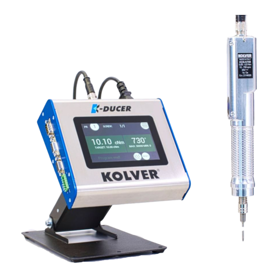
- Page 1 KDU-NT and KDS-NT* Torque range: 5 – 70 cNm, 7 – 100 ozfin OPERATOR MANUAL *Patent pending...
- Page 2 VIBRATION LEVEL: < 2.5 m/s² DECLARATION OF CONFORMITY KOLVER S.r.l. declares that the new tool here described: control unit model KDU-NT and screwdrivers KDS-NT series (see table) are in conformity with the following standards and other normative documents: 2006/42/CE, LVD 2014/35/UE, EMCD 2014/30/UE, EN 62841-2- 2:2014, EN 62841-1: 2015, EN 60204-1, EN 61000-6-2, EN 61000-6-4, 2011/65/UE (RoHS III).
-
Page 3: Declaration Of Use
We, KOLVER, cannot be held liable for the consequences of using the declared values, instead of values reflecting the actual exposure, in an individual risk assessment in a work place situation over which we have no control. -
Page 4: Table Of Contents
Table of Contents DECLARATION OF USE ....................... 3 INTRODUCTION ..........................6 MODELS............................... 6 INSTALLATION ..........................7 Installation of KDU-NT unit ......................7 Connectors ............................8 Installation of KDS screwdriver ....................10 Lever installation ........................10 Cable connection and part numbers ..................11 Installation of reaction arm ...................... - Page 5 ADVANCED TORQUE CONTROL STRATEGIES ..............37 RUNNING TORQUE ....................... 37 PREVAILING TORQUE ......................40 MULTI-STEP AND COMBINED PROGRAMS ..............41 MAIN MENU ..........................42 PROGRAMS menu ........................43 PROGRAMS menu tree ......................44 TORQUE & ANGLE menu ...................... 48 RAMP, TIME, & PV TORQUE menu ..................50 REV &...
-
Page 6: Introduction
Read the manual carefully and if unsure please contact Kolver for support. MODELS KDU-NT power supply and control unit:... -
Page 7: Installation
INSTALLATION Installation of KDU-NT unit The KDU-NT features rubber feet and a tilted screen and can be conveniently set on a flat surface. All dimensions are reported in mm. Vers. 111422... -
Page 8: Connectors
Also available separately: • vertically and horizontally adjustable bracket (part number 010401) • swivel table stand (part number 010402) 010401 010402 Connectors Vers. 111422... - Page 9 K-EXPAND software chapter. CN2 male serial connector To connect with a compatible barcode scanner, such as Kolver Barcode P/N 020050, serial printers such as Kolver PRNTR1, or serial terminals (PC/PLCs). CN3 female serial connector To connect with Kolver accessories SWBX88/CBX880, serial printers such as Kolver PRNTR1, or serial terminals (PC/PLCs).
-
Page 10: Installation Of Kds Screwdriver
Installation of KDS screwdriver Lever installation To install the lever kit (cod. 010450), simply remove the two M2.5 screws from the cover (cod. 250203), place the lever on top of the cover, and screw using the longer M2.5 screws provided with the lever kit. Vers. -
Page 11: Cable Connection And Part Numbers
Installation of reaction arm Kolver recommends always using a reaction arm to increase the precision of low torque tightenings and for the comfort of the operator. Fix the reaction arm to the indicated areas only, on the naked metal cylinder near the head of the screwdriver. - Page 12 Reaction arm mounting: Example of collaborative robot mounting (threaded tool-holders also available): Vers. 111422...
- Page 13 Threaded M3 fixturing holes (side holes on CA models only): Vers. 111422...
-
Page 14: Quick Start
QUICK START Turn the unit on through the on/off switch on the lower panel. The unit will carry a general system check and the words “NO SCREWDRIVER CONNECTED” will appear if no screwdriver is connected. You can still enter the main menu without any screwdriver connected. When a screwdriver is connected, it will be recognized by the unit and the "CONNECTED SCREWDRIVER"... - Page 15 If the parameters set in the current program are outside the allowable range of the connected screwdriver, the following screen will appear: To resolve the error, select a program previously configured for the connected screwdriver model, or enter the main menu to modify the parameter out of range for the current program.
- Page 16 In angle control: the maximum torque set in the program is equal or lower than the minimum limit of the screwdriver. TorqueMaxUnderMinLim In torque control: The maximum torque set in the program is equal or lower than the target torque already set. In angle control: the minimum torque set in the program is equal or higher than the maximum torque already set.
-
Page 17: Terminology
TERMINOLOGY KDU/K-DUCER/control unit: the KDU-NT control unit KDS/screwdriver: the transducerized screwdriving tool to be used with the KDU control unit Transducer: electronic component installed inside the KDS screwdriver which measures the torque in real time Tightening: the screwdriving cycle, from start (pressing of the lever or initiating remote lever control), to finish (automatic motor stop or lever or remote lever control release, whichever happens first) Rundown: the portion of the tightening cycle before reaching the seating point (the point... - Page 18 Angle: the revolutions of the tip of the screwdriver, in degrees. The starting point of the angle measurement depends on the settings chosen. Target angle: the angle measurement upon which the screwdriver motor will stop (angle control mode only), resulting in an “Angle OK” result if successful Angle control mode: a tightening where the screwdriver motor automatically stops upon reaching the target angle Run time: the duration of the tightening, in seconds...
-
Page 19: Operating The Kds Screwdriver
OPERATING THE KDS SCREWDRIVER Warning: Kolver strongly recommends using a reaction arm when applying torques lower than 0.30 Nm, to improve the precision of the torque applied by eliminating any effect and impulse from the operator’s wrist. Lever Press and hold the lever to initiate a tightening. - Page 20 Reverse button Press and hold the button to initiate a defix run, rotating in the opposite direction of the selected direction of rotation for the lever (see Programs menu > Other > ROTATION The behavior of the reverse button can be changed from the general settings menu (General Settings >...
-
Page 21: Operating The K-Ducer Control Unit
OPERATING THE K-DUCER CONTROL UNIT Main Screen – Program Mode – navigation tree (see Torque and Angle graphing for more information) Vers. 111422... -
Page 22: Main Screen - Program Mode
Main Screen – Program Mode Program (“PR”) number currently selected Touch to select a different program (1 through 64). Screw count Counter: screws successfully completed / number of screws in current program Note: does not appear if NUMBER OF SCREWS parameter is set to zero. Number of screws is also referred to as “batch size”... - Page 23 Torque charts Tap to display the Torque-time and torque-angle charts for last screw. Refer to Torque and Angle graphing for usage. Torque measurement unit You can select a different unit from the GENERAL SETTINGS menu. (10) Status bar Shows the last screw result or error messages (ready, screw OK, screw NOK, errors). (11) Torque target / bounds Shows the target torque when in torque control mode, or the min/max torque bounds...
-
Page 24: Main Screen - Sequence Mode - Navigation Tree
Main Screen – Sequence Mode – navigation tree (see Torque and Angle graphing for more information) Vers. 111422... -
Page 25: Main Screen - Sequence Mode
Main Screen – Sequence Mode Sequence (“SEQ”) currently selected Touch to select a different sequence (A through H). Screw count Counter: screws successfully completed / number of screws in current program Note: does not appear if NUMBER OF SCREWS parameter is set to zero. Number of screws is also referred to as “batch size”... - Page 26 Torque charts Tap to display the Torque-time and torque-angle charts for last screw. Refer to Torque and Angle graphing for usage. Torque measurement unit You can select a different unit from the GENERAL SETTINGS menu. (10) Status bar Shows the last screw result or error messages (ready, screw OK, screw NOK, errors). (11) Torque target / bounds Shows the target torque when in torque control mode, or the min/max torque bounds...
-
Page 27: Torque And Angle Graphing
Torque and Angle graphing The K-DUCER offers a powerful torque and angle graphing functionality, which can be used to study the characteristics of your fastening joint and optimize the PROGRAMS menu settings to maximize precision while minimizing assembly cycle time. The Torque and Angle graphing data for each tightening can also be saved with the screwdriving results, refer to the Retrieving and storing the screwdriving results... -
Page 28: Interpreting The Torque And Angle Charts
The graphs illustrated here were produced with a KDS-PL6/ESD screwdriver running on Kolver joint simulator (part number 240600) arranged in the semi-elastic configuration. We supplied additional hand-resistance to generate the “starting at” threshold. -
Page 29: Torque And Angle Charts With Running Torque
The graphs illustrated here were produced with a KDS-PL6/ESD screwdriver running on Kolver joint simulator (part number 240600) arranged in the semi-elastic configuration. We supplied additional hand-resistance to generate a non-zero “running torque” value and “starting at”... -
Page 30: Determining The Joint Type
(almost vertical). Left picture: Torque vs Time graph for a soft joint, generated using a KDS-PL6/ESD on Kolver joint simulator 240600. Right picture: Torque vs Time graph for a hard joint, generated using a KDS-PL6/ESD on a metal screw with non-locking washer on a threaded metal socket. -
Page 31: Determining The Appropriate Program Settings
These guidelines are always superseded by the specifications of the assembly joint and by all safety requirements of the operator and work environment. Kolver is not responsible for damages or injuries resulting from following these guidelines. Hard/inelastic joints These joints are best finished at low speed, to improve precision and avoid a high velocity impact at the end of the tightening. -
Page 32: Screwdriving Phases
Screwdriving Phases All colored circles in the diagram above represent configurable targets or thresholds. Phase Speed Halting Torque Halting Angle Pre-reverse Reverse speed Reverse Torque Pre-reverse setting Prevailing Torque Tightening speed* Highest torque Max angle (TC) achievable by KDS Target angle (AC) screwdriver Running Torque Tightening speed*... -
Page 33: Retrieving And Storing The Screwdriving Results
Via serial printer or serial terminal (CN2 or CN4) You can connect to CN2/CN4 with a serial printer (for example Kolver model PRNTR1) or with any serial terminals, for example Hyper Terminal, Realterm, or K-Expand for PC, to print the results of each tightening. - Page 34 Section Description Example Barcode Printout of the scanned barcode. In dual BC: 7612320103052 barcode modes, only the serial number barcode is printed. Result OK or NOK depending if tightening completed respecting the configured parameters Program The program number used for the tightening PR: 8 Model The screwdriver model used for the...
-
Page 35: Connecting A Barcode Scanner
63 characters or less for SERIAL NUMBER barcodes. Connect the barcode scanner to the CN2 9-pin male serial connector. If using a 2D barcode scanner such as Kolver P/N 020051, you must also connect the external power supply included with the scanner. - Page 36 Refer to the GENERAL SETTINGS menu and PROGRAMS menu chapters for information on how to configure the CBS880 accessory. If at any time: no bits are lifted, or more than one bit is lifted, or if REMOTE PR/SEQ is set to SWBX/CBS and an incorrect bit is lifted, the controller will remain locked.
-
Page 37: Configuring The K-Ducer
CONFIGURING THE K-DUCER ADVANCED TORQUE CONTROL STRATEGIES Certain applications may require the use of tightening strategies more advanced than target torque or angle control. For these applications, the K-DUCER offers Running Torque Compensate, Prevailing Torque, and multi-step program options. These terms are defined in the TERMINOLOGY section. - Page 38 Example Target torque: 2.22 Nm Seating point: 4000° Running torque estimate: 0.3 Nm (Running torque mode OFF) Test with running torque In the RAMP, TIME, & PV TORQUE menu configure the running torque WINDOW angle (or time), such that it always ends before the seating point. Use a window max value of at most the lowest seating angle point of the test tightening.
- Page 39 Example The running torque window was incorrect: it extended past the seating point. The severity of the problem was reduced by using the average running torque value. Note: if the running torque value is higher than the desired clamping torque value, you will also need to superimpose a prevailing torque phase to the running torque phase, to enable the screwdriver to finish the running torque phase at a higher torque value than the TARGET...
-
Page 40: Prevailing Torque
PREVAILING TORQUE Self-threading applications may require a prevailing torque strategy, if the initial torque required to overcome the self-threading action is higher than the target closing torque. Applications where the running torque value is expected to be higher than the clamping torque target may also require a prevailing torque phase, ending at or after the end of the running torque phase. -
Page 41: Multi-Step And Combined Programs
MULTI-STEP AND COMBINED PROGRAMS To reverse the screwdriver at the beginning of the tightening, or after reaching the closing torque, or to change the direction of tightening, refer to the corresponding options in the REV & PRE-REV menu. To combine multiple programs in a single tightening, you can configure a sequence with Program transition box set to “auto”. -
Page 42: Main Menu
Touch to enter the general settings menu, to configure general parameters such as passcode lock, I/O and MODBUS settings, kolver accessories, language, etc. Touch to enter the USB menu to save or load settings from a USB drive. Note: if a USB drive is connected, the unit automatically saves all screwdriving results in a text file. -
Page 43: Programs Menu
PROGRAMS menu Programs represent batches of one or more screws sharing the same parameters (torque, angle, speed, etc). With the K-DUCER series, you can define up to 64 different programs as well as assign a barcode to each for automatic selection with a barcode scanner. Tap the Programs button from the main menu to enter the programs menu. -
Page 44: Programs Menu Tree
PROGRAMS menu tree Vers. 111422... - Page 45 Vers. 111422...
- Page 46 Vers. 111422...
- Page 47 Vers. 111422...
-
Page 48: Torque & Angle Menu
TORQUE & ANGLE menu Note: carefully choosing the right combination of speed and downshift settings for the application will maximize the precision and lifetime of the tool while minimizing your assembly cycle time. Review the Determining the appropriate program settings section. - Page 49 If the (7) DOWNSHIFT function is used, this will be the final tightening speed that the screwdriver will downshift to after the selected “AT” threshold is reached. For the reverse speed of the screwdriver, see the REV & PRE-REV. Note that you can invert the tightening and untightening directions of rotation via the PROGRAMS >...
-
Page 50: Ramp, Time, & Pv Torque Menu
RAMP, TIME, & PV TORQUE menu Note: for Prevailing Torque and Running Torque settings, please also review the ADVANCED TORQUE CONTROL STRATEGIES section. Program number Indicates the program that is currently being edited. You can select a different program to edit from the previous screen. RAMP The ramp function makes the screwdriver gradually accelerate to the target SPEED Enter a time between 0.3 and 3 seconds to set the duration of the ramp phase. - Page 51 MIN TIME The MIN TIME function makes the screwing result NOK (error) if the target torque or angle is reached before the set minimum time. ON: “Below minimum time” error will be displayed if target torque or angle is reached before the set minimum time, counting from the moment the lever is pressed or a remote start signal is received.
- Page 52 Note that the running torque can be combined with the PREVAILING TORQUE function, for those situations where the running torque value is expected to be higher than the TARGET Torque value (Running Torque greater than Clamping Torque). WINDOW Enter the time or angle window during which the running torque will be measured. VALUE Average: the running torque value will be the average of the torque values measured during the running torque window.
-
Page 53: Rev & Pre-Rev Menu
REV & PRE-REV menu Program number Indicates the program that is currently being edited. You can select a different program to edit from the previous screen. REVERSE SPEED Tap to select the untightening speed of the screwdriver, in RPM. WARNING: This setting also applies to the PRE-TIGHTENING REVERSE and AUTO- REVERSE AFTER TORQUE functions. -
Page 54: Other Menu
The speed and torque utilized in the PRE-TIGHTENING REVERSE phase are set in the REVERSE SPEED and REVERSE TORQUE settings above. This function activates only if the screw result from the tightening phase was OK. If there was an error in executing or completing the tightening phase, the screwdriver will not proceed with the AUTO-REVERSE AFTER TORQUE phase. - Page 55 If OFF, no data will be transmitted through CN2 or CN4. SWBX88/CBS880 Tap to enable and utilize the SWBX88 or CBS880 Kolver accessories with the current program being edited. Enter 1 through 8 to assign the current program (Program number) number to the corresponding physical slot (1 through 8) of the Kolver accessory.
- Page 56 (for the current program only) and therefore must be used only in case of real need and with a full understanding of what is being modified. In all other cases it should be left at 1. Contact your Kolver representative when in doubt. See CALIBRATION for more details.
-
Page 57: Sequence Settings Menu
SEQUENCE SETTINGS menu Sequences, also referred to as “jobs” in the industry, are ordered series of up to 16 programs with the option to define how to transition between programs. With the K-DUCER series, you can define up to 8 different sequences as well as assign a barcode to each for automatic selection via a barcode scanner. -
Page 58: Sequence Settings Menu Tree
SEQUENCE SETTINGS menu tree Vers. 111422... -
Page 59: Current Seq. Menu
CURRENT SEQ. menu Sequence letter Indicates the sequence that is currently being edited. Tap the arrows to select a different sequence to edit (A through H). Program number box Tap to change or insert a program into the sequence. The sequence flows left to right, top to bottom. - Page 60 WARNING: use this transition setting with care and only when strictly necessary, as the operator will not have any time to react to the program change. Exit/Save Key Tap to return to the previous menu and save or discard any changes made. Vers.
-
Page 61: General Settings Menu
Tap the General Settings button from the main menu to enter the general settings menu. In this menu you can find information on the current KDS series screwdriver connected, configure Kolver accessories, configure I/O communications, add a password lock to the menu, and other settings that apply to all programs. - Page 62 FATc: the calibration value of the transducer, also available in the calibration certificate of the tool). Modifying this value requires a Service Passcode. Contact Kolver to schedule a factory re-calibration or to obtain the service passcode and calibration instructions to perform the re-calibration in-house.
- Page 63 Both “scan barcode” screens will reappear after the sequence completes. SWBX88/CBS880 Changes the working mode for the SWBX88 and CBS880 Kolver accessories: OFF: disabled ON PROG: the position selected on the accessory will load the program number containing the matching SWBX88/CBS880 setting (Programs >...
- Page 64 When the passcode is enabled, the lock icon on the main screen will have a red background, and the passcode will be required to access the configuration menu. Should you forget the passcode, contact Kolver to obtain a master passcode. (11) DATE &...
- Page 65 Then, from your PC, open the windows command prompt, and type the following: arp 192.168.1.12 -a The response will show the MAC address of the K-DUCER. Alternatively, contact your Kolver representative to schedule an update to the latest firmware version. (15) Exit/Save Key Tap to return to the previous menu and save or discard any changes made.
-
Page 66: Usb Menu
USB menu Tap the USB button from the main menu to enter the USB menu. From this menu you can save and recall the K-DUCER configuration containing all program parameters, sequence parameters, and general settings, from a USB drive connected to the USB type-A port on the bottom of the unit. Note: use the USB type A port for this function, not the mini-USB port. - Page 67 LOAD programs button Tap to display a list of KDU files found in the root directory of the USB drive. Select the desired KDU file -the selected file will be highlighted in green-, previously saved from a K-DUCER unit or from the freely available K-EXPAND software for PC, then tap load to load the configuration onto the K-DUCER control unit.
- Page 68 USB menu tree Vers. 111422...
-
Page 69: Free K-Expand Nt Software
To download the software, visit www.kolver.com, select “Industry 4.0 | K-DUCER Series” and click the download buttons on the right side., or contact kolver to obtain the setup files. K-Expand NT: K-EXPAND is the free software created by Kolver to set, change, and save all parameters of the K-DUCER control unit. -
Page 70: Remote Control Interfaces
• On a text file saved to a thumb drive connected to the USB type A port (the larger USB port), automatically generated and saved at the end of each tightening • From a server or PC with a python script provided by Kolver (CN1 via ModBus) • See... -
Page 71: 24V I/O
(EMI), especially in the highly noisy electrical environments often found in assembly lines. Kolver recommends using shielded wires with grounded shields and ferrite beads to limit EMI. For these reasons, Kolver recommends using the more robust ethernet port with MODBUS TCP whenever possible. The I/O controls available via CN5 are: •... -
Page 72: Pinout (Cn5)
Pinout (CN5) Vers. 111422... - Page 73 To connect, simply push the cable or the ferrule directly onto the corresponding hole. To disconnect the cables, press lightly on the respective orange plate. Solid cable section min (mm²) 0.2 Solid cable section max (mm²) 0.5 Section of braided cable min (mm²) 0.2 Section of braided cable max (mm²) 0.5 Flexible cable section with min ferrule without sheath (mm²) 0.25 Flexible cable section with max ferrule without sheath (mm²) 0.75...
- Page 74 INPUT SIDE The input signals 2-4-6-8 require PNP logic: supply 24 VDC with respect to the grounding reference on Pin 10 to enable the corresponding function. When driving the inputs via an automated machine or PLC, it is recommended to program a delay of at least 30ms between each change of input signals.
- Page 75 OUTPUT SIDE The output signals must be driven by a +24VDC potential supplied to pin 9 with grounding on pin 11. The output signals NOK and OK remain active until the screwdriver changes state again, for example, when the operator or the PLC initiates another tightening. PIN NAME FUNCTION STOP...
-
Page 76: Modbus Tcp
All program, sequence, and general settings can be modified via MODBUS requests. However, Kolver recommends pre-configuring the K-DUCER programs and settings via the K-Expand software, via touch screen, or via kdu backup file from USB, and only... - Page 77 utilizing the MODBUS TCP protocol for screwdriver control, program switching, and data acquisition. Changing program parameters such as target torque via MODBUS is possible, but it shouldn’t be necessary except for the rare applications requiring more than 64 different programs. K-DUCER MODBUS map The K-DUCER, MODBUS data is organized and accessed as follows: Data...
- Page 78 KDUCER-Series MODBUS TCP code examples and literature We provide sample projects illustrating K-DUCER screwdriver control built by Kolver for various devices, as well as generic MODBUS TCP guides and literature produced by the manufacturers of these devices at https://kolverusa.com/products-list/16-Industry-40-...
-
Page 79: Profinet / Ethernet Ip / Ethercat / Others
Most PLCs are capable of communication via MODBUS TCP and come with ready-to-use MODBUS TCP libraries. Kolver provides example projects for remote control and data acquisition of the K-DUCER via MODBUS TCP for Siemens (S7-1200) and AllenBradley (Micro800 series) PLCs. -
Page 80: Maintenance And Care
KDS screwdriver. Kolver supplies all KDS series screwdrivers with the transducer pre-calibrated on a semi- elastic joint at a final speed of 100RPM (KDS models 15Nm and smaller) or 50RPM (KDS models 20Nm and larger). The calibration settings are unique to each KDS screwdriver and saved on the KDS screwdriver board. -
Page 81: Exploded Views And Spare Parts
Maintenance consists of disassembling the screwdriver to clean and relubricate the gearbox, and checking the calibration of the screwdriver against a certified torque measurement tool. Contact your Kolver representative to schedule a maintenance service. Alternatively, Kolver can provide maintenance instructions. - Page 82 SPARE PARTS KDU-NT: Position Description Quantity Part Number SPACER 22MM KDU 872522 MOTOR BOARD K-DUCER 852530 I/O BOARD (44 PIN CONNECTOR) - KDU 852533/B SWITCHING 872490 SCREW M4X8 ZN TX20 872534 SIDE PLATE 872504 SUPPORT SWITCHING PLATE KDU 872505 FERRITE RKCF-08-A5 872468 BOARDS SEAT 872503/A...
- Page 83 EXPLODED VIEW KDS-NT70 – KDS-NT70/HM: Vers. 111422...
- Page 84 Vers. 111422...
- Page 85 Vers. 111422...
- Page 86 SPARE PARTS KDS-NT70 – KDS-NT70/HM: Lever Kit: /HM Half-Moon model: Vers. 111422...
- Page 87 EXPLODED VIEW KDS-NT70CA – KDS-NT70CA/HM: Vers. 111422...
- Page 88 SPARE PARTS KDS-NT70 – KDS-NT70/HM: Vers. 111422...
-
Page 89: Guarantee
No one, whether an agent, servant or employee of KOLVER, is authorized to add to or modify the terms of this limited guarantee in any way. However it’s possible to extend the warranty with an extra cost.
Need help?
Do you have a question about the K-DUCER KDU-NT and is the answer not in the manual?
Questions and answers