
Related Manuals for Brose Display Remote


Summary of Contents for Brose Display Remote
- Page 1 Brose Display Remote Display Central E41227 E41229 ORIGINAL OPERATING INSTRUCTIONS...
- Page 2 DE | 2 Display Remote Display Central Boost Sport Tour Walk A. Quick start overview of the Brose Display Remote E41227 control unit...
- Page 3 Push - 11:59 BOOST 11:59 SPORT 11:59 abcxy 11:59 TOUR ABCXY abcxy 11:59 ABCXY Walk abcxy 11:59 ABCXY abcxy ABCXY abcxy B. Quick start overview of the Brose Display Remote E41227 control unit with the Brose Display Central E41229 display unit...
- Page 4 DE | 4 Display Remote Display Central 11:59 C. Overview of key assignment for the Brose Display Remote E41227 control unit Brose Drive Display Remote 0.3 Nm (max. 0.5 Nm) D. Assembly and adjustment of the Brose Display Remote E41227 control unit...
- Page 5 E. Overview of the Brose Display Central E41229 display unit (12) (11) (13) (14) Max. 0.8 Nm (16) (15) Max. 0.5 Nm (17) Display Central Brose Drive Display Remote F. Assembly and adjustment of the Brose Display Central E41229 display unit...
-
Page 6: Table Of Contents
33 Declaration of Conformity of Display Central display unit Disposal Operation and handling 15 Switching the Service Brose Drive System on and off 34 Customer service and support 16 Selecting the support level 35 Copyright protection 17 Brose E-Bike App (Bluetooth connection) ®... -
Page 7: About These
About these original operating instructions These original operating instructions – hereinafter referred to as the operating instructions – are based on the standards and regulations applicable in the European Union and contain important information on the use of Brose components. Supplied documents... -
Page 8: Intended Use
DE | 8 Display Remote Display Central About these original operating instructions Intended use The Brose Drive System is designed as a Brose Display Remote E41227 drive system for e-bikes and consists of The Brose Display Remote E41227 several components. -
Page 9: Foreseeable Misuse
9 | DE About these original operating instructions Foreseeable misuse Foreseeable misuse, especially tuning, Prevent the following misuse of the Brose invalidates the CE marking of your Display Remote E41227 control unit e-bike – with all legal consequences. and the Brose Display Central E41230... -
Page 10: Residual Risks
DE | 10 Display Remote Display Central About these original operating instructions Residual risks Certain residual risks are unavoidable Unforeseeable residual risks when using when using the e-bike despite a well- the e-bike described here include the calculated design by the manufacturer... -
Page 11: Explanation Of The Illustrations
Components shown instructions show functions by way of example and may differ from the actual Button (On/Off) appearance of your Brose Drive System. › System on/off All illustrations are schematic and Button (Light) exemplary. The details of your e-bike ›... -
Page 12: Explanation Of Symbols And Signs
Display Remote Display Central About these original operating instructions Explanation of symbols and signs The following symbols can be found on the components of the Brose Drive System and in these operating instructions. Electrical appliances with this marking must For safe use, read and follow not be disposed of with the operating instructions. -
Page 13: For Your Safety
For your safety, read all safety notices and information in this chapter carefully The hazard levels with the corresponding before using the Brose Drive System or signal words and warning symbols are the components. explained below. -
Page 14: Safety Notices
WARNING Dangers for e-bike users! Risk of accident and injury! Basically, there are specific dangers If the Brose Drive System is activated when using e-bikes. Depending on accidentally, accidents and injuries the e-bike model in which the drive can result. - Page 15 Improper handling can damage the Brose Drive System or individual components. » Only have individual components of the Brose Drive System and the e-bike replaced with identical components or other components expressly approved by Brose or the e-bike manufacturer. In this way, you protect the other components or your e-bike from possible damage.
-
Page 16: Assembly And Adjustment
» Never work on or modify your e-bike or its components if you do not have the necessary expertise and tools. » Always switch off the Brose Drive System and remove the battery before starting work. » Make sure that you can safely operate the controls on the handle- bars at all times. -
Page 17: Display Remote E41227 Control Unit
Display Central 17 | DE Assembly and adjustment 10 Display Remote E41227 control unit 10.1 Installing and adjusting the Display Remote E41227 control unit › Fig. D, page 4 1. Carefully remove the handle and open 4. Lightly tighten the grub screw with a the attachment of the brake, gears hexagon socket (WAF 2). -
Page 18: Display Central E41229 Display Unit
(15) (15) of travel. (17) 3. Carefully bend the retaining brackets open and slide them carefully over the Fig. 1: Mounting Brose Display Central E41229 handlebars. › Make sure that silicone (10) Brose Display Central E41229 adapters (14) do not slip. - Page 19 Display Remote Display Central 19 | DE Assembly and adjustment 11.2 Adjusting the Display Central E41229 display unit › Fig. F, page 5 1. Loosen the screw (11) and sleeve nut (12) on the display unit with a hexagonal spanner (T25). 2. Adjust the position of the control unit.
-
Page 20: Before The First Commissioning
∙ The control unit display informs you of the selected support level, as well Risk of accident and injury! as other information about your Brose If you are distracted by the operation or Drive System. displays on the control or display unit... -
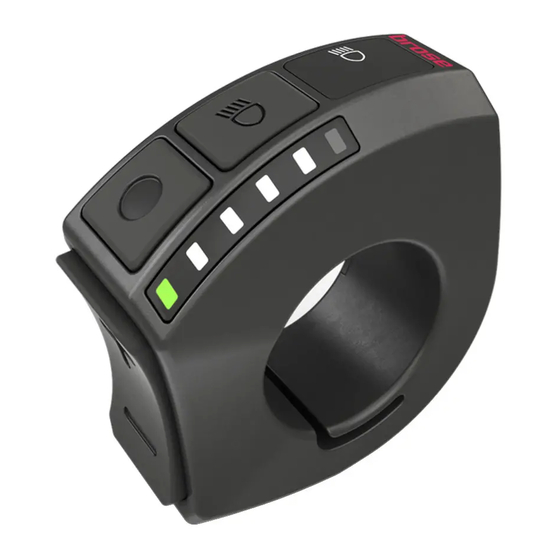
Page 21: Basics Of The Operating Elements (Buttons)
12 Basics of the operating elements (buttons) Button (On/Off) › Press the button to switch the Brose Drive System on or off. Button (Menu) In case of the operation of the control unit without the display unit, the ... -
Page 22: Basics Of The Displays
LED band (2) . In normal operation, the battery charge Fig. 3: Displays of the Display Remote control unit level is displayed in the LED band. Press the or button to display the (1) Lighting/Bluetooth display... - Page 23 Display Remote Display Central 23 | DE Before the first commissioning Display Central display unit 11:59 11:59 47.5 47.5 Trip Trip Standard Plain Design Fig. 4: User interface of Display Central display unit (1) System status information (4) Current support level (e.g.
-
Page 24: Menu Structure/Navigation Of Display Central Display Unit
DE | 24 Display Remote Display Central Before the first commissioning 14 Menu structure/navigation of Display Central display unit The menu structure of the display unit is To access the menu, stop or start the as follows: e-bike and proceed as follows with the e-bike stationary: ∙... -
Page 25: Operation And Handling
Display Central 25 | DE Operation and handling Operation and handling 15 Switching the Brose Drive System on and off Switching off INFORMATION ∙ Press the button on the control unit ∙ The Brose Drive System can only be for at least 1.5 seconds. -
Page 26: Selecting The Support Level
Display Remote Display Central Operation and handling 16 Selecting the support level Your Brose Drive System has four levels 16.1 Display Remote control unit of support. During the ride, the current charge status of the battery is displayed in the You can adjust how much the e-bike LED band. -
Page 27: Brose E-Bike App (Bluetooth ® Connection)
E-Bike App. Mobile terminal INFORMATION ∙ Delete the Bluetooth connection ® to the Brose Display Remote in the You can download the Brose E-Bike system settings. App at www.brose-ebike.com. There you will also find detailed information on requirements and functions. -
Page 28: Using The Push Assist
button for as long as you need the push assist function. INFORMATION › In Display Remote, all LEDs in the LED band light up. During the operation of the Display › WALK appears on the Display Central display unit, the displays on Central display. -
Page 29: Switching The Lighting On And Off
19 Switching the lighting on and off In the version where the cycling light is 19.1 Switching the lighting on / off powered by the Brose Drive System, the manually button on the control unit can be used ∙ Press the button on the control unit to switch the front and rear lights on and to switch on the lighting. -
Page 30: View
INFORMATION An error has occurred Individual functions may be deacti- (see chap. 27 on page 36) vated depending on the e-bike model. Detailed information is available from your e-bike manufacturer and your authorised Brose specialist dealer. -
Page 31: Battery Charge Level Indicator
INFORMATION When operating with the Brose Display < 20% Central display unit, the displays on the Brose Display Remote control unit are < 10% deactivated. The charge level of the battery can be INFORMATION... -
Page 32: Menu And Settings
INFORMATION To access the menu and the settings, the following requirements must be met: Please note that not every Brose Drive System has all setting options. It is ∙ The Display Central display unit is possible that some menu items are not mounted and connected;... -
Page 33: Settings
Mobile devices can be connected via (see chap. 25 on page 34) the Bluetooth interface to use the Brose ® Information E-bike app. ∙ Information about your Brose Drive ∙ (see chap. 17 on page 27) System (e.g. product name and software version). -
Page 34: System Settings
(1-20 minutes) of your Brose Drive System. Light Custom.Assistance ∙ Settings for the lighting (only if the lighting is powered by the Brose Drive ∙ Adjust the support levels individually System). to your needs. › The lighting is switched on and off Default Settings automatically. -
Page 35: Troubleshooting
Display Remote Display Central 35 | DE Troubleshooting Troubleshooting problems occur when using your Brose Drive System, first check listed points Chapter Troubleshooting In many cases, you can already remedy the situation yourself. If an error is indicated in the LED band of the control unit or in the display of the... -
Page 36: Error Displays
Menu and settings 27 Error displays The control unit and the display unit Depending on the type of fault, the show error messages of the entire Brose drive may be switched off automatically. Drive System. Continuing to cycle without support from the drive is possible at any time. - Page 37 Display Remote Display Central 37 | DE Menu and settings 27.1 Error indications on the Display Remote control unit Display of LED band Remedy Extreme temperatures cause an error. Disconnect the battery and charger from the power source and wait until the temperature of the battery and charger has normalised.
- Page 38 11:59 Check Speed Sensor Fig. 12: Example of error message Indication on the display Remedy Switch off the Brose Drive System. Check the speed sensor and the position of the Check Speed Sensor magnet. Restart the Brose Drive System. Switch off the Brose Drive System.
-
Page 39: Transport, Maintenance And Cleaning
For service or repairs to the Brose Drive moisture penetration. System or in the event of a component obtain appropriate protectors from failure (e.g. battery or charger), contact specialist dealers. -
Page 40: Cleaning
» Switch Brose Drive » Switch off the Brose Drive System. System and remove the battery » Unplug the charger from the socket. when cleaning the e-bike or the » Cover the power supply contacts. -
Page 41: Technical Data
Display Remote Display Central 41 | DE Technical data Technical data 31 Brose Display Remote E41227 control unit Brose Display Operating E 41227 2.400 - 2.480 MHz Remote frequency L × W × H 46 × 43 × 21 mm... -
Page 42: Brose Display Central E41229 Display Unit
DE | 42 Display Remote Display Central Technical data 32 Brose Display Central E41229 display unit Brose Display Operating E 41229 2.400 - 2.480 MHz Central frequency L × W × H 84 × 70 × 13 mm Electrical data 12 V max. -
Page 43: Disposal
Display Remote Display Central 43 | DE Disposal Disposal ONLY FOR EU COUNTRIES The batteries, chargers, control unit, display unit, drive unit, speed sensor and According to European accessories, as well as the packaging, Directive 2006/66/EC, must be recycled in an environmentally defective or used friendly manner. - Page 44 ∙ Always ensure proper disposal to ∙ RoHS Directive (2011/65/EU) counteract littering of public spaces. ∙ If applicable, use existing options Please return Brose e-bike components to reuse used batteries instead of that are no longer serviceable to an disposing of them, e.g. by repairing authorised Brose specialist dealer.
-
Page 45: Service
All rights reserved. The contents of this document have been prepared with the utmost care. However, Brose accepts no liability for the accuracy, completeness and up-to-dateness of the content. The contents are for information purposes only and do not... - Page 48 Brose Antriebstechnik GmbH und Co. Kommanditgesellschaft, Berlin Sickingenstr. 29-38 10553 Berlin Germany Phone: +49 30 343498 100 service.ebike@brose.com www.brose-ebike.com V 2.3 09/2022...
Need help?
Do you have a question about the Display Remote and is the answer not in the manual?
Questions and answers