Advertisement
Quick Links
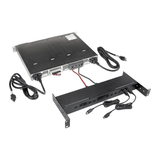
VNM 12 PS/PSR Power Supply • Installation Guide
The Extron
VNM 12 PS and VNM 12 PSR power supplies provide an efficient
®
method to connect power to as many as 12 VN-Matrix 200 or 300 Series
encoder/decoder units in 19 inch equipment racks. The single rack space (1U)
frame houses dual power supply modules (VNM 12 PS) or three hot-swappable
power supply modules (VNM 12 PSR). A 12-way power distribution panel,
VNM 12 PSD, attaches to the rear of the equipment rack. Cables are provided
for connection between the panel and encoder/decoder units.
The VNM 12 PS consists of two assemblies:
the PSU (power supply unit) and,
z
the PSD (power supply distribution) panel.
z
The distribution assembly (VNM 12 PSD) is a 1U, 19 inch rack mount unit that
provides an interface from the power supply unit to the VN-Matrix™ 200 or
VN-Matrix 300 series encoder/decoders.
Features
Compatible with VN-Matrix 200 or VN-Matrix 300 Series encoders and
z
decoders.
Simplified cabling — Two cables from power supply to distribution assembly.
z
Hot-swappable triple supplies (VNM 12 PSR only) — Provide redundant power for up to 12 encoder/decoder units and
z
enable quick replacement with zero downtime.
Rack Mounting
VNM 12 PS and VNM 12 PSR
With built-in brackets and supplied hardware, both
units mount in a standard 19 inch rack in a 1U
space. Go to
www.extron.com
guidelines and further rack mounting details.
VNM 12 PSD
This unit has adjustable rack ears. It may be mounted
directly behind the power supply if space is available.
Alternately, it can be mounted near the PSU and as
far to the rear of the rack as possible. Adjust the
mounting brackets to ensure the two main supply
cables can be connected to the power supply.
Distribution Assembly to
PSU Connection
Refer to the diagram at right to connect
the PSU to the PSD assembly.
1.
Remove the terminal cover
from the rear of the VNM 12 PS
or VNM 12 PSR unit.
2.
Connect the cables from the PSU D-sub
connector to the corresponding power
supply terminals.
3.
Plug the D-sub connector into the rear
panel as shown.
CAUTION:
The rear panel terminals are not color coded. Connect the black wires to the terminal
labeled RTN or GND. Connect the red wires to the side not labeled.
for UL rack mounting
Terminal Cover
a
c
PSU D-sub
Connector
VN-Matrix
Encoder/Decoders
VNM 12 PS
VNM 12 PSR (shown)
VNM 12 PS
or VNM 12 PSR
VNM 12 PSD
Power Supply
Terminals
-1
N
LA
-2
N
U S
LA
ST
AT
IE S
E R
0 S
IP
N
-1
R
LA
2 0
O VE
N
-2
R IX
LA
U S
A T
B /D
VI
AT
ST
-M
R G
V N
IE S
E R
0 S
IP
N
-1
2 0
R
LA
-2
O VE
N
R IX
VI
LA
U S
A T
B /D
AT
-1
R G
ST
N
-M
LA
-2
V N
N
U S
LA
AT
ST
IE S
E R
-1
0 S
IP
N
2 0
R
LA
-2
O VE
N
R IX
VI
LA
U S
A T
B /D
AT
-1
R G
ST
N
-M
LA
-2
V N
N
U S
LA
AT
ST
IE S
E R
0 S
IP
2 0
R
O VE
R IX
VI
A T
B /D
-1
R G
N
V N
-M
LA
-2
N
U S
LA
ST
AT
N
-1
LA
N
-2
LA
U S
AT
ST
Red
Connect postitive cables.
(Terminal is NOT color coded.)
b
Black
Connect GND / RTN cables.
(Terminal is NOT color coded.)
VNM 12 PS
VNM 12 PSR
Rear
IE S
E R
0 S
IP
2 0
R
O VE
R IX
VI
A T
B /D
R G
-M
V N
IE S
E R
0 S
IP
2 0
R
O VE
R IX
VI
A T
B /D
R G
V N
-M
IE S
E R
0 S
R
IP
2 0
O VE
R IX
VI
A T
B /D
R G
V N
-M
IE S
E R
0 S
R
IP
2 0
O VE
R IX
VI
A T
B /D
-M
R G
V N
1
Advertisement

Subscribe to Our Youtube Channel
Related Manuals for Extron electronics VNM 12 PS


Summary of Contents for Extron electronics VNM 12 PS
- Page 1 VNM 12 PS/PSR Power Supply • Installation Guide The Extron VNM 12 PS and VNM 12 PSR power supplies provide an efficient ® VN-Matrix method to connect power to as many as 12 VN-Matrix 200 or 300 Series Encoder/Decoders encoder/decoder units in 19 inch equipment racks. The single rack space (1U) frame houses dual power supply modules (VNM 12 PS) or three hot-swappable power supply modules (VNM 12 PSR).
- Page 2 If a power supply module fails, it may be replaced without removing power. NOTE: Failed power supply modules in the VNM 12 PS can also be replaced without removing AC power. However, if either module fails, depending upon how many VN-Matrix devices are connected, DC power output may be shut down.
Need help?
Do you have a question about the VNM 12 PS and is the answer not in the manual?
Questions and answers